
Related Manuals for Rigel 377


Summary of Contents for Rigel 377
- Page 1 Rigel 377 Electrosurgical Analyser Instruction Manual 367A550 Issue 1.0 November 2010 © 2010 Seaward Group Issue 1.0...
- Page 2 Limited Warranty & Limitation of Liability Rigel Medical, part of the SEAWARD GROUP guarantees this product for a period of 1 year. The period of warranty will be effective at the day of delivery. Calibration Statement The Rigel 377 Electrosurgical Analyser is fully calibrated and found to be within the specified performance and accuracy at the time of production.
- Page 3 Disposal of old product The Rigel 377 has been designed and manufactured with high quality materials and components, which can be recycled and reused. When this symbol is attached to a product it means the product is covered by the European Directive 2002/96/EC.
-
Page 4: Table Of Contents
3.2. HF Leakage ............. - 12 - 3.3. Power Test............... - 15 - ABOUT.............. - 17 - MAINTAINING THE RIGEL 377 ....... - 18 - 5.1. Cleaning the Analyser ..........- 18 - 5.2. User Maintenance ........... - 18 - 5.3. -
Page 5: Declaration Of Conformity
EN 50082-1 (1992) Electromagnetic Compatibility. Generic Immunity Standard: IEC1000-4-2, -4-3, -4-4, -4-5 The tests have been performed in a typical configuration. This Conformity is indicated by the symbol , i.e. “Conformité Européenne” Rigel 377 Instruction Manual – Version 1.0 - 5 -... -
Page 6: Before You Power Up
Before you power up Ensure the mains switch positioned at the base panel of the Rigel 377 is set to the appropriate voltage range i.e. 230VAC +/- 10% or 120 VAC +/- 10%. Ensure none of the ventilation holes are covered during operation including the ones on the base panel. -
Page 7: Introduction
The Rigel 377 Electrosurgical Analyser is a versatile bench-mounted yet portable tool, for testing the performance of electrosurgical equipment. Utilising a large, full colour graphical display, the Rigel 377 is the first fully stand-alone electrosurgical analyser that can offer true intuitive, user friendly operation and operator safety. -
Page 8: Key Features
Stylish and rugged enclosure – with small footprint ideal for in-situ testing Graphic colour user interface - for fast and easy navigation and connection to Future upgrade ready – download future upgrades from the web into your tester Rigel 377 Instruction Manual – Version 1.0 - 8 -... -
Page 9: Getting Started
2. Getting started The Rigel 377 has been designed to ensure that the user is able to test: quickly, easily and safely. The interfaces to the Rigel 377 have been segregated into a high-voltage area (side panel) and a safe low voltage area (front panel). This arrangement also ensures that test leads carrying high frequency power are kept as short as possible, and directly facing the equipment under test. -
Page 10: Rigel 377 Includes
3 x Jumper Links (p/n 43b759) • 2.3. Optional Accessories Finger switch adaptor • Foot switch adaptor cable set • Hard carry case • SMB to BNC Oscilloscope connection lead (p/n 367A950) • Rigel 377 Instruction Manual – Version 1.0 - 10 -... -
Page 11: Test Modes
The variable resistance (0 – 500 ) is connected to the two black connectors on the front panel. Select the REM test from the main menu shown below. Rigel 377 Instruction Manual – Version 1.0 - 11 -... -
Page 12: Hf Leakage
The HF Leakage test measures the HF leakage current in various test configurations (see appendix A), and compares the result to a user set pass/fail value. Select the HF LEAKAGE test from the main menu, shown below. Rigel 377 Instruction Manual – Version 1.0 - 12 -... - Page 13 Four different measurement scenarios have been described in the particular standard IEC 60601-2-2; See appendix A for all available leakage settings. Use the rotary encoder to change between the different leakage configurations. Use either the graph mode, shown below. Rigel 377 Instruction Manual – Version 1.0 - 13 -...
- Page 14 Press the rotary encoder to activate the SET LOAD and LEAKAGE LIMIT return to the GRAPH mode by using the SHOW DIAGRAM fast key. The Rigel 377 could display the following details after the test. Press the HOLD key to freeze the reading on the screen.
-
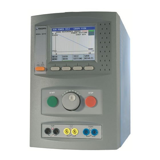
Page 15: Power Test
(Continuous Single Test) or at a range of loads (Power Distribution Graph). The load will vary from a start value to an end value with a number of intervals (resolution). The Rigel 377 will control the EUT by using the internal footswitch controller. - Page 16 Rigel 377 will display continuously 377 will display the power distribution updated readings. graph. At the end of the test, toggle between GRAPH MODE and DATA by pressing the GOTO DATA fast key. Rigel 377 Instruction Manual – Version 1.0 - 16 -...
-
Page 17: About
4. About This screen provides details on the Rigel 377’s firmware version Ensure you have this information available when contacting Rigel Medical for Technical Support or Service. See section 5.3 for more information on Service and Calibration. Rigel 377 Instruction Manual – Version 1.0... -
Page 18: Maintaining The Rigel 377
Do not allow liquid inside the Rigel 377 or near the sockets. Do not use: abrasives, solvents, or alcohol. If any liquid is spilt into the Rigel 377 case, the analyser should be returned for repair, stating the cause of the defect. -
Page 19: Return Instructions
By obtaining a Returns Number, your service request can be booked in advance thus reducing the down time of your equipment. When asking for a Returns Number, please quote: Instruments name and model • Serial number • Firmware version • Rigel 377 Instruction Manual – Version 1.0 - 19 -... -
Page 20: Specifications
Remote foot switch control (CUT) 2 x 4 mm - yellow, Single relay contact Remote foot switch control (COAG) 2 x 4 mm - blue, Single relay contact USB port PC interface Rigel 377 Instruction Manual – Version 1.0 - 20 -... -
Page 21: General Specification
Operating Temperature 15 ˚C to 35 ˚C Storage Temperature 0˚C to 50 ˚C Mains power 115/230 ±10% VAC; 48 to 66 Hz, 35 VA Fuses 2 x 1.6 A (T) ceramic Rigel 377 Instruction Manual – Version 1.0 - 21 -... -
Page 22: Appendix Aiec 60601-2-2 Leakage Tests
TEST CODE 1212 IEC 601-2-2 part 1 FIGURE 103 MEASUREMENT OF H.F. LEAKAGE CURRENT WITH NEUTRAL ELECTRODE ISOLATED FROM EARTH AT HIGH FREQUENCY EARTH ISOLATED ESU MONO-POLAR ELECTRODE CUT MODE NEUTRAL ELECTRODE Rigel 377 Instruction Manual – Version 1.0 - 22 -... - Page 23 COAG MODE FIRST ELECTRODE TEST CODE 2122 IEC 601-2-2 part 1, FIGURE 104 MEASUREMENT OF H.F. LEAKAGE CURRENT FROM A BIPOLAR ELECTRODE EARTH REFERENCED ESU BIPOLAR ELECTRODE COAG MODE SECOND ELECTRODE Rigel 377 Instruction Manual – Version 1.0 - 23 -...
- Page 24 IEC 601-2-2 part 1 FIGURE 101 MEASUREMENT OF H.F. LEAKAGE CURRENT WITH NEUTRAL ELECTRODE REFERENCED TO EARTH AND LOAD BETWEEN ELECTRODES EARTH REFERENCED ESU MONO-POLAR ELECTRODE COAG MODE NEUTRAL ELECTRODE Rigel 377 Instruction Manual – Version 1.0 - 24 -...
-
Page 25: Appendix Biec 60601-2-2 Power Tests
ACTIVE AND NEUTRAL ELECTRODE TEST CODE 0220 IEC 601-2-2 part 1 FIGURE 105 MEASUREMENT OF OUTPUT POWER MONO-POLAR OUTPUT USER SET LOAD RESISTANCE MONO-POLAR ELECTRODE COAG MODE ACTIVE AND NEUTRAL ELECTRODE Rigel 377 Instruction Manual – Version 1.0 - 25 -...
Need help?
Do you have a question about the 377 and is the answer not in the manual?
Questions and answers