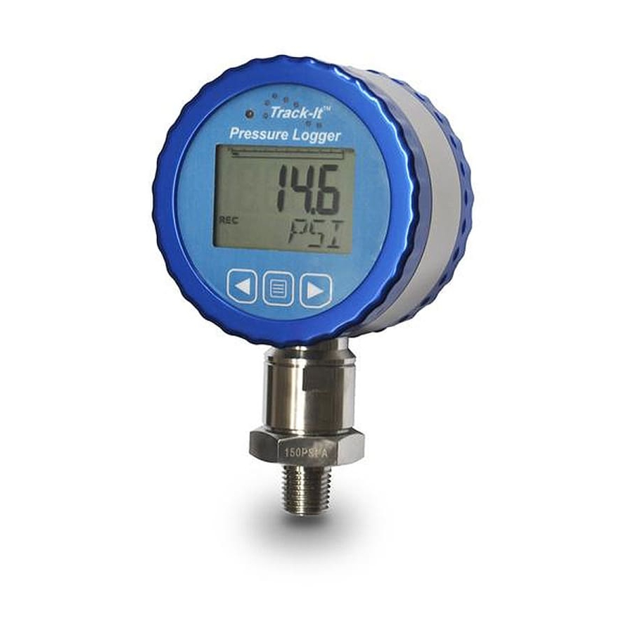
MONARCH INSTRUMENT Track-It Instruction Manual
Pressure transmitter with digital display
Hide thumbs
Also See for Track-It:
- Instruction manual (27 pages) ,
- User manual (2 pages) ,
- Quick start manual (2 pages)
Table of Contents

Related Manuals for MONARCH INSTRUMENT Track-It


Summary of Contents for MONARCH INSTRUMENT Track-It
- Page 1 Instruction Manual Track-It Pressure Transmitter ™ with Digital Display 15 Columbia Drive Amherst, NH 03031 USA Phone: (603) 883-3390 • Fax: (603) 886-3300 E-mail: support@monarchinstrument.com Website: www.monarchinstrument.com...
- Page 2 Warranty Registration and Extended Warranty Coverage information is available online at www.monarchinstrument.com. Track-It is a trademark of Monarch Instrument. Android and Google Play are trademarks of Google Inc. The Android robot is reproduced or modified from work created and shared by Google and used according to terms described in the Creative Commons 3.0 Attribution License.
-
Page 3: Table Of Contents
TABLE OF CONTENTS INTRODUCTION .............. 1 GETTING STARTED ............2 2.1 Install USB Driver and Track-It Software .... 2 2.2 Connect Transmitter and Start Track-It Software ..3 2.3 Configure Transmitter ..........3 3.0 INSTALLATION .............. 4 3.1 Vent ................ 4 4.0 POWER / TRANSMITTER CONNECTIONS ...... 5 5.0 BUTTONS AND MENU ............. 7 5.1 Menu Modes ............ 7 5.2 Menu Options ............ 8 LCD ................10 7.0 LED ................ 12 8.0 TRACK-IT PC SOFTWARE ..........12 8.1 Preferences ............ 13 8.2 Input Setup ............ 14... -
Page 4: Introduction
Power and mA out connection is via a 4 pin DIN 43650 IP65 connector on the rear panel. The unit is easily configured using the free downloadable Track-It™ PC Software. There is a mini USB connector on the rear of the unit allowing connection to a PC for programming and data download. Data download can also be done with an Android™... -
Page 5: Getting Started
Logger and software manuals may also be accessed from the installation screen. 2.2 Connect Transmitter and Start Track-It Software Plug the Track-It Pressure Transmitter into an available USB port on the PC using the supplied cable. If the Found New Hardware Wizard appears, follow the prompts to complete the installation. -
Page 6: Configure Transmitter
If the USB driver is installed properly, you will see Device Connected displayed in the lower right-hand corner of the Track-It Software window. 2.3 Configure Transmitter Select the Device Setup tab as shown below. The software will automatically retrieve and display the transmitter configuration. -
Page 7: Installation
3.0 INSTALLATION The Pressure Transmitter can be ordered with various pressure sensor ranges to cover most applications. Sensors have a ¼" NPT or ½"-NPT thread, dependent on pressure range, that is intended to screw into the pressure source. Make sure to use suitable tape or thread sealant/dope on the threads before inserting the Transmitter into the port. -
Page 8: Power / Transmitter Connections
4.0 POWER / TRANSMITTER CONNECTIONS The transmitter has a 4-pole DIN43650 connector on the rear panel for power and current out connections. A mating plug (Hirschmann GDS 307) and flat gasket (Hirschmann GDS 307-4) are supplied. The plug is a Form C connector with 3 Poles + Ground, 9.4 mm pin spacing, with a black fiberglass reinforced polyamide housing, and a PG 7 cable entry which accommodates a 4.5 mm to 6 mm (0.177 to... - Page 9 To connect, remove the screw and plug base from the housing. Thread the cable through the PG7 gland (A), metal washer (B) and rubber washer (C). Insert the wires into the plug housing (D) and strip the wire ends ~0.24" (6mm). The plug has four compression screw connections.
-
Page 10: Buttons And Menu
The display will automatically exit back to the real-time display if there is no activity for 10 seconds. The content of each menu is set up in the Track-It PC Software. In addition, the admin menu can be locked; in this situation, the user at the Transmitter cannot enter this menu and will receive a LOCK message. -
Page 11: Menu Options
The list on the next page is in alphabetical order. Please note that the actual order in which these items appear is dependent on settings set in the Track-It PC Software. Backlight BKLT – AUtO/OFF –– In Auto mode, the backlight will come on whenever a button is pressed. - Page 12 – ON/OFF – Will toggle the record mode of Record On/Off the unit (Only visible if record mode set to “Button Press” in the Track-It PC Software). Press ► button to toggle on/off status. ZERO – OFF/EnAb – Will enable the zero offset Zero Mode feature.
-
Page 13: Lcd
- 07.24, time in 12 or 24-hour format (12-hour format will be indicated by AM or PM – 08:30 AM), and memory usage as a % of available memory. Values shown are set in the display setup using the Track-It PC Software. See 8.4 Display Setup... - Page 14 There are various icon indications on the display that indicate the following: Indicates the unit is currently recording. This icon will blink at a 2 second rate. Indicates the unit is currently triggered and waiting to record. Record is initiated by time delay or button depending on configuration. Indicates an Alarm condition;...
-
Page 15: Led
PC Software. Please refer to Section “2.0 GETTING STARTED”. The free Track-It Software runs on a PC and gives the user complete control in programming the Transmitter and allows for the upload, examination and archiving of data recorded on the Transmitter and setting the current output. -
Page 16: Preferences
8.1 Preferences Select Preferences then the Eng Units tab. You will see the pop-up box shown below. These Engineering Units apply to the data read from the Transmitter and displayed on the graph or in the data table. If the Units from Logger box is checked - the selection of engineering units here is ignored and the engineering units used will be as set by default in the Transmitter. -
Page 17: Output Setup
The units selected here will be used when reading data from the Transmitter unless overridden in the Preferences menu. The Pressure channel cannot be disabled – the Transmitter will always record Pressure. Note that selecting anything other than Instantaneous for Sample Mode (the Transmitter only takes a reading at the Record Rate) will cause the Transmitter to take readings at the highest sample rate. -
Page 18: Display Setup
If Default is checked the output will be 4mA at 0 pressure and 20mA at the full scale pressure of the device. The scaling cannot be changed in default mode. The pressure is set and shown in the units selected under the Input tab. -
Page 19: Menu Setup
Decimal Places will define how the data is displayed. Auto will always use the maximum number of digits available. LCD Time Out determines how long the LCD will be on before blanking. The Time and Date formats can be selected as shown. The Display Average checkbox enables the real-time update to be a rolling average of the last four readings. -
Page 20: Track-It Transport App
9.0 TRACK-IT TRANSPORT APP Track-It Transport is a free Application for Android that allows you to use your mobile device to start and stop recording and transfer data using a USB On-the-Go cable. https://play.google.com/store/apps/details?id=com.trackit.transporter 10.0 SPECIFICATIONS 10.1 Measurement Various pressure ranges absolute and gauge... -
Page 21: General
0-100% indication, backlit Alarms 2 user-programmable alarms (High or Low) Communication Mini USB connection Track-It Software—Program device, view data (historic or Software real-time), export to spreadsheet. Enclosure Anodized Aluminum and 316L Stainless Steel 2.94" (74.6mm) diameter x 1.82" (46.3mm) deep x 4.78"... -
Page 22: Isolated Current Output
10.3 Isolated Current Output 4 to 20mA (Min. 3.6mA, Max. 21.5mA) Range User scalable for pressure Isolation 500V to 24VDC power Compliance Voltage 12VDC @24Vdc supply (Min 11V @21.6VDC supply) Accuracy ±0.06% Resolution 6µA Update Rate 125 msec typical 10.4 Operating Environment Temperature -4 °F to 185 °F / -20°C to +85°C Humidity 0-100% Environmental... -
Page 23: Compliance
Replacement O-ring Seal, 2-pack PN: 5396-9916 for units with S/N <4103275 USB 2.0 to 2.0 mini 3 ft. cable PN: 5396-9911 Replacement DIN46350 Mating Plug PN: 5396-9917 and Gasket Track-It Calibration Software PN: 5396-9915 For additional accessories and details, see webpage. - Page 24 The Professional’s Choice Monarch Instrument is committed to excellence and quality in manufacturing, sales, and service. Track-It ™ Data Loggers Panel Tachometers Portable Tachometers Frequency Portable Strobes Fixed Mounted Converters Strobes Speed Sensors DataChart ™ Paperless Recorders 15 Columbia Drive, Amherst NH 03031 USA Tel.: (603) 883-3390 // Fax: (603) 883-3390...
Need help?
Do you have a question about the Track-It and is the answer not in the manual?
Questions and answers