Advertisement
Quick Links
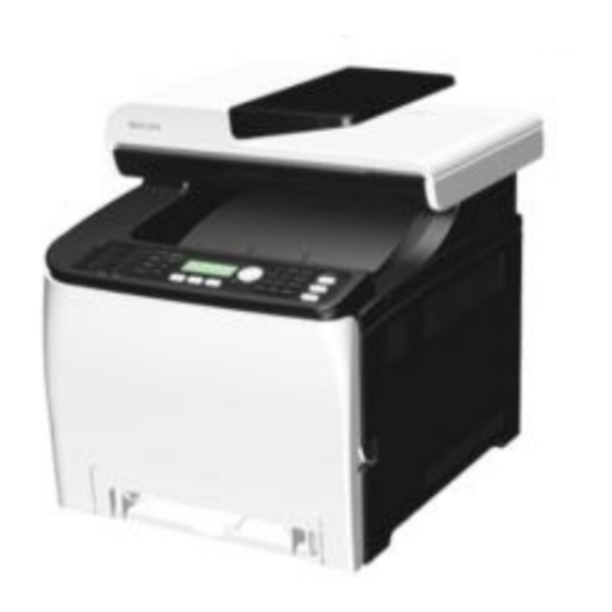
This training course provides service technician training for the PE-MF4/PE-
P4 series.
The differences between this series and the previous PE-MF3/PE-P2 series
are also explained.
Revision History
- Version1.2
(Revised 9
Slide 12:
Updated Monthly Average Print Volume
MF4a:0.7K prints
MF4c:0.8K prints
P4a:0.4K prints
P4c:0.5K prints
- Version1.1
(Revised 17
Slide 10: Long (High Yield) AIO will be available for NA, EU, AP, CN models.
th
Apr.
2014)
th
Feb.
2014)
1
Advertisement

Related Manuals for Ricoh PE-MF4 Series


Summary of Contents for Ricoh PE-MF4 Series
- Page 1 This training course provides service technician training for the PE-MF4/PE- P4 series. The differences between this series and the previous PE-MF3/PE-P2 series are also explained. Revision History - Version1.2 (Revised 9 Apr. 2014) Slide 12: Updated Monthly Average Print Volume MF4a:0.7K prints MF4c:0.8K prints P4a:0.4K prints...
- Page 2 This section provides an overview of the machine, and the options that can be installed.
- Page 3 Pe-MF3a was 16 ppm. Pe-MF3a/P2a were GDI models. Memory specs are changed from PE-MF3/P2. Built-in Wireless LAN is a new feature. It was not available in previous models.
- Page 4 No additional notes...
- Page 5 Duplex can be used for printing and copying. In some earlier models in this series, duplex could not be used for copying.
- Page 6 No additional notes...
- Page 7 No additional notes...
- Page 8 No additional notes...
- Page 9 No additional notes...
- Page 10 Based on ISO 19798 Revised 17 Feb. 2014 - Long (High Yield) AIO will be available for NA, EU, AP,CN models.
- Page 11 The waste toner tank is the same as the one that is used for previous models in this series. Waste toner tank yield measurement based on 5%, 3P/J, 50% color ratio Color ratio: 50% means that half the jobs are black-and white, and half are color Compatible with Pe-P1, Pe-MF1, Pe-MF2, Pe-P2, and Pe-MF3...
- Page 12 Same as the PE-MF3/P2 series. Revised 9 Apr. 2014 -Updated version MF4a:0.7K prints MF4c:0.8K prints P4a:0.4K prints P4c:0.5K prints -Previous version Monthly Average Print Volume MF4a, P4a: 0.65K prints MF4c: 1.1K prints P4c: 0.8K prints...
- Page 13 This section provides an overview of the main specifications and explains improvements over the previous models in the PE series.
- Page 14 No additional notes...
- Page 15 Same as PE-MF3, except where mentioned. Why is 1st copy time so much slower than the 1st print time? Scanner initialization and movement to the start position takes more time. Duplex printing cannot be done for thick paper (more than 90 g/m Printing on OHP transparencies is not possible.
- Page 16 PDL for PE-MF3a: DDST (GDI)
- Page 17 These specs are the same as PE-P2, except where mentioned.
- Page 18 PDL for PE-P2a: DDST (GDI)
- Page 19 No additional notes...
- Page 20 No additional notes...
- Page 21 If the machine power is kept on, the fusing unit will idle every 24 hours to prevent damage to the hot roller. But if the machine is turned off with pressure still applied, the hot roller could deform.
- Page 22 No additional notes...
- Page 23 No additional notes...
- Page 24 No additional notes...
- Page 25 Service Manual – 5. System Maintenance Reference – Firmware Updating...
- Page 26 No additional notes...
- Page 27 No additional notes...
- Page 28 No additional notes...
- Page 29 Service Manual – Preventive Maintenance...
- Page 30 PE-MF4c/P4c has an expected life of 180k.
- Page 31 The expected yield of these parts is 90k.
- Page 32 No additional notes...
- Page 33 Service Manual, Appendix 5: Machine Swap...
- Page 34 No additional notes...
- Page 35 No additional notes...
- Page 36 Operating Instructions – 1. Getting Started - Guide to Components 1. Top Cover: Open this cover to replace the print cartridge. 2. Control Panel: Contains keys for machine control and indicators that show the machine status. 3. Power Switch: Use this switch to turn the power on and off. 4.
- Page 37 Operating Instructions – 1. Getting Started - Guide to Components 1. Front Cover Open Lever: To open the front cover, pull this lever on the right side of the machine. 2. Cable Cover: Remove this cover when connecting cables to the machine. 3.
- Page 38 Operating Instructions – 1. Getting Started - Guide to Components 1. ADF (Auto document feeder) Cover 2. Output Tray for the ADF: Scanned sheets are fed here. 3. USB Flash Disk Port: Insert a USB flash disk for using the Scan to USB function or connect a digital camera using a USB cable for PictBridge printing.
- Page 39 Operating Instructions – 1. Getting Started - Guide to Components 1. Stop Fences: Pull up this fence to prevent paper falling off when printing a large amount of paper at a time. The fence can be adjusted at the A4/Letter or Legal size position.
- Page 40 No additional notes...
- Page 41 No additional notes...
- Page 42 1. Print Cartridges: Install the print cartridges from the machine rear, in the order of cyan (C), magenta (M), yellow (Y), and black (K). Messages appear on the screen when print cartridges need to be replaced, or new ones need to be prepared.
- Page 43 Operating Instructions – 1. Getting Started See the operation manual for details.
- Page 44 Operating Instructions – 1. Getting Started See the operation manual for details. Note the following. 1. [Stop/Start] key: Press this key to stop receiving incoming data from the computer. 2. [Job Reset] key: Press this key to cancel a job that is currently being printed or received.
- Page 45 1. Laser Optics Housing Unit 2. Print Cartridge (AIO) – AIO means ‘All-in-one’ 3. Development Roller (AIO) 4. Paper Exit 5. Fusing Unit 6. Fusing Lamp 7. Duplex Path 8. Transfer Roller 9. Registration Roller 10. By-pass 11. Paper Feed Roller 12.
- Page 46 No additional notes...
- Page 47 1. Paper path from tray 1 2. Duplex path 3. By-pass tray 4. Paper path from tray 2 (optional)
- Page 48 1.Color AIO Motor 2.Black AIO Motor 3.Duplex Motor 4.Transport/Fusing Motor 5.Registration Clutch 6.Paper Feed Clutch 7.Agitator Motor 8.ITB (Image Transfer Belt) Contact Motor...
- Page 49 1.Color AIO Motor 2.Black AIO Motor 3.Duplex Motor 4.Transport/Fusing Motor 5.Registration Clutch 6.Paper Feed Clutch 7.Agitator Motor 8.ITB (Image Transfer Belt) Contact Motor...
- Page 50 This machine uses four AIOs and four laser beams for color printing. Each AIO contains a drum, charge roller, cleaning brush, blade, development roller and mixing auger.
- Page 51 The charge that is applied to the image transfer roller pulls the toner from the drum to the transfer belt. Four toner images are put on the paper at the same time.
- Page 52 Toner transfers from the image transfer belt to the paper when the paper is fed between the image transfer belt and transfer roller. After transfer, the paper separates from the image transfer belt, because of a discharge plate immediately after the transfer roller.
- Page 53 The TM sensor board contains three TM sensors (one at the left, one at the center, and one at the right). The center TM sensor detects the density of the sensor patterns on the transfer belt. The TM sensor output is used for process control and for automatic line-position adjustment, skew, and color registration adjustments for the latent image.
- Page 54 Process control uses these components: Central TM (Toner Mark) sensors Temperature/humidity sensor at the rear right of the machine. This is used to determine whether the conditions have changed significantly enough so that process control must be done. Process control flow 1.
- Page 55 right of the ITB. This process takes about 22 seconds to be completed.
- Page 56 There are three execution modes: a) Development Bias Control and MUSIC (approx. 55 seconds), b) MUSIC only (approx. 22 seconds), c) No Execution The one that is used depends on conditions as described below. 1. Initial Toner amount control and MUSIC start automatically immediately after the power is turned on, if one of the following conditions occurs.
- Page 57 7.Job end: Toner amount control and MUSIC start automatically after a job when the machine gets a request to execute the toner amount control and MUSIC. MUSIC starts automatically after a job when the machine gets a request to execute MUSIC.
- Page 58 MUSIC (Mirror Unit for Skew and Interval Correction). MUSIC is also called Automatic Line Position Adjustment.
- Page 59 The EGB boards for the P4 and MF4 are identical. The controllers for the P4 and MF4 are not identical, but use many common parts.
- Page 60 Service Manual – Replacement and Adjustment – Electrical Components – EGB (Engine Board)
- Page 61 Serial Number: You must ask your supervisor how to input this number. LSU Adjustment: Input the values from the sheet that comes with the laser optics housing unit. What does Transfer Belt Adjust do? The new transfer belt may not be exactly the same length as the old one. With this SP mode, the machine calibrates the motor speed for the new belt (the speed is checked with a TM sensor pattern).
- Page 62 Service Manual – Appendix 3. Troubleshooting Guide – Service Call Conditions There is no SOM (Smart Organizing Monitor) in this series.
- Page 63 Service Manual – Troubleshooting – Image Problems...
- Page 64 These mechanisms are the same as in the RM-MF1 series. The previous models in this series used a CCD scanner.
- Page 65 No additional notes...
- Page 66 No additional notes...
- Page 67 No additional notes...
- Page 68 No additional notes...
- Page 69 This is the same as the PE-MF3/P2.
- Page 70 This machine uses two LDB units and one polygon mirror motor to produce latent images on four OPC drums (one drum for each color toner). There are two hexagonal mirrors. The polygon mirror motor rotates the mirrors clockwise and each mirror reflects beams from LD unit. The laser beam from the LD unit - C/M is directed to the Fθ...
- Page 71 No additional notes...
- Page 72 No additional notes...
- Page 73 MUSIC is done at the times explained in the process control section of the course.
- Page 74 No additional notes...
- Page 75 No additional notes...
- Page 76 No additional notes...
- Page 77 No additional notes...
- Page 78 No additional notes...
- Page 79 Steps 3 to 7 are a repeat of slide 1 of this procedure, except that we use the numbers from the excel file, and not from the printed sheet that comes with the unit.
- Page 80 No additional notes...
- Page 81 The mechanism is the same as the PE-MF3/P2.
- Page 82 The term AIO means ‘All-in-One’. All image creation components are in one easily- replaceable unit. Each AIO consists of the waste toner tank, print cartridge, development unit, and PCU. This gives the user easy replacement procedures and helps to make the engine module more compact.
- Page 83 Difference from previous model: There is only one cleaning blade for the charge roller in this new model.
- Page 84 The color AIO motor drives the central gear, as shown in the diagram below.
- Page 85 The high voltage supply board, which is at the left side of the machine, applies a dc and ac voltage (at a constant current) to the roller. The ac voltage helps to make sure that the charge given to the drum is as constant as possible. The machine automatically controls the charge roller voltage when process control is done.
- Page 86 Difference from previous model: There is only one cleaning blade for the charge roller in this new model. We will see the toner transport belt on the next slide.
- Page 87 See the next slide for more about the waste toner tank. There is another toner collection mechanism for the image transfer unit, and a separate collection bottle. This is explained in another section.
- Page 88 No additional notes.
- Page 89 This mixing mechanism prevents toner hardening and uneven image density in the outputs.
- Page 90 This machine uses mono-component toner, with no carrier, so a TD sensor is not necessary.
- Page 91 This system is used instead of a quenching lamp.
- Page 92 These two figures are stored in the memory chip in the AIO. Toner near-end: If you change from the default 200 sheets, the near-end detection point is moved earlier (in the case of 300 sheets) or later (in the case of 100 sheets) How to change the 200-sheet limit to 100 or 300? User tools >...
- Page 93 No additional notes...
- Page 94 This is the same as the PE-MF3/P2.
- Page 95 The paper end sensor detects whether paper is installed in the tray and whether the tray is set in the machine. This machine does not have a tray set sensor. This machine also does not have automatic paper size detection. The machine determines the paper size from the on-off timing of the registration sensor.
- Page 96 The clutches are shown in blue.
- Page 97 No additional notes...
- Page 98 No additional notes...
- Page 99 A projection at the right side of the tray set location releases the lock lever when the tray is installed in the machine.
- Page 100 No additional notes...
- Page 101 No additional notes...
- Page 102 No additional notes...
- Page 103 This is the same as the PE-MF3/P2.
- Page 104 No additional notes...
- Page 105 No additional notes...
- Page 106 No additional notes...
- Page 107 Because of this mechanism, the life of the transfer belt is longer (it is not necessary for the transfer belt to touch the color PCUs when the machine makes a black and white print). However, if the customer selects "Off" with the "ACS" setting, the four OPC drums always touch the image transfer belt.
- Page 108 No additional notes...
- Page 109 We will see more about the waste toner collection mechanism for the ITB later in this section.
- Page 110 In some places, you will see the term ‘2 Transfer’. This refers to what the paper transfer roller does (transfer from belt to paper).
- Page 111 The right end of the transfer unit is attached to the terminal from the high voltage power supply when you close the front cover.
- Page 112 No additional notes...
- Page 113 If the bottle is not set or if it is full, an error message appears on the LCD. Waste toner overflow and bottle set sensors: These are for the waste toner bottle that collects toner from the transfer belt. The waste toner from the drums is collected inside each AIO.
- Page 114 Normally, the life of the transfer belt unit is the same as the life of the machine. It should only be necessary to replace this unit if it becomes defective. What is the Transfer Belt Unit Life Counter (Reset Transfer Unit)? The resistance of the belt changes during its life.
- Page 115 Transfer Roller Unit: Contains the paper transfer roller...
- Page 116 No additional notes...
- Page 117 No additional notes...
- Page 118 This is the same as the PE-MF3/P2.
- Page 119 Springs always apply the correct pressure to the nip between the pressure roller and hot roller. When releasing the pressure release levers, the pressure roller moves away from the hot roller. If a paper jam occurs in the fusing unit, releasing these levers make it easy to remove jammed paper.
- Page 120 No additional notes...
- Page 121 Normally this lever should be up. A larger gap is needed for envelopes, which are thicker than paper. Lower the lever to increase the size of the gap between the hot roller and pressure roller. This prevents jams and wrinkling when printing on envelopes. Raise the lever to reduce the gap for all other print jobs.
- Page 122 No additional notes...
- Page 123 No additional notes...
- Page 124 No additional notes...
- Page 125 No additional notes...
- Page 126 No additional notes...
- Page 127 No additional notes...
- Page 128 Lab tests: Fusing idling mode 2 should be enough in most cases Menu – Machine Settings – High Humidity Mode...
- Page 129 No additional notes...
- Page 130 No additional notes...
- Page 131 No additional notes...
- Page 132 No additional notes...
- Page 133 No additional notes...
- Page 134 This is the same as the PE-MF3/P2.
- Page 135 1. Side Fence 2. Paper End Sensor 3. Paper Feed Roller 4. Relay Sensor 5. Relay Roller 6. Friction Pad 7. Paper Height Lever 8. Bottom Plate 9. Rear Fence...
- Page 136 No additional notes...
- Page 137 The next slide shows what happens after you put the tray in the machine.
- Page 138 No additional notes...
- Page 139 No additional notes...
- Page 140 G849 Service Manual – Replacement and Adjustment – Paper Feed Unit – Friction...
- Page 141 The End...
Need help?
Do you have a question about the PE-MF4 Series and is the answer not in the manual?
Questions and answers