Table of Contents
Advertisement
Advertisement
Table of Contents

Related Manuals for Itho Daalderop HRU ECO 350


Summary of Contents for Itho Daalderop HRU ECO 350
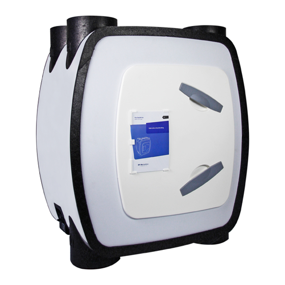
- Page 1 Itho Daalderop HRU ECO 350 Installation manual...
- Page 2 Original document.
- Page 3 Although this manual has been compiled with the utmost care, no rights can be derived from it. Itho Daalderop reserves the right to change products and manuals without prior notice. Due to our continuous process of improving our products, this document may differ from the product delivered to you.
-
Page 4: Table Of Contents
Content Safety and regulations 1.1. Security 1.2. Standards and guidelines Product information 2.1. Versions 2.2. Accessories 2.3. Technical data 2.4. Capacity chart 2.5. Capacity 2.6. Dimension drawings 2.7. Spare parts 2.8. Schemes Installation 3.1. Installation requirements 3.2. Installing the ventilation unit 3.3. -
Page 5: Safety And Regulations
Prevent children from playing with the ● In the event of defects, switch off the product and/or system. product and contact your installer or the Itho Daalderop service department ● Do not use the product in the presence immediately. of flammable or volatile substances such as alcohol, insecticides, petrol, etc. -
Page 6: Standards And Guidelines
Wants to carry out maintenance on the appliance. The government advises closing windows and doors in the event of a calamity. ● Take care not to damage the electrical circuit. ● Do not use the appliance to vacuum water boilers, heating systems, etc. ●... -
Page 7: Product Information
2. Product information 2.2. Accessories The HRU ECO 350 consists of a central balance ventilation unit with heat recovery, a mounting set and a condensate drain Article no. Type Description connection. 536-0124 RFT W Wireless control switch with Three modes and timer function... -
Page 8: Technical Data
2.3. Technical data HRU ECO 350 Description Symbol Unit LR / HR LP / HP DIMENSIONS AND WEIGHT Dimensions (HxWxD) — 848 x 730 x 479 Weight — CONNECTIONS Channel connections top side — 4x Ø 150 internal/Ø 180 external 2x Ø... -
Page 9: Capacity Chart
2.4. Capacity chart 500 Pa Power lines140 100 Pa 2.5. Capacity Line Pressu Power P Sound power Sound power level Capacity Q graph re dP radiated (LwA) Dissipation (LwA) m3/h] [Pa] Position 1 Minimum Position 1 Standard Position 1 Maximum Position 2 Minimum Position 2 Maximum Position 3 Minimum... -
Page 10: Dimension Drawings
2.6. Dimension drawings --+--- 480 - ithodaalderup... -
Page 11: Spare Parts
2.7. Spare parts 11 6 Legend Ventilation unit Bayonet rear side Heat exchanger Front panel Front door Filter Engine module Connection cap with control board and power cable Mosquito filter Frost valve Bypass valve... -
Page 12: Schemes
2.8.3. Vorstregeling The purpose of the frost control is to prevent the heat exchanger The HRU ECO 350 has as standard a 3-position control where the from freezing and to prevent ventilation. ventilation flow in the low position and the high position can be infinitely adjusted by means of potentiometers on the unit. - Page 13 2.8.4.1. Filter warning The control of the ventilation unit keeps track of when the filters The HRU ECO 350 has two filters, one for each air flow. Both need to be cleaned or replaced by means of a counter. If a dirty filters are placed in the ventilation unit in such a way that they filter is detected, the LED (4) on the ventilation unit flashes orange.
- Page 14 With the coupling type VKK and VKK-HB it is possible to If the ventilation unit detects that the filter needs to be cleaned or connect the HRU ECO 350 to the Remeha HR combi boiler the replaced, the unit sends a message to the controllable CO2 sensor Avanta.
-
Page 15: Installation
Always ensure that the ventilation unit is mounted in such a way that the ducts are connected to the correct inlet and outlet openings! To prevent noise complaints, Itho Daalderop recommends connecting the two ducts coming from the house with silencers. The ventilation unit is mounted on the wall. - Page 16 Mounting positions High rise 'standard High-rise 'twisted' (1) Low-rise 'standard Low-rise 'twisted' (1) 1) See Conversion for assembly. Legend Exhaust air to the outside Supply air from outside Exhaust air from home Supply air to dwelling Close...
- Page 17 Also turn the bayonet at the back one quarter turn counterclockwise and remove the bayonet. The HRU ECO 350 comes standard with the motor module on the left side. If it is more convenient for the duct system, the ventilation unit can be 'mirrored' easily and without tools before being mounted on the wall.
- Page 18 e) Place the front door on the new front as shown. Turn the front door a quarter turn clockwise until it is neatly vertical. (g) Fit both filter holders. Make sure that the round disc of foam, in the hole against the changer between the door and the changer, is present.
- Page 19 3.2.4. Wall mounting b) Fix the wall plate level on the wall using 5 screws (mounting material not supplied). a) Determine the exact location of the unit, taking into account the Installation requirements on page 15. c) Hang the ventilation unit with the mounting strip on the wall Standard assembly.
-
Page 20: Connecting Condensation Drain
3.3. Connecting condensation drain ä Attention If the ventilation unit is placed outside the thermal shell of the dwelling (for example in an uninsulated attic), the condensation drain must be thermally insulated up to the ventilation unit. In winter, the exhaust air from the house can condense in the heat exchanger. -
Page 21: Connecting The Channels
3.4. Connecting the channels 3.4.3. Supply air to dwelling ä Warning! When using the unit in the stacked construction, return flow to the house from the central exhaust air duct must be prevented at all times. In this case, a mechanical non-return damper must be used in the discharge duct of the unit. -
Page 22: Dipswitch Settings
Both the ventilation unit and the boiler need a supply and an exhaust duct to and from the outside. The purpose of the coupler is to simplify the ducting system of the HRU ECO 350 and the boiler. 3 2 1 ä... -
Page 23: Operation
A combination of the above possibilities. The current ventilation position can always be read on the You can register up to 20 wireless control switches and/or (optional) external or RH sensor. sensors on an Itho Daalderop ventilation unit or system. CO2 sensor... -
Page 24: Sensors
4.3. Sensors 4.4.3. Sign up wireless sensors Connect the remote sensor to the ventilation unit in the following way: The ventilation unit can be controlled by the following available sensors: a) Disconnect the power supply to the ventilation unit by removing the plug from the wall socket. -
Page 25: Commissioning
5. Commissioning 5.1. Preparation Note Prior to commissioning If a VKK coupler or a heat pump is fitted, you will need to ● adjust the dipswitch settings. See Dipswitch settings on page The ventilation unit and accessories must be mounted. 22 . -
Page 26: Commissioning
5.2. Commissioning 5.3. Adjusting capacity Go through the following steps to correctly commission the ä Attention ventilation unit: a) Make sure that the ventilation unit has been de-energized for The capacities (high and low position) of the ventilation unit 15 seconds. must be adjusted during commissioning! b) Bring the ventilation unit under tension. -
Page 27: Adjusting The Supply/Discharge Balance
ä Attention Only adjust the potmeter of the elevation with a loaded ventilation unit (connected to a duct system). If you do this with an unloaded ventilation unit ('free blowing'), the power consumption may become too high. This causes the current limitation on the circuit board to act, causing the motor to run irregularly and jerky. -
Page 28: Inspection And Maintenance
6. Inspection and maintenance The correct functioning of the ventilation system, its performance ä Attention and service life can only be guaranteed if the system is inspected and maintained in accordance with the regulations below. These When the ventilation system is operating under severe regulations are based on normal operating conditions. -
Page 29: Inspection, Cleaning/Replacing Filters
Restart the ventilation unit. ä Warning! The HRU ECO 350 must be fitted with the appropriate filters at all c) Visually inspect the filters for contamination. If the filters are times! Without filters, the unit can suffer irreparable damage. -
Page 30: Resetting Dirt Filter Indication
If necessary, the servomotor can now easily be replaced by ä Warning! disconnecting the connector and unscrewing the two crosshead screws. The HRU ECO 350 must be fitted with the appropriate filters at all times! Without filters, the unit can suffer irreparable damage. -
Page 31: Inspection/Cleaning Valves
b) Remove the connection cap with power cable from the ä Warning! ventilation unit. The frost channel must remain free at all times! Nothing may be placed on the frost channel. 6.6. Inspection/Cleaning valves Check the valves regularly (approximately once every 3 months) for contamination. - Page 32 d) Turn the front door with bayonet lock one quarter turn anti- g) Remove the exchanger by pulling the clamping band clockwise and remove the front door. out of the ventilation unit. This is done with some friction. Therefore, stop the housing so that the ventilation unit remains against the wall.
-
Page 33: Inspecting/Cleaning Channels
Remove the insulation board. o) Check that the fans are still balanced by setting either fan in motion. If the impellers are very swaying (and this has led to noise problems), the entire motor module must be replaced. p) Mount the motor module and ventilation unit in reverse order. -
Page 34: Malfunctions
7. Malfunctions The status LED on the ventilation unit flashes orange Cause Solution (a) The ventilation unit shall detect the need to ● Clean or replace the filters. See clean or change the filters. Inspection,cleaning/replacing filters on page 29. ● Then reset the dirt filter indicator. - Page 35 The status LED on the ventilation unit flashes 3x red and 1x orange. Cause Solution a) The ventilation unit detects that the sensor has ● Check that the sensor is properly a fault. connected. Connect the sensor correctly. Check the sensor for defects. ●...
- Page 36 The supply fan (top) is no longer running Cause Solution (a) The connector of the fan is loose or Place the connector of the fan on ● Wrongly connected. the correct connection of the circuit board. If the outside temperature becomes (b) The frost regime is active.
- Page 37 When the low mode is activated, the fan goes into the high mode/when the high/timer mode is activated, fan starts running in low mode Cause Solution (a) A temperature sensor of the ventilation unit ● Replace the defective temperature sensor. itself is defective.
- Page 38 The air quality in the house is not good/there is regularly no supply or extraction of air to or from the house Cause Solution (a) One or both filters are dirty or clogged. Clean or replace dirty/clogged filters. ● (b) The valves are dirty/clogged. ●...
-
Page 39: Service Parts
8. Service parts 2012 1615 1811 Exploded view... - Page 40 Filter frame HRU 3 complete -• -• 545-4835 Door HRU 3 -• -• 545-4600 Coat HRU WHITE -• -• 05-00486 Printplaatset BV (F)T vv I2C (HRU ECO 350) -• -• 545-4621 EPP housing under -• -• 545-4682 Vibration dampers 23 mm -• -• 545-4950 Red cap for HRU-3 -•...
-
Page 41: Warranty
9. Warranty All Itho Daalderop products come with a standard two-year manufacturer's warranty. Within this period, the product or parts thereof will be repaired or replaced free of charge. Provisions and exclusions are included in our guarantee conditions. See the product page on our website for full warranty terms and/or additional warranty terms or conditions. -
Page 42: Statements
10. Statements EC Declaration of Conformity | EC Declaration of Conformity Itho Daalderop Group BV PO Box 7 4000 AA Tiel Netherlands Declare that the product | Declares that the product Complies with the harmonised European standards | Replies to the harmonised European standards | Complies... - Page 44 The Netherlands Itho Daalderop Admiral de Ruyterstraat 2 3115 HB Schiedam E idsupport@ithodaalderop.nl I www.ithodaalderop.nl Installers only: T 010 427 85 65...
Need help?
Do you have a question about the HRU ECO 350 and is the answer not in the manual?
Questions and answers