Advertisement
Quick Links
Advertisement

Subscribe to Our Youtube Channel
Related Manuals for OKOndt GROUP UTG-8

Summary of Contents for OKOndt GROUP UTG-8
- Page 1 ULTRASONIC THICKNESS GAUGE UTG-8 Quick start guide www.oko-ndt.com...
-
Page 2: Table Of Contents
CONTENTS PURPOSE ..............................2 MAIN SPECIFICATIONS ........................3 COMPOSITION AND OPERATION ....................6 SETTING-UP PROCEDURE ......................14 OPERATION PROCEDURE......................22 INFORMATION ABOUT MANUFACTURER ................24... -
Page 3: Purpose
PURPOSE UTG-8 ultrasonic thickness gauge is intended for: measuring the thickness of various materials with only one-side access to ― them; measuring the propagation velocity of ultrasonic waves in different metals ― with a known thickness. The thickness gauge can be applied in various industries for measuring the wall thickness of vessels, pipes, body parts, sheets, etc., including the ones with... -
Page 4: Main Specifications
MAIN SPECIFICATIONS Main parameters and dimensions 2.1.1 The thickness gauge consists of an electronic unit and piezoelectric transducer. 2.1.2 The range of thickness measurements (for steel) varies from 0.6 to 500 mm. 2.1.3 The range of thickness measurements (for steel) by different transducers corresponds to the values indicated in Table 1. - Page 5 2.1.10 The thickness gauge weight with one piezoelectric transducer (without spare parts, accessories and bag) is no more than 0.176 kg. Specifications 2.2.1 The limits of allowable basic absolute error for thickness measurement are ± (0.03 + 0.002·Hx) mm, where Hx is a numeric thickness value expressed in millimeters.
- Page 6 2.2.10 The thickness gauge in its transportation packing is resistant to the effect of the following climatic factors: ― ambient air temperature from - 40 to + 55 °С; ― relative air humidity up to 98 % at 35 °С. 2.2.11 The mean expected time to first failure of the thickness gauge is no less than 32000 hours.
-
Page 7: Composition And Operation
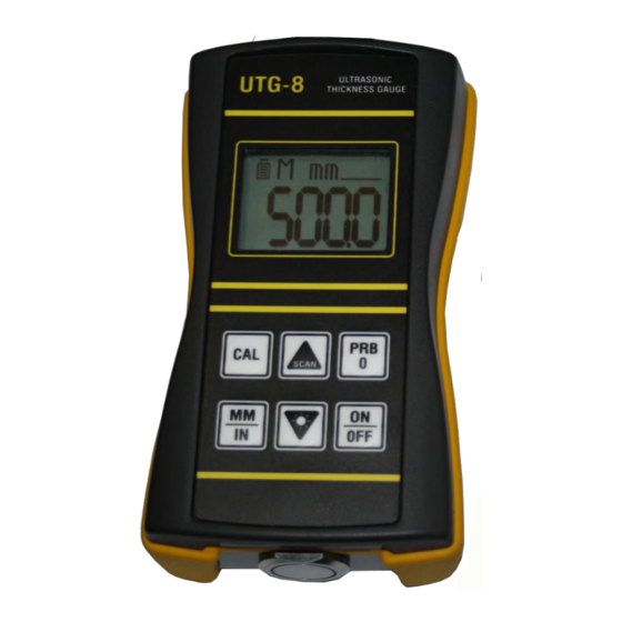
COMPOSITION AND OPERATION Outer appearance of the thickness gauge is illustrated on Fig. 1. Fig. 1 – Outer appearance of UTG-8 thickness gauge Functions of keys: « » - this key is used to turn the thickness gauge ON and OFF. - Page 8 The correctness of the above operation affects the measurement accuracy. “Zero” calibration procedure is detailed in para. 6.6 of this Manual. « » - the CAL key serves to enter and exit the calibration mode. This mode is used to adjust the ultrasound velocity value that will be applied for thickness calculation.
- Page 9 Display To show information on the display, the thickness gauge uses 4 main digits and some additional indicators, the functions of which are described below. Fig. 2 – Outer appearance of display When the gauge is displaying thickness measurements, the display will hold the last value measured, until a new measurement is made.
- Page 10 When the “m/s” symbol is on, the velocity of ultrasonic waves is measured in meters-per-second. Numeric (main) field of the display consists of five digits. This field is used to show numerical values, as well as simple words in different operation modes of the thickness gauge. When performing the manual thickness measurement, “M”...
- Page 11 “V” indicator appears during the calibration at a known ultrasound velocity in a test object. For details, please refer to para 6.7 of this Manual. “Prb0” symbol is on, after the zero calibration has been finished. For details, please refer to para 6.6 of this Manual. “Auto”...
- Page 12 Operation principle of the thickness gauge is based on ultrasonic pulse- echo method of measurement, which utilizes the property of ultrasonic waves to reflect from interface of media with different acoustic impedances. Piezoelectric plate of dual element transducer generates an ultrasonic pulse through a delay line (wedge) in the direction of outer surface of a product, whose thickness is to be measured.
- Page 13 – amplifier; – time interval meter; – power supply. Fig. 3 - Schematic structure of UTG-8 thickness gauge The thickness gauge can be operated in the following modes: − “Measurement” – basic operation mode of the gauge. The product thickness is measured in this mode;...
- Page 14 Design Electronic circuit of the thickness gauge is assembled on a PCB, housed in a plastic case. Power supply source comprised by three (3) ‘ААА’ battery cells is placed inside the case. The bottom panel of the case includes a 5-mm thick probe disc (Fig. 4). The top panel of the case includes connectors for transducers (Fig.
-
Page 15: Setting-Up Procedure
SETTING-UP PROCEDURE Test object surface preparation In any ultrasonic measurement scenario, the shape and roughness of the test surface are of paramount importance. Rough, uneven surfaces may limit the penetration of ultrasound through the material, and result in unstable, and therefore unreliable, thickness measurements. - Page 16 be used in tightly confined areas. Besides, the choice of a transducer can also be affected by the curvature of tested surface, since the establishment of ultrasonic contact between a transducer and tested surface is of paramount importance while making the measurements. The choice of a proper transducer often becomes an issue of finding a compromise between different characteristics.
- Page 17 If the gauge is not "zeroed" correctly, all measurements the gauge makes will be erroneous by some fixed percentage. When the UTG-8 is "zeroed", this fixed error value is measured and automatically corrected for in all subsequent measurements.
- Page 18 Note - Zero calibration of the thickness gauge should be performed only on the built-in 5mm thick probe disc. Remove the transducer from the probe disc and press button. After that, the display will show a message (Fig. 8) about the successful zero calibration, along with a shortly-displayed measured value of ultrasound propagation delay in the transducer wedge (in µs), which will be used for subsequent measurements.
- Page 19 symbol illuminated, and the main indicator will show the ultrasound velocity value (Fig. 9). Fig. 9 4) Using keys, adjust the displayed velocity up or down, until it matches the actual (true) ultrasound velocity of the material to be measured. 5) Press key once again to exit the calibration mode.
- Page 20 5) Press key, after which the main indicator will show the thickness value, the “H1” symbol will appear on the display, and the “mm” symbol will start flashing. 6) Remove the transducer from the sample piece. 7) Using keys, adjust the displayed thickness up or down, until it matches the actual (true) thickness of the sample piece.
- Page 21 4) Press key on the keypad, after which the main indicator will show some (probably incorrect) thickness value, the “H1” symbol will appear on the display, and the “mm” or “in” symbol will start flashing (Fig. 11). Fig. 11 5) Remove the transducer from the 1 sample piece.
- Page 22 12) Press key, after which the “2-OK” symbol will appear on the display, and on the display for a short period of time will appear the calculated wedge delay along with ultrasound velocity. Note - After the two-point calibration is completed, the ultrasound velocity and wedge delay values will be saved to the memory of the thickness gauge to be used for further measurements.
-
Page 23: Operation Procedure
OPERATION PROCEDURE The thickness gauge is serviced by one operator. It is allowed to use the thickness gauge only after the present operation manual has been carefully read. Clean the surface, which comes in contact with the transducer, from flake scale, protective coating, paint, metal plating or other coarse micro-irregularities by mechanical scrubbing (using a wire brush, scraper, abrasive cloth strip or grinder). - Page 24 While the transducer is in contact with the material being measured, the UTG-8 is keeping track of the lowest measurement it finds. When the transducer loses contact with the surface for more than a second, the UTG-8 will display the smallest thickness it has found.
-
Page 25: Information About Manufacturer
Note - For more accurate measurement of ultrasound velocity, it is recommended that the thickness of sample piece exceed 20 mm. The procedure of ultrasound velocity measurement is detailed in para 6.8 of this Manual. INFORMATION ABOUT MANUFACTURER OKOndt GROUP www.oko-ndt.com E-mail: global-sales@oko-ndt.com...
Need help?
Do you have a question about the UTG-8 and is the answer not in the manual?
Questions and answers