
Related Manuals for OKOndt GROUP Eddycon C


Summary of Contents for OKOndt GROUP Eddycon C
- Page 1 Eddy current flaw detector Eddycon C Operating manual ЕС.14327992.03.13 OM Produced by LLC ”ULTRACON-SERVICE”...
-
Page 2: Table Of Contents
TABLE OF CONTENTS INTRODUCTION ............................3 1 PURPOSE ............................10 2 MAIN SPECIFICATIONS ....................... 11 3 DESIGN OF THE FLAW DETECTOR ..................12 Instrument appearance ......................12 Structural scheme ........................13 Appearance of the flaw detector screen................. 14 Menu structure ......................... 18 "TEST"... -
Page 3: Introduction
INTRODUCTION User manual of «Eddycon C» portable eddy current flaw detector (hereinafter referred to as "Flaw detector"), is intended for the study of operation principles of the flaw detector and its operating instructions, and includes the information on application, specifications, operating principle and structure, operating instruction, and also other information allowing a full-scale implementation of flaw detector technical capabilities. - Page 4 - Function keys. Respectively: "F1 NULL" – Balancing, "F2 DISP MODE" – different types of full-screen mode, "F3 ERASE" – erase and centering – in "TEST" menu; "F1 Load", "F2 Create/ Save","F3 Delete"– in "RESULTS"/"SETTINGS" submenu; "F1 An" (An - amplitude noise) – in "VIEW" menu; "F1 Add", "F2 Del", "F3 STD"–...
- Page 5 1 – Ethernet port for connecting a communication cable to PC; 2 – USB port for updating the flaw detector software and recording the testing results on the external Flash-Card Figure 2 – «Eddycon C» eddy current flaw detector. Rear panel...
- Page 6 Data + Common Left side panel of the flaw detector: 1 - LEMO jack for headphones with microphone connection; 2 - Charger connector; 3 - Switching On/Off the instrument. Figure 3 – «Eddycon C» eddy current flaw detector. Left side panel...
- Page 7 Table 3 – Description of LEMO jack for headphones with microphone connection Cont. Signal EGG.0B.304.CLL (front view) Input signal from the microphone Right audio output Common Left audio output Table 4 – Description of charger connector Cont. Signal EGG.1B.304.CLL (front view) Charging device –...
- Page 8 2 - Connector for eddy current probe (ECP) and eddy current rotary scanner; 3 - Encoder (Enc) connector Figure 4 – Eddycon C eddy current flaw detector. Right side panel Table 5 – Description of single (parametric) eddy current probe (ECP) connector Cont.
- Page 9 Table 6 – Description of encoder (Enc) connector Cont. Signal Positive signal input "A" Lemo EGG.1B.308CLL Power "+5V" (front view) Negative signal input "Z" Positive signal input "Z" Negative signal input "B" Positive signal input "B" Negative signal input "A" Common Table 7 –...
-
Page 10: Purpose
PURPOSE 1.1 The flaw detector is intended for manual and mechanized testing by eddy current method for the presence of surface and subsurface defects, such as material discontinuity (cracks, laps, cissings, fine cracks etc.), for conductivity and thickness measuring. 1.2 The flaw detector can be applied for the testing of products during their manufacture and operation by NDT services and laboratories of enterprises that provide the products quality control. -
Page 11: Main Specifications
MAIN SPECIFICATIONS 2.1 Range of operating frequencies adjustment – from 10 Hz to 16 МHz. 2.2 Setup max. sampling frequency/digitizing rate – 10 kHz/10000 samples per second (max). 2.3 Setup of the range of adjustment of ECP excitation signal voltage (double amplitude) –... -
Page 12: Design Of The Flaw Detector
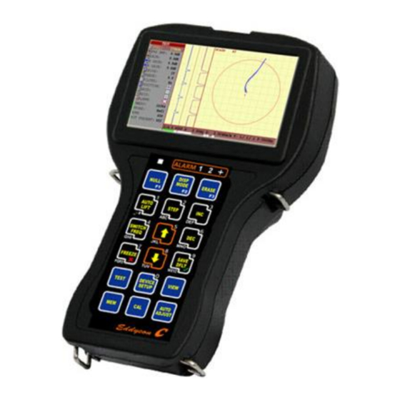
DESIGN OF THE FLAW DETECTOR 3.1 Instrument appearance Instrument appearance is shown in Figure 5. Display screen Keypad Figure 5 – «Eddycon C» eddy current flaw detector... -
Page 13: Structural Scheme
3.2 Structural scheme Structural scheme of the flaw detector Figure 6 – Structural scheme of the flaw detector Structurally, the flaw detector consists of: a) casing and cover plate with the membrane keypad, indicators of ALARM and overloading, Mini-USB port for connection to PC, USB port for external flash-card connection, charger connector, headphones and microphone;... -
Page 14: Appearance Of The Flaw Detector Screen
3.3 Appearance of the flaw detector screen Appearance of the flaw detector screen is shown in Figure 7. Navigation menu Working field Bottom horizontal field Figure 7 – Display appearance after switching On the flaw detector Working filed in the testing mode is divided in 3 areas of signal reflection and display area title: ... - Page 15 o RPM – rounds per minute for the eddy current rotary scanner; o ROT PRESENT– type of connected rotary eddy current scanner. The flaw detector displays two time charts of time dependence of signal and eddy current signal which is displayed in a complex plane for the selected frequency.
- Page 16 The most suitable option is one in which the two parameters do not exceed, or exceed but not significantly the 50 %. Operation in mode, in which one of the parameters exceeded the threshold of 90 % is unacceptable and requires the adjustment of flaw detector parameters. Lightning of a left overload indicator (pos.
- Page 17 "ALARM" menu setup This menu allows setting of ALARM (automatic flaw alarm). There is a possibility to setup ALARM for each frequency and mix. ALARM itself is the response of flaw detector to the event occurring at crossing or non-crossing of alarm frame (threshold level) by a signal.
-
Page 18: Menu Structure
Figure 11 – Circuits of PROBE connection 3.4 Menu structure MENU TEST ALARM SETTINGS VIEW RESULTS ARCHIVE SETTINGS CALIBRATION Figure 12 – Menu structure... -
Page 19: Test" Menu
Navigation of the menu map described below is performed with the help of the following keys: The instrument menu is divided in five inserts: "TEST", "SETTINGS", "VIEW", "ARCHIVE", "CALIBRATION", the first and the fourth ones are also divided in submenus. 3.5 "TEST"... - Page 20 Quick selection "TEST", "SETTINGS", "VIEW", "ARCHIVE", "CALIBRATION" inserts is carried out by pressing keys. "Hot keys" which are operated by "F1", "F2", "F3" function keys are situated on the keypad of the flaw detector: F1 (Balancing) – to balance the signal, place it in the screen center −...
- Page 21 Here you adjust the test frequency of the probe that is connected to the instrument. The frequency depends on the probe you use and the application at hand. You can select the frequency between 10 Hz and 16 MHz. 2 " PRE AMP"...
- Page 22 Averaging Filter Switching on of the averaging filter "AVRG" sets a number of points N to be averaged from 2 to 127 points with a step of 1, 10, 100 points. Can be used when working with high gains and scales to reduce noise signal by smoothing Differential Filter Switching on of a differential filter “Diff”...
- Page 23 High-Pass Filter Switching on of a high-pass filter activates the field for setting up the frequency HF from 1 to 5000 Hz with a step of 1, 10, 100, 1000 Hz. The frequencies from the set value of Hz to F /2 Hz (where F –...
- Page 24 Note. Only one filter can be set in the frequency selected by an operator. Activation of other filter makes the earlier selected filter inactive within the set frequency. " " - selection of the position of complex plane center. Can be set in the following positions: - complex plane center, - in the right center of...
- Page 25 Where XCi, X1i, X2i – horizontal components of the mix of the 1 and 2 frequencies, respectively; YCi, Y1i, Y2i – vertical components of the mix of the 1 and 2 frequencies, respectively; M1, M2 – scales of the 1 and 2 frequencies, respectively.
- Page 26 Figure 15 – Setup of "Type: " of threshold level "H:" parameter variation allows change the height of the threshold level. Parameter variation is carried out in the range from 0 to 32768 with a step of 1, 10, 100, 1000, 10000 (see Figure 15). ...
- Page 27 " :" parameter variation allows change turning angle of threshold level relative to the complex plane center. Turn angle variation is carried out in the range from 0˚ to 359˚ with a step of 1˚, 10˚, 100˚ (see Figure 16). "...
-
Page 28: Guidelines For Overload Processing
"Y2:" parameter variation allows changing the angle position of threshold level in Y2-direction. Y2 parameter variation is carried out in the range from 32768 to - 32768 with a step of 1, 10, 100, 1000, 10000 (see Figure 17). Select the frame polarity "Pol:" which makes the alarm trigger: –... -
Page 29: Conductivity" Mode
Conductivities of metals at ambient temperature are typically in the range of 1 to 60 MegaSiemens per meter. The Eddycon C measures the conductivity of non-magnetic metals and alloys in the range 0.8 to 110.0 % IACS. It uses the Eddy Current technique for measuring the conductivity of materials in % IACS, or MSiemens/meter. - Page 30 To connect the flaw detector with Cable and the eddy current probe CP- 13 for measuring the electrical conductivity. To press the button for entering the instrument menu «SETTINGS» and to choose «Test mode» - «CONDUCTIVITY». Figure 18 – «CONDUCTIVITY» Test Mode To press to enter the «TEST»...
- Page 31 To determine the material by its conductivity the setting up samples should generate the range of the conductivity, wherein the first sample value is lower and the second sample value is higher than the conductivity of the material being measured. Conductivity measurement tolerances are: ...
- Page 32 [0,5 mm]), set the eddy current probe on the sample and press Figure 22 – Entering the gap value for setting on the Cond 1 sample Measuring Conductivity and Coating Thickness with the Eddycon C Guidelines for successful operation: For accurate measurement of conductivity the surface coating thickness should be 0.5 mm (0.020 inches).
-
Page 33: General Settings" Menu
Measurement close to edges and on thin materials may give erroneous results. Check on a known consistent material to establish the influence of these effects. The coating thickness measurement function does not require further calibration, it should be accurate to better than 10 % of the displayed value on base materials having a conductivity between approximately 1 % and 100 % IACS. -
Page 34: View
- "Сolor scheme" – 1. "Light" - for operation with faint outer lighting; 2. "Dark" - for operation with intense outer lighting; 3) "Standard" – standard scheme. - "Brightness" – display brightness in % - from 10 to 100 with a step of 10%;... - Page 35 Note. To view previously saved testing results, it is necessary to press key, choose the "RESULTS" submenu and press key. Then, move the cursor to the certain result and press key – "F1 Load". Then, an automatic enter in "VIEW" is carried out. Position “Position”...
-
Page 36: Archive" Menu
moving the cursor to the next signal from defect, the data corresponding to the marked defect will be displayed on the screen. The depth of the defect will be displayed only if the correct calibration curve is created! 3.10 ARCHIVE menu "... -
Page 37: Settings" Menu
Figure 26 – "RESULTS" menu. List of catalogues and files Note. To prevent an accidental deleting of catalogues with useful information, the flaw detector has a protection, which allows only empty catalogues deleting. In order to delete the catalogues, firstly you need delete its contents. -
Page 38: Set Up Of "Calibration" Menu
After the setups file loading, automatic enter in "Testing" menu is carried out. Figure 28 – "SETTINGS" menu 3.13 Set up of CALIBRATION menu " " The calibration curve plotting will be illustrated using the calibration block 2353.08. To plot the calibration curve, it is essential to set up all parameters of the flaw detector for operation with a specific probe (i.e. - Page 39 Figure 29 – Appearance of defectogram for the calibration curve plotting After the acquisition of defectogram, press key, for the quick transition to "CALIBRATION" menu. 1 - Set a curve for evaluation of the defect depth (Amplitude, Phase); 2 - Select the units of defect measurement (mm, %); 3 - Calibration block selection;...
- Page 40 Before plotting the calibration curve it is necessary by the keys, to move to the "CURVE POINTS: " item position "1) " and by the F2 key, delete all points of previous calibration curve (see Figure 30). Select the type of measurement in the cursor "Type" – Pk-Pk. Move to the "Position: "...
-
Page 41: Communication With Pc
3.14 Communication with PC The flaw detector in a set with "Eddycon C" software ensures communication mode with a PC for the information input to the PC from the flaw detector memory (testing results, operating setups) and the possibility to print out this information and to form a report. - Page 42 (by default the "RESULTS" folder is proposed, saved on the hard disk drive of PC in the program directory of «Eddycon C»). This file can be located in the flaw detector memory or also be stored on hard disk drive of PC (if previously copied to the hard disk drive (3.14.3.2)).
- Page 43 – "Selecting the interface language" window Note – Reload the program to change the interface language. Select "Exit" subitem to finish the "Eddycon C" program. When selecting "Report" item of the main menu, there appears a window for filling in the report form of the testing carried out (Figure 36).
- Page 44 Figure 36 – Report form of a testing carried out After pressing button, there appears a window to preview the testing protocol. There is an option to select between: weather to print out the setting parameters of the flaw detector or not. To abstain from printing out the flaw detector settings, put a tick in front of "Disable setting".
- Page 45 3.14.2.3 Time diagram area Two diagrams of signal to time dependence are displayed in time diagram area (item 3, Figure 32). 3.14.2.4 Signal display area (active area) In the display area of eddy current signals is displayed the eddy current signal, which is represented by an image in the complex plane for the frequency selected (item 4, Figure 32).
- Page 46 Figure 38 To change the cursor position it is required to place the "mouse" cursor onto the center of a measuring cursor (item 2, Figure 38), and when there is a cursor, move the measuring cursor to the required position by holding the left mouse button down.
-
Page 47: Working With The Program
PC using a USB cable (item 3.14.3.1). In the menu of «Eddycon C» program select the item "Loading", and after, in the program window there are displayed the files of all the testing results stored in the flaw detector memory. - Page 48 In the window that appears, choose the path to removable media – the flaw detector memory or the path where previously there was stored data on PC, move the cursor to the necessary file with the testing results and click "Open".
-
Page 49: Labeling And Sealing
LABELING AND SEALING 4.1 The flaw detector labeling complies with the manufacturer’s set of documents and includes: manufacturer’s name and trade mark; name and designation of the flaw detector; year and quarter of manufacture; serial number; designation of specifications (TU);... -
Page 50: Composition And Delivery Set
5.1 The flaw detector comprises Basic delivery set consisting of the following components: Table 8 Name and reference designation Quantity Electronic unit of Eddycon C eddy current flaw detector (Lemo 16) 1 pc. Connecting cable Lemo16 – Lemo04 3 pcs. (electronic unit / ECP, Bridge) 1800 mm Eddy current probe WLD100K3×.35DA0... -
Page 51: Safety Measures
SAFETY MEASURES 6.1 In operation with the flaw detector, it is necessary to observe the safety measures while charging the storage battery unit of the flaw detector by means of automatic charger. 6.2 In operation with the flaw detector an operator should be governed by the safety standards in effect at the enterprise. -
Page 52: Reflection, Differential Probe
8.1.9 Increasing the gain on preamplifier and amplifier should maximize the signal amplitude, but at the same time monitor behind parameters of the input circuit. 8.1.10 After changing any parameter that affects the absolute value of the signal it is necessary to perform balancing by pressing key. -
Page 53: Rotation Probe
the defect will be triggered on the flaw detector keypad (digital indicators on the display) and sound alarm (if it has not been turned off in "SETTINGS" menu). ROTATION PROBE 8.3.1 Connect the rotary scanner to the flaw detector using the connection cable. - Page 54 8.3.18 Select the Bandpass filter and perform it`s setting. First of all, minimize the distortion signals from ECP in the hole by setting the "LB" parameter, and then proceed the "HB" setting. The filter is set by trial and error. 8.3.19 During the ECP rotation in a hole perform the ALARM setup.
-
Page 55: Maintenance
MAINTENANCE 9.1 The flaw detector maintenance includes the maintenance inspection, operating repair and calibration. 9.2 Intervals between the maintenance inspections are set depending on the industrial conditions, but no less than once per month. Connecting cable fixation, condition of controls and indicators are checked during the maintenance inspection. -
Page 56: Typical Failures And Troubleshooting
Figure 41 9.4.4 Battery pack mounting is carried out strictly in reverse order. 10 TYPICAL FAILURES AND TROUBLESHOOTING 10.1 The list of the most common and probable failures is given in Table 9. Table 9 – Typical failures and troubleshooting Failure Probable cause Remedy... -
Page 57: Transportation And Storage
TRANSPORTATION AND STORAGE 11.1 Climatic conditions for the flaw detector transportation is at temperature range from minus 25 °С to plus 50 °С. 11.2 Transportation of the packed eddy current flaw detector may be shipped by any type of closed transport (except for the sea one) that protects the eddy current testing system from direct impact of precipitations, with a possibility of transshipping from one type of transport to the other. -
Page 58: Acceptance Certificate
ACCEPTANCE CERTIFICATE “Eddycon C” eddy current flaw detector with serial number №_________ meets the requirements of specification ЕС.14327992.03.13 RE and is considered to be suitable for operation. Person responsible for acceptance _______________ /_________________________/ S.P. Date of manufacture ________________20____... - Page 59 APPENDIX A REQUIREMENTS TO CHARGING DEVICE FOR PORTABLE EDDY CURRENT FLAW DETECTOR «EDDYCON C» Special-purpose charging device for Li-Ion battery charging (3 elements) with rated voltage of 12 V and capacity of 4.5 Аhour. Charge type – accelerated. Charge rate – (2.3 ± 10 %) А.
- Page 60 APPENDIX B EDDY CURRENT PROBES FOR THE FLAW DETECTOR EDDYCON C Table B.1 Sizes of Operating Overall № ECP type working frequency, Detected flaws dimensions, mm surface, mm dimensions, кHz SS1.5M05DA0 Ø5 500 - 2000 Ø 13 35 Surface defects in different conductive SS650K06DA0 Ø...
- Page 61 Table B.1 10 SU450K05DA0 Ø 5 400 - 600 Ø 12.5 70 Surface cracks in aluminum alloys, ferromagnetic and austenitic steels and 11 SU450K5А05DA0 Ø 5 400 - 600 Ø 12.5 135 etc. Ø 9,6 55 12 SU1.8М3.5DS01 Ø...
- Page 62 Table B.1 Testing for the presence of surface cracks in a metric thread with a step of 1,5 mm 6 0.5 Ø 12 61 19 SU350K6x0.5DA4 350 - 600 made on products made of ferromagnetic material. Used with the SK-MR-04 Testing for the presence of surface cracks in a metric thread with a step of 5,08 mm 20 SU350K6x0.5DA5...
Need help?
Do you have a question about the Eddycon C and is the answer not in the manual?
Questions and answers