
Subscribe to Our Youtube Channel
Related Manuals for Intrepid Control Systems neoOBD2-SIM


Summary of Contents for Intrepid Control Systems neoOBD2-SIM
- Page 1 User’s Guide Version 1.0 - March 11, 2019 © 2019 Intrepid Control Systems, Inc.
- Page 2 User’s Guide Version History Version Date Description / Major Changes Number 2019/03/11 Initial release. Version 1.0 - March 11, 2019 © 2019 Intrepid Control Systems, Inc.
-
Page 3: Table Of Contents
Sending the Script for Coremini Mode.....................10 Troubleshooting ............................Possible Problems and Solutions ......................12 Support Contact Information ........................ICS United States Headquarters ......................13 4.2 ICS International Offices .......................... 13 Version 1.0 - March 11, 2019 © 2019 Intrepid Control Systems, Inc. -
Page 4: Introduction And Overview
The neoOBD2-SIM uses Vehicle Spy Professional or Enterprise software to create custom simulations that make the neoOBD2-SIM act like an ECU, an OBD port, a vehicle, or an industrial device. This is accomplished using a simple scripting interface called Function Blocks. -
Page 5: Operational Overview
User’s Guide Figure 1: neoOBD2-SIM Package Contents If anything is missing or damaged, please contact Intrepid Control Systems for assistance. The contact for your locale can be found at https://www.intrepidcs.com/worldwide. 1.3 Operational Overview The device can be powered using the built-in 2000 mAh Lithium Ion battery, the 12V power supply, or the USB Type-C cable. - Page 6 Important Note: When updating the device firmware, DO NOT UNPLUG THE DEVICE. Unplugging the device during a firmware update will result in irreparable damage to the neoOBD2-SIM. If the neoOBD2-SIM is damaged, the device must be returned to Intrepid Control Systems for repairs. When modifications are complete, press Write Settings to write the changes to the device. Please note that changing settings on the device will not clear any scripts present on the device.
-
Page 7: Summary Of Key Features
User’s Guide 1.4 Summary of Key Features The neoOBD2-SIM includes two CAN / CAN FD channels and is designed for complex script- based simulations for interactive protocols such as ISO 14229, CCP/XCP, J1939, and more. Construction, Controls, and Cabling 1. -
Page 8: Hardware And Software Requirements
1.5 Hardware and Software Requirements Hardware: The neoOBD2-SIM is programmed through Intrepid Control Systems’ Vehicle Spy 3 software. All commands are executed on the device using the CoreMini scripting engine. CoreMini scripts are written using Function Blocks inside of Vehicle Spy. -
Page 9: Building Coremini Scripts Using Vehicle Spy
2.2 Basic Commands For now, the focus is going to be on the more commonly used commands. Additionally, there will be more info regarding options and commands that are unique to the neoOBD2-SIM. Set Value Set Value is used to update variables and signals inside of Vehicle Spy. Its use is extremely common. - Page 10 (CW / CCW), then press Add to Expression. This will add the code to the Expression section. Value To Set will contain the App signal or Tx Message Signal that’s being set Version 1.0 - March 11, 2019 © 2019 Intrepid Control Systems, Inc.
- Page 11 Figure 6: Wait Until Step LCD Display The neoOBD2-SIM also has a LCD display that can also be used to display text. The LCD display consists of four lines with twelve characters each. When a line is full, but more characters are in the command, the remaining characters will be truncated.
- Page 12 Evaluate as Text box is checked, Message and Application signals can be inserted in-line. See below: Figure 8: Log Data Expression Showing App Signal With the example in Figure 8, the neoOBD2-SIM will show “Param2: 0” on the LCD screen. Transmit This is the command used to send a message onto the bus.
-
Page 13: Leds
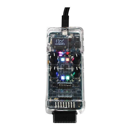
User’s Guide Figure 9: Transmit Command 2.3 LEDs The neoOBD2-SIM also has four multicolored LEDs that are programmable using the Set Value command. By default, the LEDs run in an automatic mode that shows different colors under certain circumstances, such as when the device is in bootloader mode while reflashing firmware. To use the LEDs, the first step is to turn the Auto function off. Simply set the Auto property of each LED to 0. - Page 14 Any errors with the script will be noted in the build tab of the CoreMini console with red LEDs. Yellow LEDs note warnings that may affect functionality. Green LEDs mean all is well. Once ready, press Send to load the script onto the neoOBD2-SIM. Version 1.0 - March 11, 2019 © 2019 Intrepid Control Systems, Inc.
-
Page 15: Troubleshooting
Problem: The script was pushed to the device, but does not seem to be running in Standalone mode Solution: Make sure that the USB cable is unplugged from the neoOBD2-SIM when the device is ready to be used. If the USB is plugged in when the device is booted, the CoreMini script will not run. -
Page 16: Support Contact Information
4.2 ICS International Offices UK Office Our UK office can be reached as follows: Phone: +44 24 7718 0296. Email: ics_uk@intrepidcs.com European Union Office For support in the EU, please contact Intrepid’s Germany office: Phone: +49 721 6633703 -4. Fax: +49 721 6633703 -9. Email: icsgermany@intrepidcs.com Version 1.0 - March 11, 2019 © 2019 Intrepid Control Systems, Inc. - Page 17 We can also be contacted in Shenzhen: Phone: +86 0755-82723212. Email: icschina@intrepidcs.com India Office In India, please use this contact information: Phone: +91 +97 66 44 55 33. Email: IcsIndia@intrepidcs.com Version 1.0 - March 11, 2019 © 2019 Intrepid Control Systems, Inc.
- Page 18 User’s Guide Australia Office Our Australian office can be reached as follows: Phone: 03 9466 4948 (international callers: +61 3 9466 4948). Email: icsaustralia@intrepidcs.com Version 1.0 - March 11, 2019 © 2019 Intrepid Control Systems, Inc.
Need help?
Do you have a question about the neoOBD2-SIM and is the answer not in the manual?
Questions and answers