Table of Contents
Advertisement
Quick Links
Instruction Manual
Form 5088
October 2009
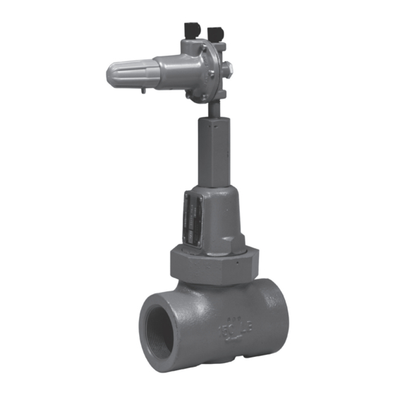
Type 1805P Pilot-Operated Relief Valve
!
Failure to follow these instructions or
to properly install and maintain this
equipment could result in an explosion
and/or fire causing property damage and
personal injury or death.
Fisher
regulators must be installed,
®
operated, and maintained in accordance
with federal, state, and local codes, rules
and regulations, and Emerson Process
Management Regulator Technologies,
Inc. instructions.
If the regulator vents gas or a leak
develops in the system, service to the
unit may be required.
Failure to correct trouble could result
in a hazardous condition. Call a gas
service person to service the unit. Only
a qualified person must install or service
the regulator.
Introduction
Scope of the Manual
This manual describes and provides instructions for
the installation, adjustment, maintenance, and parts
ordering information for the Type 1805P pilot-operated
relief valve. Instructions and parts lists for any other
Fisher equipment mentioned in this instruction manual
are found in separate manuals.
Description
The Type 1805P pilot-operated relief valve is used to
provide protection from overpressuring a downstream
system. This relief valve is suitable for service on
natural gas, air, propane, or any other operating
WaRnIng
www.fisherregulators.com
W6913
Figure 1. Type 1805P Pilot-Operated Relief Valve
medium not corrosive to the internal parts. Very little
build-up over the set pressure is required for the main
valve to go wide-open for maximum relief capacity.
Smooth opening action minimizes system pressure
surges during emergency action.
Specifications
Some of the specifications for a given relief valve as
it comes from the factory appear on the nameplate
attached to the Type 1805 main valve spring case.
Other specifications appear on the Type 6358B pilot
spring case.
Type 1805P
Advertisement
Table of Contents

Related Manuals for Emerson Fisher 1805P Series


Summary of Contents for Emerson Fisher 1805P Series
- Page 1 ® operated, and maintained in accordance with federal, state, and local codes, rules and regulations, and Emerson Process Management Regulator Technologies, Inc. instructions. If the regulator vents gas or a leak develops in the system, service to the unit may be required.
-
Page 2: Specifications
Type 1805P Specifications Body Size and End Connection Style IEC Sizing Coefficients 2 NPT : 0.91 : 0.44 Maximum Relief (Inlet) Pressure (1, 2) : 0.89 50 psi (3,4 bar) over relief pressure setting or 150 psig (10,3 bar), whichever is lower Pilot Control Line and Vent Connections 1/4 NPT Relief Set Pressure Ranges... -
Page 3: Principle Of Operation
Type 1805P A6919_1 TYPE 1805P RELIEF VALVE A6919_1 TYPE 1805P RELIEF VALVE PILOT TO MAIN VALVE TO MAIN VALVE CONTROL DIAPHRAGM DIAPHRAGM SPRING ADJUSTING TO MAIN VALVE TO MAIN VALVE SCREW DIAPHRAGM DIAPHRAGM DIAPHRAGM DIAPHRAGM ASSEMBLY ASSEMBLY DIAPHRAGM TO EXHAUST PORT DIAPHRAGM TO EXHAUST PORT LOCKNUT... -
Page 4: Overpressure Protection
Type 1805P Before installing, inspect the main valve and pilot for 150 psi (10,3 bar). The individual spring range of your any shipment damage and any foreign material. Make relief valve is stamped on the nameplate. System sure that the valve is oriented so that pipeline flow is operation within these limitations does not eliminate the in the same direction as indicated by the arrow cast on possibility of damage from external sources or debris in... -
Page 5: Maintenance
Type 1805P 1. Loosen the locknut (key 11, Figure 4). 3. Unscrew the union nut (key 16) and remove it with the spring case (key 13), spring (key 11), and 2. Turn the adjusting screw (key 10) clockwise to spring seat (key 12). increase or counterclockwise to decrease the relief 4. -
Page 6: Parts Ordering
Type 1805P Assembly 8. Install the spring case (key 2) on the body (key 1) with the vent assembly (key 16) oriented to 1. If removed, install the body plug O-ring (key 13) prevent clogging or entrance of moisture. over the body plug (key 3), and install the body plug Install the machine screws (key 17) and tighten in into the body (key 1). - Page 7 Type 1805P ANTI-SEIZE BE9481-C B1128 Figure 3. Type 1805P Main Valve Assembly Type 6358B Pilot (Figure 4) Description Part number Description Part number Pilot Body, Aluminum 39A0138X012 Locknut 1A946324122 Spring Case, Aluminum 25A6220X012 Closing Cap 23B9152X012 Body Plug, Aluminum 1B797509032 Body Plug Gasket or O-ring Valve Plug and Stem Assembly Nitrile (NBR)
- Page 8 For further information visit www.fisherregulators.com The Emerson logo is a trademark and service mark of Emerson Electric Co. All other marks are the property of their prospective owners. Fisher is a mark owned by Fisher Controls, Inc., a business of Emerson Process Management.