Advertisement
Quick Links
APPLICABLE DOCUMENTS:
DOC
DRAFTER
LVL
A. MANGIAMELI
CHECKER
3
J. BROWN
2
ENGINEER
A. MANGIAMELI
1
RLS TO PROD
REV
01
ECN-36327:UPDATE FIGURES;
CHANGE NAME TO TTH, UPDATE
EARCUSHION SECTION
01A UPDATE TO INCLUDE TTH S2
01B UPDATED TTHS2 TT BATT. LIFE TO 240
HRS.
01C UPDATED TTHS2 VOLT. RANGE
01D VARIOUS UPDATES
DATE
02/05/04
DESCRIPTION
02/27/04
02/05/04
SIZE
A
REVISIONS
DESCRIPTION
FRAMINGHAM, MA 01701-9168
MANUAL, OPERATING &
MAINTENANCE (TTH & TTH Series 2)
FSCM
CLASS
DWG NO.
32108
RF
CLASS
DWG NO.
RF
273139
CHECK
ENG
DATE
VAB
AM
11/04
AM
07/10
AM
09/10
AM
07/11
AM
10/11
REV.
273139
01D
SHT 1 OF 25
Advertisement

Related Manuals for Bose TriPort TTH


Summary of Contents for Bose TriPort TTH
- Page 1 CLASS DWG NO. 273139 REVISIONS DESCRIPTION CHECK DATE ECN-36327:UPDATE FIGURES; 11/04 CHANGE NAME TO TTH, UPDATE EARCUSHION SECTION 01A UPDATE TO INCLUDE TTH S2 07/10 01B UPDATED TTHS2 TT BATT. LIFE TO 240 09/10 HRS. 01C UPDATED TTHS2 VOLT. RANGE 07/11 01D VARIOUS UPDATES 10/11...
-
Page 2: Headset Features
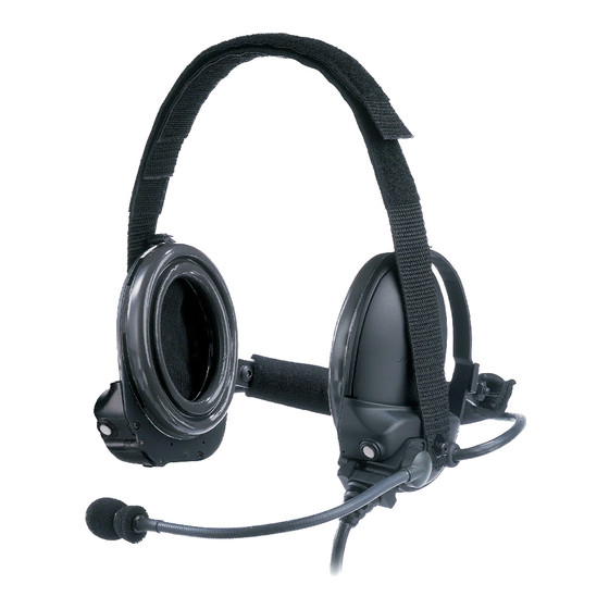
HEADSET FEATURES ® ® The Bose TriPort Tactical Headsets (TTH & TTH Series 2) are active noise reduction (ANR) communication headsets intended to be used by military passengers of wheeled combat vehicles. The TTH headsets include an earcup assembly (earcups and napeband) and a cable/microphone assembly. -
Page 3: Technical Information
TECHNICAL INFORMATION TTH Series 2 Headset can be donned and doffed without removing helmet. Cable/boom microphone assembly is replaceable and can be positioned on left or right side. Mono and stereo versions available. Weight (on head) 16 oz. maximum Same Spring force (on head) 1.8 lbf. - Page 4 HEADSET CONNECTORS AND CONTROLS The connectors and controls for the TTH and TTH Series 2 headsets are integrated into the cable/microphone assembly normally attached to the left earcup of the headset. The assembly may be mounted on the right earcup if desired. The control module on the cable/microphone assembly has a three-position push-to- talk (PTT) switch as well as a two-position talk-thru circuit (TTC) switch as shown in Figure 2.0b and 2.0c.
- Page 5 Figure 2.0b TTH Control Module Features COMPONENT FUNCTION Microphone Boom and Cable Assembly Transmits user’s voice into intercom or radio channel PTT Switch Used when transmitting on and listening to intercom channel or radio. The latched position allows the user to communicate on the vehicle intercom. The OFF (center position allows the user to listen only.
- Page 6 In addition to offering all of the same features as the TTH, the TTH Series 2 has been redesigned for better ergonomics with an integrated attachment clip. Figure 2.0c TTH Series 2 Control Module Features COMPONENT FUNCTION Microphone Boom and Cable Assembly Transmits user’s voice into intercom or radio channel PTT Switch...
- Page 7 Vehicle Interface Connector Physical Appearance Connection Desc. Pin-out TTH Series 2 Function Shield Ground (power and audio) Monaural Boom mic Ground** Left/Right earcup audio Boom mic Signal** Power Prior to Function Shield Shield Contact Right earcup audio Ground (power and audio) Binaural Boom mic ground**...
-
Page 8: Headset Troubleshooting
HEADSET TROUBLESHOOTING START PHYSICAL DAMAGE OR REFER TO HEADSET DETERIORATION PRESENT? INSPECTION TABLE REPLACE TTC CAN AUDIO BE IS FAULT STILL BATTERY HEARD THRU TTC? PRESENT? (pg 14) SUBSTITUTE CABLE / MICROPHONE ASSEMBLY WITH KNOWN WORKING (pg 13) IS FAULT STILL CONNECT HEADSET PRESENT? TO KNOWN WORKING... - Page 9 Headset Inspection Table Component Condition Corrective Measures Earcup Assembly Check for cracks and other visible damage to the Replace earcup assembly* housing. Napeband Check for visible damage. Replace earcup assembly* Earcushions Check for visible cuts. Check that uniform Replace earcushions.* pressure does not cause bottoming against earcup.
- Page 10 HEADSET COMPONENTS REMOVAL AND REPLACEMENT PROCEDURES Moving Cable/Microphone Assembly to Opposite Earcup a. Removal 1. Using cross-tipped screwdriver loosen three captive screws (3) securing cable/microphone assembly (2) to earcup assembly (1) and the decorative cover (5) to opposite earcup assembly (1). 2.
- Page 11 Earcushion and Scrim Removal and Replacement CAUTION Do not attempt to remove the earcushion by pulling on the soft earcushion material. Figure 4.2 Earcushion and Scrim Removal and Replacement a. Removal 1. Remove earcushion (1) from earcup assembly (3) by inserting fingers inside earcup between scrim (2) and earcushion and firmly pulling out.
- Page 12 Windscreen and O-ring Removal and Replacement Figure 4.3 Windscreens and O-ring Removal and Replacement a. Removal 1. Grasp O-ring (2) between thumb and forefinger and slide O-ring (2) and windscreen (3) off microphone (1). 2. Separate O-ring (2) from windscreen (3). CAUTION When placing windscreen/O-ring on microphone, be careful not to tear windscreen.
- Page 13 Overhead Strap Assembly Removal and Replacement NOTE The overhead strap assembly consist of two hook and loop strap sections, hooks and loops. When placing a single strap at a time make sure the replacing strap is the same as the one being removed.
- Page 14 Cable/Microphone Assembly Removal and Replacement a. Removal 1. Using cross-tipped screwdriver loosen three captive screws (3) securing cable/microphone assembly (2) to earcup assembly (1). Unplug connector connecting the cable/microphone assembly (2) to the jumper cable coming off the earcup printed circuit board and remove the cable/microphone assembly. b.
- Page 15 Alkaline Battery Removal and Replacement a. TTH Battery Removal and Replacement 1. Using flat-tipped screwdriver, loosen the captive screw on the battery cover and rotate to open the battery compartment. 2. Remove old battery and insert replacement battery positive end first into the battery compartment.
- Page 16 Attachment Clip Removed, Replacement or Adjustment (TTH Series 2 ONLY) a. Removal 1. Using a flat-tipped screwdriver loosen the captive screw securing attachment clip to the control module and remove clip from the control module. Control Module Attachment Attachment clip Clip captive screw b.
- Page 17 2. Position attachment clip on the control module in the desired orientation. Rotate the attachment clip 90 degrees in either direction, lining up the square feature on the control module with the square hold in the attachment clip. Attachment clip alignment feature 3.
- Page 18 Boom Microphone Removal and Replacement a. Removal 1. Using cross-tipped screwdriver loosen three captive screws (3) securing cable/microphone assembly (2) to earcup assembly (1). Unplug connector connecting the cable/microphone assembly (2) to the jumper cable coming off the earcup printed circuit board and remove the cable/microphone assembly. 2.
- Page 19 b. Replacement 1. Insert microphone through barrel of the plastic housing. Push replacement microphone with 2 new o-rings into the barrel of the plastic housing and secure in place with e-ring. 2. Plug 3-pin connector from the microphone assembly into the mating 3-pin connector on the cable assembly.
- Page 20 Appendix A Additional Technical Information SIZE FSCM CLASS DWG NO. SHEET REV. Framingham, MA 01701-9168 32108 273139 20 of 25...
- Page 21 Voltage Range The headset shall operate in one of three different modes as a function of the applied voltage. The operating modes shall be identified as “Unpowered”, “Low Power” and “Intercom”, and each mode shall be active with the voltage applied at the power contacts of the vehicle interface connector.
- Page 22 Low Power Mode Operation When operating in Low Power Mode the headset shall have the following current draw characteristics on the head in 85dBA red noise: Current Draw TTH Series 2 Less than 16mA RMS Less than 16mA and less than 180mA peak under any peak under any condition, except...
- Page 23 PTT Switch The PTT switch shall provide the following function at the vehicle interface connector: Switch Position Function Up, latching PTT line (contact #2) connected to ground (contact #3) through 470±5% ohms (power dissipation in this resistor is less than 0.1W) Center, latching PTT line (contact #2) open circuit Down, momentary...
- Page 24 Microphone preamplifier output (TTH only) This section is only applicable to TTH. The TTH Series 2 product design does not include an integrated microphone preamplifier output circuit. TTH ONLY: In the Intercom Mode the boom microphone preamplifier circuit shall provide an output capable of driving 200mVrms into an unbalanced load of 150±10% ohm AC impedance and not less than 300 ohms DC resistance.
- Page 25 Harmonic Distortion The harmonic distortion of the earphone assembly in Low Power and Intercom Modes shall not exceed 5% for a 0± 0.1dBV input at 500 Hz and it shall not exceed 10% with the input adjusted for an output of 100dB SPL at 500 Hz and then swept from 300 Hz to 4500 Hz.
Need help?
Do you have a question about the TriPort TTH and is the answer not in the manual?
Questions and answers