
Subscribe to Our Youtube Channel
Related Manuals for Sumitomo Invertek Drives Elevator Core


Summary of Contents for Sumitomo Invertek Drives Elevator Core
- Page 1 AC Variable Speed Drive for Geared and Gearless Elevators Elevator Core Installation & Operating Instructions...
-
Page 2: Typical Connection Diagram
ELEVATOR CORE USER GUIDE V0.02 - SHORTFORM.DOCX 1. Typical Connection Diagram Typical Connection Diagram www.InvertekDrives.com... -
Page 3: Table Of Contents
ELEVATOR CORE USER GUIDE V0.02 - SHORTFORM.DOCX 2. Contents 1. Typical Connection Diagram ......................2 2. Contents ............................. 3 3. Product Familiarisation....................... 4 3.1. Product Layout ..................................5 4. Checking Suitability of the drive....................6 4.1. Matching the drive to the Intended Power Supply ......................6 5. -
Page 4: Product Familiarisation
ELEVATOR CORE USER GUIDE V0.02 - SHORTFORM.DOCX 3. Product Familiarisation. ODL-3-240095-3F42-S-## Frame Size Supply Voltage 2 = 200…240 V AC 4 = 380…480VAC Output Current Rating For example, 0095 means 9.5 A. Number of Input Phases 1 = Single Phase input 3 = 3 Phase input F = Built-in EMC Filter 4 = Internal Brake Transistor... -
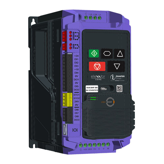
Page 5: Product Layout
ELEVATOR CORE USER GUIDE V0.02 - SHORTFORM.DOCX 3.1. Product Layout Power Supply Input Terminals USB-C Port Optional Universal Encoder Module Motor Connection Terminals Brake Resistor Connection Terminals RJ45 Port (NOT FOR ETHERNET!) Digital Inputs/Outputs Safe Torque-Off Inputs Drive Serial Number and Rating Digital, Analogue Inputs/Outputs Motor Brake Control Output Motor Contactor Control Output... -
Page 6: Checking Suitability Of The Drive
ELEVATOR CORE USER GUIDE V0.02 - SHORTFORM.DOCX 4. Checking Suitability of the drive. 4.1. Matching the drive to the Intended Power Supply Check the drive rating label to ensure it matches the intended power supply, the label shows the rated supply voltage and if the drive is suitable for single or 3-phase supply. For three phase supply models, a maximum of 3% imbalance is allowed between phases. -
Page 7: Electrical Installation
ELEVATOR CORE USER GUIDE V0.02 - SHORTFORM.DOCX 5. Electrical Installation This manual is intended as a guide for proper installation. Invertek Drives Ltd cannot assume responsibility for the compliance or the non-compliance to any code, national, local or otherwise, for the proper installation of this drive or associated equipment. A hazard of personal injury and/or equipment damage exists if codes are ignored during installation. -
Page 8: Electrical Wiring Example For Geared System
ELEVATOR CORE USER GUIDE V0.02 - SHORTFORM.DOCX • If motor is not “inverter rated”. 5.2. Electrical wiring example for geared system. Electrical Installation www.InvertekDrives.com... -
Page 9: Electrical Wiring Example For Gearless System
ELEVATOR CORE USER GUIDE V0.02 - SHORTFORM.DOCX 5.3. Electrical wiring example for gearless system. Electrical Installation www.InvertekDrives.com... -
Page 10: Brake Resistor Connections
ELEVATOR CORE USER GUIDE V0.02 - SHORTFORM.DOCX 5.3.1. Brake resistor Connections The drive has an internal brake transistor fitted as standard and is enabled automatically when the regenerative energy from the load raises the drives internal DC bus to 390Vdc for the single and three phase 230V drives and 780Vdc for the 3 phase 400V drive. The brake resistor must be connected between the +DC and BR Terminals of the drive as shown in the images below, failure to do so can result in damage to the drive/Brake resistor. -
Page 11: First Start-Up Of Geared (Induction) Motors Without An Encoder
ELEVATOR CORE USER GUIDE V0.02 - SHORTFORM.DOCX 6. First Start-up of Geared (Induction) Motors without an Encoder. The below procedure illustrates a method for commissioning the drive in a typical elevator application, it is assumed the drive has already been mechanically installed. 6.1. -
Page 12: Step 2- Pre-Power Checks
ELEVATOR CORE USER GUIDE V0.02 - SHORTFORM.DOCX 6.2. Step 2- Pre-Power Checks. Action/Checks Additional Information Check that all safety circuits/safety chains are in the correct state, failure to do so could result in damage to the equipment and possible injury or death. ... -
Page 13: Step 3- Apply Power
ELEVATOR CORE USER GUIDE V0.02 - SHORTFORM.DOCX 6.3. Step 3- Apply Power. Apply rated voltage to the ➢ If or is not shown refer to the troubleshooting section at the drive. back of the user manual. Check that the drive displays or . -
Page 14: Step 7 - Running The Elevator
ELEVATOR CORE USER GUIDE V0.02 - SHORTFORM.DOCX 6.6. Step 7 – Running the Elevator 6.6.1. Travel Curve for Geared (Induction) Motors without an Encoder. 6.6.2. Geared (Induction) Motors without an Encoder – Speed Loop Gains. First Start-up of Geared (Induction) Motors without an Encoder.www.InvertekDrives.com... -
Page 15: First Start-Up Of Geared (Induction) Motors With An Encoder
ELEVATOR CORE USER GUIDE V0.02 - SHORTFORM.DOCX 7. First Start-up of Geared (Induction) Motors with an Encoder. The below procedure illustrates a method for commissioning the drive in a typical elevator application, it is assumed the drive has already been mechanically installed. 7.1. -
Page 16: Step 1B- Encoder Wiring Connection Diagram
ELEVATOR CORE USER GUIDE V0.02 - SHORTFORM.DOCX 7.1.2. Step 1b- Encoder Wiring Connection diagram. Encoder P6-04 Shield Type Sin+ Sin- Cos+ Cos- CLOCK /CLOCK DATA /DATA Incremental Cable Shield Differential Incremental Cable Shield Differential Incremental Cable Shield Differential Incremental Cable Shield Incremental Cable... -
Page 17: Step 2- Pre-Power Checks
ELEVATOR CORE USER GUIDE V0.02 - SHORTFORM.DOCX 7.2. Step 2- Pre-Power Checks. Action/Checks Additional Information Check that all safety circuits/safety chains are in the correct state, failure to do so could result in damage to the equipment and possible injury or death. ... -
Page 18: Step 3- Apply Power
ELEVATOR CORE USER GUIDE V0.02 - SHORTFORM.DOCX 7.3. Step 3- Apply Power. Apply rated voltage to the ➢ If or is not shown refer to the troubleshooting section at the drive. back of the user manual. Check that the drive displays or . -
Page 19: Step 6 - Encoder Setup
ELEVATOR CORE USER GUIDE V0.02 - SHORTFORM.DOCX 7.6. Step 6 - Encoder Setup Action Additional Information Enter encoder pulses per revolution into P6-03 Refer to Encoder datasheet or nameplate. Enter Encoder Resolution P6-04 setting Encoder Type Incremental TTL- Differential 0 (Default) (A,/A,B,/B) (RS422) Incremental HTL-Differential... -
Page 20: Step 7 - Running The Elevator
ELEVATOR CORE USER GUIDE V0.02 - SHORTFORM.DOCX 7.7. Step 7 – Running the Elevator 7.7.1. Travel Curve for Geared (Induction) Motors with an Encoder. 7.7.2. Geared (Induction) Motors with an Encoder – Speed Loop Gains. First Start-up of Geared (Induction) Motors with an Encoder.www.InvertekDrives.com... -
Page 21: Commissioning Process For Geared (Induction) Motors With An Encoder
ELEVATOR CORE USER GUIDE V0.02 - SHORTFORM.DOCX 7.7.3. Commissioning process for Geared (Induction) Motors with an Encoder. Action Guidance Check for Ideally the Lift car should be balanced (i.e. with brakes off, the lift car should not naturally move) and with enough shaft Suitable travel headroom in order to prevent reaching end stops during initial test travels. -
Page 22: Start-Up Of Gearless (Permanent Magnet) Motor
ELEVATOR CORE USER GUIDE V0.02 - SHORTFORM.DOCX 8. Start-up of Gearless (Permanent Magnet) Motor. The below procedure illustrates a method for commissioning the drive in a typical elevator application, it is assumed the drive has already been mechanically installed. 8.1. Step 1- Wiring Connections. -
Page 23: Step 2- Pre-Power Checks
ELEVATOR CORE USER GUIDE V0.02 - SHORTFORM.DOCX Encoder P6-04 Shield Type Sin+ Sin- Cos+ Cos- CLOCK /CLOCK DATA /DATA Internal SinCos Encoder Shield ERN 1387 Endat With Incremental Signals Internal ECN1313, CLOCK /CLOCK DATA /DATA Encoder Shield ECN113, ECN413, ECN1325, ECN125, ECN425 Endat Without Internal... -
Page 24: Step 3- Apply Power
ELEVATOR CORE USER GUIDE V0.02 - SHORTFORM.DOCX 8.3. Step 3- Apply Power. Apply rated voltage to the ➢ If or is not shown refer to the troubleshooting section at the drive. back of the user manual. ➢ If there is no green light shown on the encoder module : ... -
Page 25: Step 6- Motor Auto-Tune
ELEVATOR CORE USER GUIDE V0.02 - SHORTFORM.DOCX 8.6. Step 6- Motor Auto-tune. A Motor Auto-tune must be carried out in order to measure the motor electrical characteristics, during the Auto-tune test the motor brakes will be applied by the drive (assuming they are controlled by Relay 2 on the drive). Action Additional Information ... -
Page 26: Step 7 - Running The Elevator
ELEVATOR CORE USER GUIDE V0.02 - SHORTFORM.DOCX 8.7. Step 7 – Running the Elevator 8.7.1. Travel Curve for Gearless (Permanent Magnet) Motors. Start-up of Gearless (Permanent Magnet) Motor. www.InvertekDrives.com... -
Page 27: Support Tools
ELEVATOR CORE USER GUIDE V0.02 - SHORTFORM.DOCX 9. Support Tools 9.1. Support Hub For further help and support scan the barcode on the drive. Scan Here for Help & Support 9.2. My Drive and Application Details Building Name : Equipment No/Name: Drive Serial Number : Motor Details: Date of Installation...
Need help?
Do you have a question about the Invertek Drives Elevator Core and is the answer not in the manual?
Questions and answers