
Subscribe to Our Youtube Channel
Related Manuals for Leviton EMB Hub


Summary of Contents for Leviton EMB Hub
- Page 1 EMB Hub Data Acquisition System Cat. No. A8810 Installation and Operation Manual DI-005-A8810-00A...
-
Page 3: Table Of Contents
9 Wireless ............................22 10 Networking ...........................23 11 System Options ...........................25 12 Diagnostics ..........................28 13 LCD Console ..........................29 14 Log File Data ..........................31 15 Retrieving Data From The EMB Hub ..................36 16 Mechanical Drawings ........................39 17 Warranty and Contact Infromation .....................40... -
Page 4: Product Application Limitation
1 PRODUCT APPLICATION LIMITATION • Leviton products are not intended for use in critical applications such as nuclear facilities, human implantable devices or life support. Leviton is not liable, in whole or in part, for any claims or damages arising from such uses. -
Page 5: Features And Specifications
To meet these requirements, the EMB Hub system provides the installer with all the tools necessary to install and configure the hardware and software with a minimum of time and investment. -
Page 6: Installation Checklist
DNS server address (check with system administrator) • HTTP Proxy address (optional), may be required if the EMB Hub is behind a firewall (check with system administrator) Insulation connected to meters inside high voltage panels should have an insulation rating in excess of the service voltage. -
Page 7: Installation
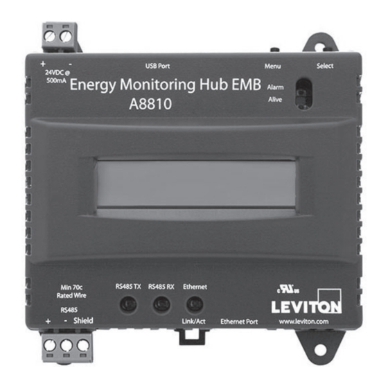
Modbus FAQ at www.leviton.com Some Modbus devices do not use the same label notation as the EMB Hub . Rather than +, -, S, Emon uses Low, High, and Gnd. To attach an Emon meter, use + to high, - to low, and shield to Gnd. - Page 8 4 INSTALLATION Power up and diagnostics: A power supply is not provided with the EMB Hub, therefore it is up to the installer to provide the required 24VDC. After the power is applied, the green “Alive” light in the upper...
- Page 9 4.4.5 The EMB Hub completes a background scan for new Modbus devices every 2-5 minutes. Increasing the RS485 Modbus timeout may increase the time required to detect new devices. If the Modbus devices are connected after the server is booted up, the devices may not appear on the screen for several minutes.
-
Page 10: Configuration
• Dynamic Host Configuration Protocol (DHCP) address this process assigns an IP address dynamically to the EMB Hub when it is connected to the network from a host DHCP server; or • Direct connection between the EMB Hub and a single temporary computer such as a laptop. (primary... - Page 11 Hub must be rebooted to take effect. Press ‘select’ to allow the EMB Hub to reboot. Once the EMB Hub has rebooted, the new IP address will be displayed on the console. If DHCP addressing was specified, the server assigned address will be displayed.
- Page 12 The remainder of this section will assume the installer has brought a laptop to the site, and will connect the laptop to the building LAN, or directly to the EMB Hub. Attach the laptop to the EMB Hub or LAN as shown.
- Page 13 Note: If you have multiple ethernet cards, you may have multiple lines labeled “TCP/IP ----> ethernet card”. Locate the ethernet card that corresponds to the physical connection to the EMB Hub and then select the TCP/IP option that is linked with that ethernet card.
-
Page 14: Emb Hub Administration Overview
6 EMB HUB ADMINISTRATION OVERVIEW The EMB Hub should now be available on the local area network for you to access using a web browser. Use your web browser to connect to the EMB Hub by entering: http://192.168.40.50/setup/ Where 192.168.40.50 is the IP address displayed on the on the EMB Hub LCD display. - Page 15 Select the Modbus/Setup menu option. Specify the Modbus Loop Name. This will become the name of the EMB Hub. This is the name that will appear on the BMO website service (if subscribed). Specify the data logging period. The default is 15 minutes.
-
Page 16: Security
The EMB Hub has three levels of security. These are “operator”, “user” and “admin”. When using a browser to access the EMB Hub , basic http authentication is used to prompt your browser for a username and password. The admin account uses “admin” as the default password. To change the password, select the Accounts menu from the left side tree display. -
Page 17: Modbus
Click on the Modbus address number for any of the devices for specific device details Note: not all Modbus devices have built in driver support in the EMB Hub. If a device appears in the list with “Unknown” in the status column, you may need to upgrade the firmware on the EMB Hub to access the device. - Page 18 To best measure the true RTT, set the ModbusSetup/RS485 timeout to the maximum period and allow the EMB Hub to run for 5 or 10 minutes. Next, review the RTT values seen in the device list page and make note of the longest RTT time shown for any device. Last, configure the ModbusSet up/RS485 timeout to the option that is the next largest than the longest time seen for any device.
- Page 19 8 MODBUS 8.3 Device Details The device detail page will show a list of all the meter data points, alarm settings and console options. The data point names for most devices are automatically entered. Some devices such as the A8332-8F2D I/O module have generic inputs, and will be labeled as “Input #1”. At the top of the page, the status of the device is shown.
- Page 20 Alarm, or above the High Alarm levels at the time a log entry is taken, the point will be considered in an alarm state. Console: Checking this checkbox will cause the EMB Hub to display this data point on the LCD console. Multiple data points are rotated about every 10 seconds. The values on the LCD console are updated when the next log interval occurs.
- Page 21 Device Type: This menu will allow the selection of any built in driver or any Modbus Framework template that is available on the EMB Hub. It is important to select the driver or template that matches the Modbus device.
- Page 22 The Modbus setup page provides several options related to the Modbus RS485 serial port. EMB Hub Name: This is the name of the EMB Hub. This name will be present on all log file descriptors when uploaded to a central database website such as BMO. It is helpful to name th e EMB Hub based on the physical location of the system, or building.
- Page 23 115200. The default is 9600, most Modbus devices communicate at this speed as well. Multiple baud rates may be selected in this menu. If multiple rates are selected, the EMB Hub will automatically detect the baud rate of each Modbus device from the chosen options. Once the baud rate has been detected for a specific Modbus device address, and will continue to communicate with that specific device address at the detected...
- Page 24 The trap includes information about the EMB Hub system data point, and alarm state. A full MIB is located on the EMB Hub , click the MIB link to the right of this option.
-
Page 25: Wireless
9.2 ModHopper Map The EMB Hub has additional diagnostic features th at assist with ModHopper deployments. The most useful is the ModHopper route map. Select the ModHoppers menu from the Wireless section in the EMB Hub menu tree as shown below. -
Page 26: Networking
DNS1, DNS2: These are the primary and secondary DNS servers. If you are using a dialout connection, these must be set to the DNS server provided by your dialup isp. If you only use the EMB Hub on a crossover cable and /or dialin mode, you should leave these blank. - Page 27 EMB Hub. NOTE: one common mistake is configuring the Laptop IP to the same address as the IP address of the EMB Hub. In order for the laptop and EMB Hub to communicate, the IP addresses should not be identical. (See the basic network config for suggested IP addresses.) •...
-
Page 28: System Options
If you are operating your own database system to store log data from the EMB Hub, it is best to store the data in UTC time in the database as well, and only convert it to local... - Page 29 If you store data in local time, you will have the following issues. Local time is relative. Is Local the time where the EMB Hub exists, or local to where the data is stored? If local to the EMB Hub , you must shift each EMB Hub data set depending on its location.
- Page 30 “Install” button. Click the install button and the EMB Hub will install the firmware update and reboot itself to make the changes take effect. Do not power down the EMB Hub during any step of the EMB Hub firmware update process. Doing so may corrupt the system and render the EMB Hub unusable.
-
Page 31: Diagnostics
Traceroute: Send an echo request to the target address and attempt to locate every router in between the EMB Hub and that address. Nslookup: convert the DNS name to an IP address, useful for testing the functionality of the DNS server configured in the Network/Setup webpage. -
Page 32: Lcd Console
The TCP/IP sub menu will allow you to configure the ethernet settings for the EMB Hub. To edit the IP settings, use the menu button to change options, and press the select button to edit the option. Once selected, you will see the curent value displayed and a blinking square cursor on the first character. - Page 33 Shutdown: This option will stop the data logging processes and secure the flash memory. When secured, the console will state that the power may be disconnected. It is important to shut down the EMB Hub cleanly prior to disconnecting the power from the device.
-
Page 34: Log File Data
Log File Format Once you have downloaded the data from the EMB Hub , you will need to process it. The file is an ASCII text file with comma delimited data. One line is recorded for each log cycle. The file will look something like the following example from a 4A4P-M I/O Module. - Page 35 This is because the 9600 baud speed of the Modbus loop is not fast enough to log all Modbus devices in less than 1 second. If a device does not respond during a log cycle, the EMB Hub will attempt to query the device several more times.
- Page 36 For data exported from the BMO website, the columns that are invalid (NULL) are reported as blank fields. This makes it easier to import into MS Excel as blank cells. With the current firmware, the EMB Hub will report blank fileds rather than “NULL” to make direct import of data from the EMB Hub easier, as well as reduce the file size.
- Page 37 files to your server, you must manually delete them. To delete log files, refer to the FTP method of downloading log files. One step detailed in the FTP section is how to delete a log file from the EMB Hub.
- Page 38 • Time to wait before retry: In the event of a failure, the EMB Hub can be configured to wait for a specified period of time before attempting another connection. This option specifies how long to wait before retrying.
-
Page 39: Retrieving Data From The Emb Hub
HTTP Direct from the EMB Hub The EMB Hub has the ability to export log file data to a web browser directly from the setup web pages. To use this feature, access the EMB Hub setup menu with your web browser. Select the “Log File Export”... - Page 40 files from its flash memory once the EMB Hub has confirmed that the file was received by the database server. If you are using the EMB Hub with a standalone mode, you can use FTP to delete log files from the flash memory.
-
Page 41: Mechanical Drawings
The EMB Hub uses a plastic enclosure that is approximately 4 in x 4.25 in x 2 in deep. The EMB Hub has 4 mounting holes for use with a #6 screw. The drawing above shows the relative position of the mounting holes. -
Page 42: Warranty And Contact Infromation
LIMITED 2 YEAR WARRANTY AND EXCLUSIONS Leviton warrants to the original consumer purchaser and not for the benefit of anyone else that this product at the time of its sale by Leviton is free of defects in materials and workmanship under normal and proper use for two years from the purchase date. - Page 44 DI-005-A8810-00A...
Need help?
Do you have a question about the EMB Hub and is the answer not in the manual?
Questions and answers