
Related Manuals for Pacific Scientific Danaher Motion P70360


Summary of Contents for Pacific Scientific Danaher Motion P70360
- Page 1 (217) 352-9330 | Click HERE Find the Kollmorgen / Pacific Scientific P70360-SDN at our website:...
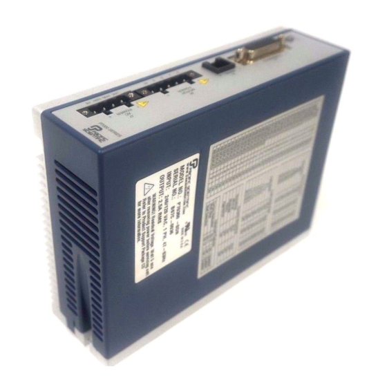
- Page 2 P70360 (AC) High Performance Micro-stepping Drive Quick Start Guide Part # M-SD-7AC-07 Initial Release NOTE: This is only a Quick Start Guide. Visit our website at http://www.danahermotion.com/documents/ or browse the Product Support Package CD-ROM shipped with your product to find the complete Installation Reference.
- Page 3 Copyright Information © Copyright 2006 Danaher Motion – All rights reserved. Printed in the United States of America Notice Not for use or disclosure outside of Danaher Motion except under written agreement. All rights are reserved. No part of this book shall be reproduced, stored in retrieval form, or transmitted by any means, electronic, mechanical, photocopying, recording, or otherwise without the written permission from the publisher.
- Page 4 120 V Wiring Connection for a 320 VDC bus using 120 VAC. P7000 Cable Part Number: P7S2-232-9D MOTOR Typical Pacific EARTH GND Scientific Stepper Wire Color Code LINE A- Orange 120N A+ Black EARTH GND B- Yellow B+ Red PE Green/Yellow Stripe M-SD-7AC-07 Initial Release Artisan Technology Group - Quality Instrumentation ...
- Page 5 240 V Wiring Connection for a 320 VDC bus using 240 VAC. P7000 Cable Part Number: P7S2-232-9D MOTOR Typical Pacific EARTH GND Scientific Stepper Wire Color Code LINE 240N A- Orange EARTH GND A+ Black B- Yellow B+ Red CAUTION PE Green/Yellow Stripe Connecting 240 VAC to pin 3 or AC power connector will damage the drive!
-
Page 6: Setup Wizard
Install P7000Tools Install P7000Tools either from the Product Support Package CD-ROM or download it from the website (www.danahermotion.com). When you install P7000Tools, the Installation Wizard will check to see if you have a previous version of P7000Tools on your system. If found, it will uninstall it. - Page 7 Go to the Advanced Setup screen. Enable the "Anti-Resonance" function. Initial Release M-SD-7AC-07 Artisan Technology Group - Quality Instrumentation ... Guaranteed | (888) 88-SOURCE | www.artisantg...
- Page 8 Motion Toolbar Go to the Motion Toolbar. Jogs the motor in the negative direction at the Jog Motor Negative selected velocity Selects the active jog velocity for the Jog Jog Velocity Toggle arrow buttons (L designates Low Speed, H designates High speed) Jogs the motor in the positive direction at the Jog Motor Positive selected velocity...
-
Page 9: Status Display
Status Display There are 7 faults that may occur with the P7000 drive. The fault output latches when they occur. Determine the type of fault by viewing the front panel or through the serial port. The front panel LED turns red and blinks according to the table below. - Page 10 LED Color Blinks Description Cause Solution Amber Solid EOT± input An EOT Move system latched (End of in the opposite Travel) input direction until is latched. the active EOT input transitions from asserted to de-asserted. M-SD-7AC-07 Initial Release Artisan Technology Group - Quality Instrumentation ... Guaranteed | (888) 88-SOURCE | www.artisantg...
- Page 11 LED Color Blinks Description Cause Solution Solid FLASH A FLASH Without memory memory attempting to fault checksum connect to the validation drive, has failed download the indicating most current corruption of firmware file the operating from the system. P7000Tools menu option This Drive->Update typically...
- Page 12 LED Color Blinks Description Cause Solution Stall Fault Reduce move Encoderless profile Stall acceleration, Detection velocity, feature has deceleration or detected that load inertia. the motor Power cycle or has slipped reset drive via or stalled. Fault Reset input or P7000Tools.
- Page 13 LED Color Blinks Description Cause Solution Over-voltage Reduce Fault regenerative deceleration, event has load inertia, or occurred reduce which forced deceleration the bus duty cycle to voltage allow enough above 440 time for the VDC. power dump circuit to Incoming recover.
- Page 14 LED Color Blinks Description Cause Solution Drive Over- Reduce temp Fault temperature ambient of the temperature or heatsink has system duty exceeded cycle. 70° C. Power cycle or reset drive via Fault Reset input or P7000Tools. System Fault An error Power cycle or occurred reset drive via...
- Page 15 LED Color Blinks Description Cause Solution Under- Attempting Power cycle or voltage Fault to operate reset drive via the unit at a Fault Reset bus voltage input or below 10 P7000Tools. VDC. Incoming AC line voltage too low. EEPROM User non- Restore default Checksum volatile...
- Page 16 LED Color Blinks Description Cause Solution Alternating Multi Processor Internal Contact Red & Fault system error. technical Amber support. The blinking continues until the drive is reset by one of the following methods: Power Cycle GUI Control Fault Reset (Configurable General Purpose Input) M-SD-7AC-07 Initial Release Artisan Technology Group - Quality Instrumentation ...
-
Page 17: Sales And Service
Sales and Service Danaher Motion is committed to quality customer service. Our products are available world-wide through an extensive authorized distributor network. To serve in the most effective way, please contact your local sales representative for assistance. If you are unaware of your local sales representative, please contact us.
Need help?
Do you have a question about the Danaher Motion P70360 and is the answer not in the manual?
Questions and answers