
Related Manuals for Zipp Manufacturing Illusion


Summary of Contents for Zipp Manufacturing Illusion
- Page 1 Z I P P M A N U F A C T U R I N G A Zippkits R/C Boat Building Instructions 2009 Zipp Manufacturing 750 Ball Road • Frankfort, New York 13340 www.zippkits.com Toll Free (866) 922-ZIPP...
-
Page 2: Table Of Contents
T able of Contents Introduction Fuel Tank S E C T I O N T H E F R A M E Supplies needed to build S E C T I O N P A I N T Equipment needed to run Hull prep Building Surface Sanding and Filling... -
Page 3: Introduction
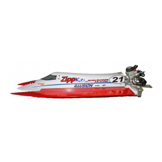
I L L U S I O N Introduction Thank you for purchasing this kit. We are sure that it will provide you with many hours of enjoyment. Please take the time to read this entire manual before building this boat. - Page 4 This boat was created as a race boat, designed for the Gasoline outboard tunnel class. The boat is currently legal in all Gas Tunnel classes. “G” Drive, and a The Illusion was designed specifically for the Lawless ® Zenoah Gasoline engine.
-
Page 5: Supplies Needed To Build
I L L U S I O N Tools and supplies needed to build: Small wood plane (mini plane) Sanding blocks with 80 and 220 grit paper Drill with bits Square 12x48 FLAT plywood or bench (the thicker the better) ... -
Page 6: Equipment Needed To Run
I L L U S I O N Additional items needed to complete: Zenoah Gasoline engine Lawless “G” Drive outboard drive unit Tuned pipe or canister muffler (check the rules) 2 channel surface radio with 1 standard and 2 heavy duty servos (300 in/oz minimum each) ... -
Page 7: Parts Identification
I L L U S I O N The Build We are ready to start the build! Remember- The boat is being built upside down. Any reference to the top or bottom refers to the boat’s top or bottom. If you are going to attach something to the top, it would be closest to the bench. - Page 8 I L L U S I O N Take the time to mark all the parts, as there are a few parts that are similar, but not the same.
- Page 9 I L L U S I O N We like the Great Planes 11 inch bar sanders Your life will be much easier with one of these Acid brush trimmed for fast epoxy application Use good quality epoxy and finishing resin...
-
Page 10: Building Jig
I L L U S I O N Let’s get started. Attach the jig board to your FLAT bench (or 12x48 ply) with screws, nails, clamps or whatever you need, to make sure it’s attached to the surface. Make sure the “F” is so that you can read it. Remove bulkheads R, 4, 6 and the (2) sponson sides. -
Page 11: Fuselage Sides
I L L U S I O N When done, check to make sure everything is flat, flush and square, and then reglue all joints with thin Fuselage sides Remove and sand the two fuselage sides, and carefully slip them up into the bulkheads from the bottom. -
Page 12: Chines
I L L U S I O N Glue in the front and rear radio box mounts. These go into slots in the sides as they are assembled. The radio box mount with the blind nuts goes in the rear, with the blind nuts facing up. Slide one side (at the front) out of place and insert the radio box mounts. - Page 13 I L L U S I O N Be sure that the side chine is not hanging down below bulkhead 6 also. Use thin CA and accelerator to glue the side chine in place. Repeat on the other side. Side chine flush with the bottom of the sponson side.
-
Page 14: Side Sheeting
I L L U S I O N Sponson side sheeting Plane and sand the side of the framework so that Bottom chine detail. the side sheeting will sit flat on the framework. Time to get intimate with your wood plane. If you don’t have one, stop here. -
Page 15: Bottom Sheeting
I L L U S I O N Start clamping, adjusting the sheeting for equal overlap on the top and bottom. Clamp thoroughly, but be careful not to distort the chines. Using a new mixing container and applicator, do the other side. -
Page 16: Radio Box
I L L U S I O N Let’s build the radio box while the glue cures on the hull. Radio Box Remove all of the radio box parts: Two long sides, two short sides, the top and bottom, as well as the 1/8 ply top. - Page 17 I L L U S I O N Draw a line 2 inches from the end of the radio box. Make sure it’s the end without mounting holes. Using medium CA, glue the radio box spacer to the bottom of the radio box, along the line you drew. Radio box spacer installed 2 inches from front.
-
Page 18: Transom Assembly
I L L U S I O N Back to the boat: Make sure that it has been at least 3 hours since you glued the bottom sheeting to the hull. Hull trimmed and sanded. Trim the excess bottom sheeting flush. You can use your small plane to get close. - Page 19 I L L U S I O N When the transom assembly is cured, install the side extensions with medium CA. Do not use accelerator. Repeat on other side. Side extensions in place. When the transom assembly is cured, install the transom braces with medium CA.
-
Page 20: Sealing Interior
I L L U S I O N Sealing Interior Lots of strength here… Now we need to seal the inside. It is vital that all exposed wood be sealed. Mix up about 4 ounces of epoxy finishing resin or West Systems epoxy. -
Page 21: Deck Sheeting
I L L U S I O N After the hull sealer has had a chance to cure, let’s get the hull ready for the top sheeting. Top Deck Sheeting Epoxy/filler fillets inside center section Trim the building tabs, and sand the bulkheads and framework flat. - Page 22 I L L U S I O N slightly pull the sides out to the deck. Continue adding weight until the entire deck is in contact all the way around. Check the transom from behind. Check the nose as well. Allow to cure overnight.
- Page 23 I L L U S I O N Trim the nose back, so that it is not so sharp. If it were left sharp, it could hurt… Trim nose to a blunt point. Sand the nose to a nice round shape. At this time, you should look over the entire hull, and sand any glue bumps or uneven seams, etc.
-
Page 24: Cowling
I L L U S I O N Glue them so that they are flush (or a little above) with the top, and a little short on the bottom. Use medium CA. Flush, or slightly above the top sheeting. Sand the tops flush with the center section top, and sand the tunnel top sheeting to meet them. - Page 25 I L L U S I O N Glue this to the top of the cowl bottom, flush with the rear. Mount and dowel glued in place. Sand the edges of the ¼ inch dowel, and glue it into the hole in the mount. Make it flush with the inside. Dowel serves as front mount for cowling.
- Page 26 I L L U S I O N When you are happy with the fit, glue the cowl bottom in place with 30 minute epoxy. Also coat the top of the wood with epoxy, as it will be difficult to seal once it is in place. Cowl bottom sealed with epoxy prior to being glued to the cowling.
-
Page 27: Cowl Mounting
I L L U S I O N Using a Dremel cutoff wheel or a razor saw, carefully make the ¾ inch high cut against the front mount. Then make the long cut. You can use a utility knife if you lay the cowling on the edge of your bench. You can also use a razor saw or Dremel. - Page 28 I L L U S I O N Use a black marker to “paint” the end of the dowel. Use plenty of ink. Slide the cowling into place, making sure the bottom edge of the cowling is resting on the top deck.
- Page 29 I L L U S I O N Cowling in place. With the cowling fully seated, mark and trim off the excess in the rear. Sand the edge so that it is even. Rear of cowling marked for trimming. Cowling trimmed. Make a mark 2 inches forward of the rear of the cowling, and ¾...
- Page 30 I L L U S I O N Make sure the cowling is still fully seated, and drill a hole with a #7 (.201) bit. Do this on both sides, being careful not to disturb the cowling position. Remove the cowling and drill the holes out to ¼ in the cowling only.
-
Page 31: Servo Installation
I L L U S I O N Hold the throttle servo at the end of the mount, mark the hole locations in the ply. Be sure to leave a 1/16 gap between the servo case and the mount. Drill on the marks with a 1/16 bit. Repeat for the other side. - Page 32 I L L U S I O N Glue one of the large servo mounts into the box, aligning the top of the mount to your line. You can use medium CA for this. First servo rail installed. Extend your line 2-11/16 from the edge of the first mount, and glue in the other mount.
- Page 33 I L L U S I O N Glue in the throttle servo, aligning it to your line and centering it in the box. Throttle servo in place. Attach the rudder servos to their mounts as follows: Assemble the servo arms and tie bar for a 3-1/2 inch center to center length for the pushrods.
-
Page 34: Engine Mounting
I L L U S I O N Seal the inside and outside of the radio box with finishing resin or West Systems. Use a metal acid brush, bent over, to seal the underside of the top. Be careful not to get any excess resin in the “lip” where the lid seats, as this would interfere with the seal of the lid. - Page 35 I L L U S I O N Align the top of the pattern with the top of the transom, and center it side to side. Drilling pattern attached to transom. Use a punch to mark the holes. Remove the pattern and drill the holes with a 3/16 Holes center punched.
-
Page 36: Setup Board
I L L U S I O N Bolt the bracket to the transom. Note that we put the nut plate outside the transom, and used shorter bolts. It is much easier to adjust from inside the transom. At this time, you should make a setup board from a piece of flat ¾... - Page 37 I L L U S I O N Radio Box Installation The radio box installs by sliding under the front mount, and with the two 6-32 screws and washers in the rear. If you have trouble sliding the front mount in place, you can use a file to clean the slot.
-
Page 38: Fuel Tank
I L L U S I O N These braces are made to mount against the first bulkhead, and support a ¼ inch pushrod. Pushrod brace detail. Fuel Tank We like using an IV bag (500mL) for a gas bag. Very simple to use, water proof and rugged. -
Page 39: Hull Prep
I L L U S I O N Finishing Sand the entire hull with 80. Fill any dings, dents, craters, valleys or chips with wood filler. When dry, sand again with 80. Check to make sure that all imperfections are filled. If not, fill and sand again. -
Page 40: Primer And Paint
I L L U S I O N Once the hull is dry, wipe it down with alcohol. Use a tack cloth lightly to remove any dust. Spray a light coat of primer, inside and out. Let this flash for a few minutes, and spray a heavy coat on. Let sit overnight. -
Page 41: Setup
Make sure all your water lines are firmly attached. Use those teeny little tie wraps at each fitting. Center of Gravity The illusion should balance 24 to 28 percent from the back of the boat. That is 10-1/2 to 12 inches from the back of the... -
Page 42: Balance
I L L U S I O N To check the CG, mark the bottom of the hull at 10- 1/2 and 12 inches. With the boat completely ready to run, except fuel, set the boat on a long dowel or skinny (1/4 inch) stick. - Page 43 It’s a good idea to have a helper write down your comments as you run the boat. After the run, you can use the included “Tunnel Tuning Tools” sheet to help you sort any problems. We hope you enjoy your Illusion Gas tunnel as much as we enjoy ours!
- Page 44 I L L U S I O N Tunnel tuning tools Drive: Depth- Lower to loosen the boat, higher to wet the boat. Imagine that the prop wants to always ride at the same depth in the water. If you lower the prop, you are lifting the boat out of the water.
- Page 45 I L L U S I O N Troubleshooting Boat bounces in the straights- Drive angle positive Prop too deep Speed too slow Boat blows over at high speed- CG too far back Drive angle positive Boat “plows”- CG too far forward Drive angle too negative Debris caught under boat Boat is very “light”...
Need help?
Do you have a question about the Illusion and is the answer not in the manual?
Questions and answers