Table of Contents

Related Manuals for Roland V-Drums VH-14D


Summary of Contents for Roland V-Drums VH-14D
- Page 1 Owner’s Manual Before using this unit, carefully read “USING THE UNIT SAFELY” (p. 2) and “IMPORTANT NOTES” (p. 2). After reading, keep the document(s) where it will be available for immediate reference. © 2021 Roland Corporation...
- Page 2 Do not place in a location that is unstable Do not disassemble or modify by yourself For a list of Roland service centers and to get fingers, toes, etc., pinched. official Roland dealers, refer to the Roland...
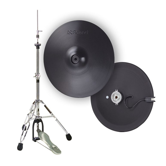
- Page 3 Introduction Check the Included Items VH-14D Components After opening the package, check that all of the included items are Outside of top cymbal present. If anything is missing, contact your dealer. * When you open the package, small spots appearing to be moisture might be visible on the surface of the product.
- Page 4 Installing the Cymbals onto the Hi-Hat Stand (1) Assembling the Bottom Cymbal The link jacks A/B should be on the left and right sides from the player’s perspective at this time. Remove the clutch included with the hi-hat stand from the cymbal rod. * The clutch included with the hi-hat stand will not be used.
- Page 5 At this point, position the “Roland” logo on the farther side, as strongly pulling the clamp downward, secure it with viewed from the performer.
- Page 6 Installing the Cymbals onto the Hi-Hat Stand (3) Connecting to a Sound Module (4) Adjusting the Sound Module * Use a Roland drum sound module that is compatible with the When using the VH-14D, you will need to make the settings for the VH-14D.
- Page 7 Installing the Cymbals onto the Hi-Hat Stand When Not Playing (5) Adjusting the Hi-Hat When you’re not playing, secure the top cymbal and bottom cymbal Adjust the gap between the top cymbal and bottom so that they are separated by at least 10 mm of space. Malfunction cymbal to a clearance of approximately 10 mm, then may occur if they are not separated.
- Page 8 Trigger (Bow/Edge) DIGITAL TRIGGER OUT jack Diameter: 6.0–7.0 mm Connectors (compatible with Roland drum sound module equipped with DIGITAL (0.236”–0.276”) TRIGGER IN port) Power Supply Supplied from DIGITAL TRIGGER IN port (DC 5 V) Current Draw 90 mA x 356...
Need help?
Do you have a question about the V-Drums VH-14D and is the answer not in the manual?
Questions and answers