
Related Manuals for Eaton 9479-ETG-CSL


Summary of Contents for Eaton 9479-ETG-CSL
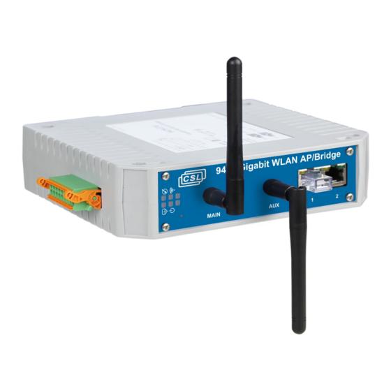
- Page 1 Instruction manual March 2021 MTL Industrial Network Solutions INM 9479-ET(G)-CSL Rev 1 9479-ET(G)-CSL CSL Intrinsically Safe Gigabit Ethernet WLAN AP / Bridge...
- Page 2 DECLARATION OF CONFORMITY A printed version of the Declaration of Conformity has been provided separately within the original shipment of goods. However, you can find a copy of the latest version at - http://www.mtl-inst.com/certificates INM 9479-ET(G)-CSL Rev 1...
-
Page 3: Table Of Contents
CONTENTS FEATURE . . . . . . . . . . . . . . . . . . . . . . . . . . . . . . . . . . . . . . . . . . . . . . . . . . . . . . . . . . . . . . . . . . . . . . . . . . 1 DESCRIPTION . - Page 4 No changes to any of the components that might impair their explosion protection are permitted. If any information provided here is not clear: Contact Eaton’s MTL product line or an authorised distributor or sales office. NOTE Improper installation and operation of the enclosure can result in the invalidation of the guarantee .
-
Page 5: Feature
FEATURE • Intrinsically Safe ATEX / IECEx Certification • Dual Band 2.4GHz / 5GHz WLAN Support • Dual Antenna 802.11n MIMO 2T2R • Access Point (AP) Mode or Client/Bridge Mode • Dual Port Switch 10/100/1000MB LAN (daisy-chain capability) • Versions: 2x Gigabit LAN Ports (-ETG), or 2x 10/100 LAN/PoEx* Ports (-ET) •... -
Page 6: Description
DESCRIPTION The 9479-ET(G)-CSL is an Intrinsically Safe (IS) WLAN AP/Bridge Module suitable for Zone 1 / Zone 21 mounting, (Zone 0 / Zone 20 with a suitable Ex ia Power Supply). It may be configured as either an AP or Client/Bridge. Also supporting either 2.4GHz or 5GHz operation further extends its range of applications. -
Page 7: Connections
CONNECTIONS 3 .1 DATA & POWER TERMINALS Power + External IP Rated LEDs (CON1) Function Function Power In +12V# Power In 0V# LAN1 PoEx +12V# LAN1 PoEx 0V# LAN2 PoEx +12V# LAN2 PoEx 0V# LAN1 LED LAN2 LED WLAN LED #Connect LAN1 OR LAN2 PoEx terminals to Power In terminals to use this function External IP66 rated LEDs wire down to 0V Power Ui = 15.4V... -
Page 8: Ordering Information
ORDERING INFORMATION Part Number Description Comments 9479-ETG-CSL Gigabit WLAN AP / Bridge Standard 9479-ET-CSL WLAN AP / Bridge (10/100 PoEx) Special Order (Subject to MOQ) Note: 2x Antenna required (not included) these need to be ordered separately Accessories Part Number... -
Page 9: Installation
INSTALLATION WARNING ! See Special Conditions of Safe Use in the folllowing section regarding ATEX & IECEx Certification Information before installation The 12V supply to the module connects via screw terminals 1 + 2 as shown above. If the unit is being powered using Power over Ethernet (PoEx), it is required that you connect the relevant PoEx power terminals (Con1) to the main power supply pins (Con1), see connections section. -
Page 10: Atex & Iecex Certification Information
ATEX & IECEx CERTIFICATION INFORMATION The following information is in accordance with the Essential Health and Safety Requirements (Annex II) of the EU Directive 2014/34/EU [the ATEX Directive- safety of apparatus] and is provided for those locations where the ATEX Directive is applicable. General a) This equipment must only be installed, operated and maintained by competent personnel. - Page 11 8 .6 The equipment shall be mounted on an earthed metal bracket or housing. Marking Each device is marked in accordance with the Directive and CE marked with the Notified Body Identification Number. 9479-ETG-CSL Product Label INM 9479-ET(G)-CSL Rev 1...
-
Page 12: Specification
Specification Power supplies 12VDC IS Power Supply Input PoEx (Power over IS Ethernet) Typically 12V @ 300mA (Inrush < 400mA) Ui =15.4V 9492-PS-PLUS recommended Ethernet Intrinsically Safe 10/100/1000Base-T Connector RJ45 (x2) Cable Length Up to 100m Cat5e WLAN TX Output – 802 .11n 2.4GHz: 18 to 20.5 dBm 5GHz: 15 to 18 dBm (per antenna output in 2T/2R mode) -
Page 13: Approvals
APPROVALS Location of Unit Zone 1, IIB T4 hazardous area (9479-ETG) Zone 1, IIC T4 hazardous area (9479-ET) Certification Code Ex ia IIB T4 Ga (9479-ETG) Ex ia IIC T4 Ga (9479-ET) Ex ia [ia Da] IIIC T135°C Db (non-mining) Ex ia I Ma (M1 mining) Ta = -40ºC to +70ºC Certificate numbers... -
Page 14: Network Setup
Network Setup To begin configuring the unit, the Default IP Address is 192 .168 .1 .253 This page displays the current network configuration. Click the ADD NETWORK button to create a new IP network. Click the REMOVE button under the ‘action’ heading to remove the selected network. Click the EDIT button under the ‘action’... - Page 15 General Setup: Enable Interface: Tick this box to enable the selected network interface. Network Description: This entry is to provide an identification to your network Protocol: Choose DHCP if you have a DHCP server in the network and you want to assign an IP address to the AP .
-
Page 16: Wi_Fi Setup
Network Persistence: When this option is enabled, the IP setting (routes, gateway, virtual interfaces) remains persistent when the physical interface loses its connection. Default value is enabled for static IP , and disabled for DHCP . Wi-Fi Setup This page allows the user to configure the wireless network settings, by default the radio will be disabled and you will need to turn in on. - Page 17 Device Configuration: General Setup: This selection gathers all the settings that are common to each SSID you may create on this radio. Enable Device: If this box is checked, the radio card is enabled and is able to communicate. Uncheck it to disable the radio. 802 .11 Mode: The 802.11g+n mode operates in the 2.4GHz band and is compatible with 802.11g and 802.11n devices.
- Page 18 Other Roles: The other roles, (mesh portal, ad-hoc) support only one channel, this parameter is not available and you must select a channel in the dropdown box. Channel: According the selected 802.11 mode and the regulation rules of the selected country, a list of channels is available for selection.
- Page 19 Short Retry: This is the number of retries for a physical data frame. Long Retry: This is the number of retries for a physical data frame sent with the RTS/ CTS protocol Aggregate Retry: This option configures the number of retries for a frame aggregated into an A-MPDU.
-
Page 20: Dhcp Server
DHCP Server General Setup: Ignore interface: If checked, the DHCP server will be disabled on the selected interface. DHCP pool first address (if enabled): First IP Address of the DHCP pool. This is interpreted as an offset relative to network address. DHCP pool size (if enabled): Maximum number of leased addresses. - Page 21 Advanced Settings Dynamic DHCP: If unchecked, only static leases will be authorized. Force: By default, the DHCP service doesn’t start if it detects the presence of another DHCP server on the network. If this option is checked, the DHCP server wont check for another server before start.
-
Page 22: System Status
System Status 15 .1 Device information The Device Information page allows a quick overview of the unit’s useful information and the currently installed firmware information. 15 .2 Network Interfaces This Page shows a summary of the currently configured network interfaces and displays the transmitted and received packets. - Page 23 Pressing the Graph button will present a history graph of the selected interface, the following information will be available; Tracing Bytes graph: Displays the number of bytes of transmission and reception on the interface Packets graph: Displays the number of processed, dropped and error packets of transmission and reception on the interface Broadcast/Multicast graph: Displays the number of Broadcast/ Multicast Packets on the interface...
-
Page 24: Routes
Routes This Page shows all of the active IPV4 Routes on the unit. This page displays all the available information about the running instance of the PIM multicast router. Network interface: Interface: The Network number referred to in the ingress/egress columns. Local Address: Unicast IP address assigned to the network in the setup/Network Page Subnet: The subnet that this interface connects to and the number of subnet bits. -
Page 25: Http/Https
Multicast routes section: Route type: (*,G) for any source to group, (S,G) for specific source to group. Multicast source: Source requested by the receiver: any or a specific IP Address. Multicast group: The group concerned by the route entry. In Use: This entry is actively used to forward date. Rendezvous Point: The IP Address that was computed for the group. -
Page 26: Firmware
Firmware This page allows you to upgrade the firmware in the unit. All previous configuration changes will be left unchanged. Password These Pages allow you to change the Password on both the Root and the user accounts. On initial power up, both passwords are set empty, this will allow you to enter the unit and configure the unit, as you require . -
Page 27: System
System Host Name: This is a user definable Host Name for the device. System Time: This is the current system time. Local time is lost on a reboot, use an NTP server if required Time Zone: This allows you to set the time zone you are in. Device Location: This is a user definable device location field. -
Page 28: System Log
System Log This panel allows for the visualization of the units logs. Config Log: This log displays a summary of the units configuration Kernal Log: This log displays messages from the Linux kernel only. System Log: This log displays messages from both the kernel and from the running services. - Page 29 This is the log settings page, it allows you to configure the system logs. Systems Log Out Level: This sets the minimum level of a message to allow its insertion in the system log. External System Log server and port: Optional remote log server configuration. IP Address and UDP port where the log messages will be sent using the syslog protocol.
-
Page 30: Network Utilities
Network Utilities This panel provides two standard UNIX tools: ping and traceroute. Place the argument in the text field above the corresponding button and then click the button. The results will be displayed in a frame below. Save Config / Reset The Save and restore configuration section allows you to backup the units current settings to a file. - Page 31 This page is left intentionally blank INM 9479-ET(G)-CSL Rev 1...
- Page 32 AUSTRALIA NORWAY Eaton Electrical (Australia) Pty Ltd, Norex AS 10 Kent Road, Mascot, New South Wales, 2020, Australia Fekjan 7c, Postboks 147 , N-1378 Nesbru, Norway Tel: +61 1300 308 374 Fax: +61 1300 308 463 E-mail: mtlsalesanz@eaton.com Tel: +47 66 77 43 80 Fax: +47 66 84 55 33 E-mail: info@norex.no...
Need help?
Do you have a question about the 9479-ETG-CSL and is the answer not in the manual?
Questions and answers