
Related Manuals for Charmhigh CHM-T48VB


Summary of Contents for Charmhigh CHM-T48VB
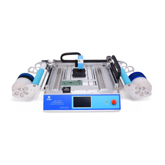
- Page 1 2016 Charmhigh Automatic Chip Mounter ( CHM-T48VB) Operating Manual CHARMHIGH TECHOLOGY LIMITED 长沙常衡机电设备有限公司 http://www.charmhigh.net Technology Versus Future-V1.0-2016 2016-06-01...
-
Page 2: Table Of Contents
By Altium Designer ..................37 12.1.2. By Protel ......................39 12.2......................42 ONVERT 12.2.1. Material Stack ....................44 12.2.2. Component....................44 12.2.3. Batch ......................45 LOG ..........................47 SYSTEM LOG ......................48 QUICK START ......................48 Charmhigh-V1.0-2016 | All Rights Reserved... - Page 3 MAINTENANCE ......................53 WARRANTY ......................... 54 Charmhigh-V1.0-2016 | All Rights Reserved...
-
Page 4: Revision History
1. Revision History Date Description Version 2016-06-01 Create document V1.0 Charmhigh-V1.0-2016 | All Rights Reserved... -
Page 5: Install The Machine
Check if the machine is in good condition, check the list of products, if you have any questions please contact us; Please read this manual carefully before use SMT machine; There's any problem in use, welcome to contact. Charmhigh-V1.0-2016 | All Rights Reserved... -
Page 6: Product List
3. Product List Parts Quantity Remarks SMT machine nozzles 503,504,505,506 USB flash disk power cord Charmhigh-V1.0-2016 | All Rights Reserved... -
Page 7: Hardware Requirements And Compatible Software
4. Hardware Requirements and Compatible Software 4.1. Hardware Requirements All equipment are built-in, don't need other external devices. 4.2. Compatible Software Compatible with Protel99se, Altium Designer. Charmhigh-V1.0-2016 | All Rights Reserved... -
Page 8: Notices
(11) Don't let the pull needle in the stretched state for a long time, or it could be damaged; (12) Don't put machine direct exposure to sunlight or bright light, otherwise may cause the machine precision reduce or damage to the machine. Charmhigh-V1.0-2016 | All Rights Reserved... -
Page 9: Technical Parameters
6. Technical Parameters model CHM-T48VB PCB area 10mm×10mm~355mm×355mm X,Y axis stroke 510×460mm Z axis stroke 15mm number of nozzle material stack number ordinary material stack 58, IC material stack up to 14 visual support dual cameras Closed-loop servo high voltage drive system ( Ensure the Motor drive accuracy of operation)... -
Page 10: Mechanical Structure
(10)IC material stack: Used for placing the larger IC; (11)Touch screen: Used for manipulating and control the machine; (12)USB interface: Used for connecting the USB storage device; (13)Emergency stop switch: Emergency stop after press down, machine normal Charmhigh-V1.0-2016 | All Rights Reserved... - Page 11 (14)Power switch: Note, open this button to boot, shutdown should first close the software through the touch screen, and then close the button. Charmhigh-V1.0-2016 | All Rights Reserved...
-
Page 12: Boot The Machine
(4) Set: Used for setting various parameters that machine work required; (5) Log: Used for viewing the record information; (6) System Log: Used for viewing the log of system; (7) Files: Used for managing and convert work file. Charmhigh-V1.0-2016 | All Rights Reserved... -
Page 13: Run
(6) Back: Click left arrow button on the upper right corner of the screen to return to the previous level screen, other screen similarly. 9.1. Edit Work File The work file editing screen shown as below, can edit component, material stack, batch, IC tray and PCB calibration respectively. Charmhigh-V1.0-2016 | All Rights Reserved... -
Page 14: Component
The popup screen as shown below, the top left of the screen displays the current component‟s line number (start from 0),the arrows on both sides, used for selecting a component before or after, also can click the middle button popup keyboard to input device line number directly. Charmhigh-V1.0-2016 | All Rights Reserved... - Page 15 (10) Coord. Y: Component coordinate Y, generally do not need to modify if it is generated in work file; (11) Skip comp.: Check indicate not mount; (12) Vacuum detect: Check indicate not throw material due to vacuum insufficient, Charmhigh-V1.0-2016 | All Rights Reserved...
- Page 16 (1) Coordinate: Coordinate offset display in the upper left corner; (2) MHead\Vision: Switchover coordinate set mode among nozzle and vision, the figure below shows the screen that set coordinate by nozzle, in this mode user need to check position by eye; Charmhigh-V1.0-2016 | All Rights Reserved...
-
Page 17: Material Stack
(7) MHead n(n is MHead number): When use nozzle to positioning, click this button then specified nozzle press down, for the convenience of observation; (8) Apply: Click to apply changes. 9.1.2. Material Stack Screen show as below, in this page can manage different kinds of component‟s place position. Charmhigh-V1.0-2016 | All Rights Reserved... - Page 18 (3) Insert: Insert a new one to the position that before current selected material stack; (4) Delete: Delete selected material stack, note, all of components that use this material stack in the component list will be deleted too; (5) Edit: Edit selected material stack, screen show as below. Figure.9-7 Charmhigh-V1.0-2016 | All Rights Reserved...
- Page 19 Charmhigh-V1.0-2016 | All Rights Reserved...
-
Page 20: Batch
Figure. Figure. 9.1.3. Batch Batch is that splicing a number of same PCBs to mount together, but just need one Charmhigh-V1.0-2016 | All Rights Reserved... - Page 21 Figure. 9-10 Batch list have one record at least, click “Add skip” button to add a skip record, i.e. do not mount added PCB when machine running, click “Edit” button popup window as show below. Charmhigh-V1.0-2016 | All Rights Reserved...
- Page 22 Note, while there have only one record in batch list that indicates batch is disabled, and the data is invalid. Each record preserve a origin point of PCB while there have several records, click “Edit” to modify the coordinate or set it via location directly. Charmhigh-V1.0-2016 | All Rights Reserved...
-
Page 23: Ic Tray
Window as show below. Figure.9-13 Material stack will be added to IC tray list automatically if material stack number is from 80 to 99 in material stack list, click “Edit” to popup window as show below. Figure. 9-14 Charmhigh-V1.0-2016 | All Rights Reserved... -
Page 24: Pcb Calibration
Figure. 9-15 9.1.5. PCB Calibration In order to eliminate PCB position and angle of deviation, it is necessary to calibrate PCB before mount, screen as show below. Charmhigh-V1.0-2016 | All Rights Reserved... - Page 25 Note, if use array mode of batch, the choice of calibration point should be top left corner and bottom right corner of the whole PCB which consist of several same PCB. Window as show below, click in sequence to locate actual position of calibration points. Charmhigh-V1.0-2016 | All Rights Reserved...
-
Page 26: Load Work File
Screen as show below. Figure. 9-18 (1) Comp. ID: Showing current component number/total number, click to set current component number which mount next; (2) PCB ID: Show current PCB number/total PCB number, click to set current PCB Charmhigh-V1.0-2016 | All Rights Reserved... - Page 27 (12)Mount head homing: The fifth button in the left bottom of screen, click to move mount head to the farthest location to origin; (13)Step: I.e. mount as step by step, in order to test; (14)Run: Run normally; (15)Stop: Stop mount. Charmhigh-V1.0-2016 | All Rights Reserved...
-
Page 28: Test
(12)Move: Move mount head to certain position; (13)Machine origin: Click then mount head return to origin; (14)Nozzle 1\2 to up camera: Move nozzle 1\2 to position of up camera. (15)To Far: Move nozzle part to right top. Charmhigh-V1.0-2016 | All Rights Reserved... - Page 29 Note: Change of parameters in this window will not be saved, since it just used for testing if machine is working normally. Charmhigh-V1.0-2016 | All Rights Reserved...
-
Page 30: Set
Z axis, damage to the device parts; (5) Run Speed: Setting entire running speed of machine; (6) System set: Setting advanced parameters, it‟s need code to enter; (7) Date time set: Setting system time; Charmhigh-V1.0-2016 | All Rights Reserved... -
Page 31: System Set
(10)Sys comp set: Set up when the device's overall offset compensation, angle compensation. 11.1. System Set Screen as show below. Figure. 11-2 (1) Up camera position calibration: Calibrating position of up camera, process is shown as below: Click button then popup window as show below; Charmhigh-V1.0-2016 | All Rights Reserved... - Page 32 Move position of down camera to centering the cross on screen, click “Set” to finish. (2) Nozzle 1\2 position calibration: Click button to popup window, move nozzle to the center of screen to calibrating, note, ensure that up camera position is Charmhigh-V1.0-2016 | All Rights Reserved...
- Page 33 (8) Backup/ Restore: Backup and restore all of parameters in system set; (9) Save: Click to save updates of system set, note, if system parameters were modified without saving, then parameters that before modification will be restored when machine restart. Charmhigh-V1.0-2016 | All Rights Reserved...
-
Page 34: Vacuum Detection Set
OK, threshold 1 must greater than detected vacuum value when no material. Recommended values: threshold 1 must less than detected vacuum value when suck empty material; threshold 1 less 0.2 than threshold 2, Charmhigh-V1.0-2016 | All Rights Reserved... -
Page 35: Backup/Restore
(3) Restore to factory set: Restore all of system parameters to factory; (4) USB LoadIn/LoadOut: Screen as show below, button is enabled while USB storage device is connected, note, import parameters will not change system settings directly, only when do execution of restore system set. Charmhigh-V1.0-2016 | All Rights Reserved... - Page 36 Figure. 11-8 Charmhigh-V1.0-2016 | All Rights Reserved...
-
Page 37: File
(2) Set PCB origin, figure as below, note, for top layer setting origin in left bottom Charmhigh-V1.0-2016 | All Rights Reserved... - Page 38 PCB, for bottom layer setting origin in bottom right corner of PCB and check mirror image option when converting; Figure. 12-2 (3) Figure as below, select “File”-“Assembly Output”-“Generates pick and place for files” in menu bar; Charmhigh-V1.0-2016 | All Rights Reserved...
-
Page 39: By Protel
(2) Selecting “Edit”-“Origin”-“Set”in menu bar to setting PCB origin, note, for top layer setting origin in left bottom corner of PCB, for bottom layer setting origin in bottom right corner of PCB and check mirror image option when converting; Charmhigh-V1.0-2016 | All Rights Reserved... - Page 40 (3) See figure below, select “File”-“CAM Manager” in menu bar; Figure. 12-5 (4) See figure below, select “Pick Place” and then click “Next” in popup dialog box; Figure. 12-6 (5) See figure below, input file name, then click “Next”; Charmhigh-V1.0-2016 | All Rights Reserved...
- Page 41 (6) See figure below, select “CSV” then click “Next”; Figure. 12-8 (7) See figure below, select “Metric” then click “Next”; Figure. 12-9 (8) See figure below, right click the file just generated in the list, select “Generate Charmhigh-V1.0-2016 | All Rights Reserved...
-
Page 42: File Convert
(9) See figure below, right click the “CAM” folder just generated, select “Export” from popup menu to finish. Figure. 12-11 12.2. File Convert Window as show below, all of imported CSV files in system are displayed in the list. Charmhigh-V1.0-2016 | All Rights Reserved... - Page 43 Open file to enter window as show below. Figure. 12-13 (1) Edit: Edit information of selected csv item; (2) Delete: Delete information of selected csv item; (3) Convert set: Set the conditions for the conversion, select the top of the device, Charmhigh-V1.0-2016 | All Rights Reserved...
-
Page 44: Material Stack
(6) IC Angle compesate: Compensate IC, rotate 90 degree. Some component need angle compensate, e.g. SOPB, QFN, etc. (7) Save: Save converted work file. 12.2.2. Component Window as show below. Charmhigh-V1.0-2016 | All Rights Reserved... -
Page 45: Batch
(6) Use dual nozzle2: Check indicates that take two component in one time by using two nozzle(difference material stack); (7) Save: Save converted work file. 12.2.3. Batch Window as show below. Charmhigh-V1.0-2016 | All Rights Reserved... - Page 46 (1) Edit: Edit coordinate information, or edit X\Y interval and count of PCB; (2) Delete: Delete selected coordinate; (3) Add: Add a new origin coordinate of PCB; (4) Array\Coordinate: Switching that manage batch by array or by coordinate; (5) Save: Save converted work file. Charmhigh-V1.0-2016 | All Rights Reserved...
-
Page 47: Log
Window as show below. Figure. 13-1 (1) Log list: Each line records information of one running time; (2) Sum.: Show mount count of each material stack in table. Figure. 13-2 Charmhigh-V1.0-2016 | All Rights Reserved... -
Page 48: System Log
(3) Place material: Place material in corresponding material stack according to work file, note some points below when placing: See figure below, material disk is fixed by three points, and the tape goes across under bearing; Charmhigh-V1.0-2016 | All Rights Reserved... - Page 49 15-1 See figure below, the tape goes across material stack and lead to underside of machine, note that align the round hole of tape to the edge of batten when placing, refer to section “Run”; Charmhigh-V1.0-2016 | All Rights Reserved...
- Page 50 Figure. 15-2 See figure below, the film on tape goes across under bearing, and wound on belt receiving wheel; Figure. 15-3 The height of IC tray should not be exceeded, refer to section “Run”. Charmhigh-V1.0-2016 | All Rights Reserved...
- Page 51 (6) Edit material stack: Calibrate position of material stack, refer to section “Run”-“Material Stack” for details; Figure. 15-5 (7) PCB Calibration: E.g. calibrating PCB by components, see figure below, refer to section “Run”-“Edit Work File”-“PCB Calibration” for details; Charmhigh-V1.0-2016 | All Rights Reserved...
- Page 52 (9) Running: Notice if machine is alarming and material feeding is normal when running, if there are any abnormal occurred then pause running immediately until all of trouble are cleared. Charmhigh-V1.0-2016 | All Rights Reserved...
- Page 53 Maintenance Clearing machine clean after using, close software before switch off power; According to condition of using, smear some grease to bearings regularly; Cover machine if unused for a long time. Charmhigh-V1.0-2016 | All Rights Reserved...
- Page 54 Faulty operation, disassembly without permission; Using beyond specification; Crash or improper placing when using; Using environment that do not fit for specification; Wrong power supply; Earthquake, fire, lightning or accident beyond control. Charmhigh-V1.0-2016 | All Rights Reserved...
Need help?
Do you have a question about the CHM-T48VB and is the answer not in the manual?
Questions and answers