
Related Manuals for Charmhigh CHM-T560P4


Summary of Contents for Charmhigh CHM-T560P4
- Page 1 2016/2/19 PICK AND PLACE MACHINE CHM-T560P4 USER MANUAL V2.5-2.0-1.0 Technology Versus Future CHARMHIGH TECHNOLOGY LIMITED 长沙常衡机电设备有限公司 http://www.charmhigh.net...
-
Page 2: Table Of Contents
CATALOGUE VERSION UPDATE ......................2 SAFETY MATTERS ......................3 MAIN PARAMETERS ......................4 MACHINE INTRO ......................5 START ..........................7 RUN ........................... 8 6.1......................8 DIT WORK FILE 6.1.1. Component edit....................9 6.1.2. Material Stack Edit .................... 12 6.1.3. IC Tray edit ...................... -
Page 3: Version Update
1. Version update... -
Page 4: Safety Matters
2. Safety matters (1) Stay away from dust and wet. (2) Stay away from inflammables and explosives. (3) Put machine on a stable platform, if not stable will lose of accuracy. (4) Keep it away from child. (5) Don’t dismounting machine randomly, it will lose of accuracy or broke the machine. -
Page 5: Main Parameters
3. Main parameters Parameters Description Model CHM-T560P4 XYZ axis travel 600mm(X)×630mm(Y)×20mm(Z) PCB area 400mm(L)×270mm(W) Support component 0402,0603~5050, SOP, QFN,BGA Without vision: 8000cph Mounting speed With vision: 5500cph Accuracy 0.015mm Mounting head 4pcs Support max 60pcs 8mm pneumatic feeder ... -
Page 6: Machine Intro
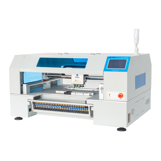
4. Machine intro CHMT560P4 machine structure as below: PIC4-1 (1) Nozzles: 4 heads with Juki nozzle (2) Down-looking camera: help positioning and for mark point calibration. (3) PCB clamping area: push the PCB on the end of left corner (4) Bulk IC material stack: put some loose-packed ICs (5) Full Touch screen: Touch pen or external USB mouse supported (6) Power: 220v or 110v, fuse inside it (7) Emergency button: press it will emergency stop, rotate to right it will pop out and... - Page 7 (12) Pneumatic Feeder: standard Yamaha feeder 8mm,12mm,16mm,24mm or Tube feeder.
-
Page 8: Start
5. Start Power on, press "confirm" on the screen, machine self-check and operation system start, below is home page. You can normal use it now. PIC5-1 (1) Alarm: on the left-side up triangle corner, used to check alarm detail and history. (2) Run: Used to manage and run the working file. -
Page 9: Run
6. RUN Home page --- Run, then you will see below image: PIC6-1 (1) Work file: current working file (2) New: create a new working file by yourself (3) Delete: delete work file (4) Edit: Edit the selected working file (5) Load: loading the selected working file and ready to run (6) Back: on the right-side up corner of the screen, used to back to last page. -
Page 10: Component Edit
PIC6-2 6.1.1. Component edit As above picture: (1) Component list (2) Add : add a new component on the end of the sheet (3) Insert: insert a new component before current component. (4) Delete: delete a component (5) Edit: edit the selected component (6) Save: after amend the component list you need to save, if not save in time, the save button will twinkle, then press the button and save, the twinkle end. - Page 11 PIC6-3 (1) Component number: on the left-side up corner (start from No.0). Press it you can select the component number. (2) Comp. ID: unique number, it won’t have 2 same comp. ID in one work file. M Stack: stack 1-30, 31-60 is normal feeder on the two sides of machine, stack 81-91 is for front bulk IC, stack...
- Page 12 setting. (If you create file manually, then you can press to adjust the position.) (10) Coordinate Y: usually work file generated from software no need to change the setting. (If you create file manually, then you can press to adjust the position.) (11) Skip comp: means not place this component...
-
Page 13: Material Stack Edit
PIC6-4 (1) Coordinate: X and Y’s coordinate is relative coordinates, means the coordinate after movement comparing with previous coordinate. (2) Vision: press this button exchange nozzle positioning and vision positioning, we suggest use vision positioning, nozzle position not that accurate. (3) Two point: means diagonal positioning, left-up corner and right-down corner. - Page 14 PIC6-5 (1) M Stack list (2) Add: add a new stack at the end of stack list; (3) Insert: insert a new stack (4) Delete: delete the selected stack, note: If delete this stack, the components will be delete as well. (5) Edit: edit selected stack, image as below: PIC6-6 Stack ID: 1-30 /31-60 for normal feeder, 81-91 for front bulk IC material, 101-119...
-
Page 15: Ic Tray Edit
ICs, please slow down the speed. Head: machine's head Angle compensation: you can set this to adjust the offset of angle. Comments: component information(for your own recognize) EC size X/Y: Aid function for camera vision calibrate, please keep it 0. Skip comp. - Page 16 PIC6-8 The stack number is from 81 -100, IC tray edit image as below: PIC6-9 (1) First IC center coord. X/Y: on the left-down side corner; (2) Last IC center coord. X/Y: on the right-up side corner; (3) X/Y direction number: The number of X/Y direction on IC (4) Start IC number: from number 0, IC number from left to right, up to down, when running, machine will start from your selected IC number.
-
Page 17: Panel Edit
6.1.4. Batch edit Batch is very convenient for same multi PCBs. There are 2 ways of Batch: "Coord" or "Array" positioning for PCB. "Coord" positioning according to the origin point of each PCB, "Coord" way is complicated but more accurate; "Array" positioning need to know how many PCB quantity for X and Y direction. -
Page 18: Pcb Calibrate
6.1.4.2. Array Array way image as below: PIC6-11 “Add skip”, it can skip some PCB and not mounting this PCB. “Create single” used to all the small PCB expand to one PCB, and save into a new work file. This function means you can adjust one single component in this new PCB. New work file will show “Single”... - Page 19 PIC6-12 Two ways of PCB calibrate: Component coordinate: the left-up corner component + the right-down corner component. Mark point: you can use 2 random components as Mark point, or use the mark point of this PCB directly, after positioning the two points, then all of other components of this PCB will be correction automatically.
-
Page 20: Run
PIC6-13 How to set Mark point Auto Calibration CHMT 5 series models: www.youtube.com/watch?v=HLL6ignTYyU 6.2. Run After work file completion, now you can run this file! Image as below:... - Page 21 PIC6-14 (1) Comp. ID (2) PCB ID: display current panel’s quantity. (3) Comp. cnt: component count. (4) PCB cnt: PCB count. (5) Ave. speed: average speed, cph. (6) Time cnt: time count. (7) Tray start: set the start number for IC tray Up-looking camera: press it will show the component by up-looking camera Working lamp...
-
Page 22: Test
7. Test Test used to test if each function in normal condition, you can’t edit value in this page: PIC7-1 (1) M Head 1/2 (2) Vacuum 1/2 (3) Rotate 1/2: press it rotate 180 degree; (4) Blow 1/2 (5) Up work light (6) Down work light (7) Work light (8) Material stack position: press it to selected pick position... -
Page 23: Set
8. Set PIC8-1 (16)Detect Vacuum: usually it keeps turn off, because you are enable "visual component detect" already, then this function is useless. This function means machine will detection of pick failure, and go pick again. (1) Visual assist: enable it camera vision system will working (2) Visual comp detect: if you turn on this function, system will pick again when it detects lack of materials. -
Page 24: System Set
(9) Clear system log (10)System comp. set: used to set component entire offset and angle compensation. 8.1. System set Note: in "system set", machine's value all set well by factory, usually don't need to change the value in system set. PIC8-2 (1) Head up camera position calibrate: this function is for adjusting the nozzle and camera position, usually factory will set well, don't need to change it. - Page 25 saved, then the setting only valid one time, next time after start machine, the setting will back to the previous setting. 8.2. Vacuum detection set Image as below: PIC8-3 Vacuum1-Suck gas: nozzle 1/2 change to suck gas condition, you can use your finger to block the nozzle tip, then you can see the changing current pressure.
-
Page 26: Backup And Recovery
current vacuum value smaller than threshold value1, then machine will judge nozzle not suck the component and it will suck again the component. If vacuum value bigger than threshold value1, then continue judge threshold value2. (5) M head 1/2 threshold 2: when machine suck component, if detect current vacuum value smaller threshold value2 (and also bigger than threshold value1), then machine will detect suction bad, and machine will throw material then suck again. -
Page 27: File Manage
parameters into USB. Note: After load in the system parameters, you need to press "Restore System Set", otherwise parameters didn't be activated. 9. File manage Manage the CSV file which generate from PCB software, and also the work file. PIC9-1 (1) File convert: Machine can not directly use the CSV file from PCB software. - Page 28 (1) Open existing PCB file, note: same component must have same designator, otherwise one component may occupies more than one material stack, since convert tool identifies different material stack by designator of component; (2) Set PCB origin, figure as below, note, for top layer setting origin in left bottom corner of PCB, for bottom layer setting origin in bottom right corner of PCB and check mirror image option when converting;...
-
Page 29: File Convert
PIC9-3 Image as below, select “CSV” and “Metric” in popup dialog box, click “OK” to finish. PIC9-4 9.2. File convert After generate the CSV file, all of generated CSV files in system are displayed in the list, then convert it to DPV file, picture as below:... -
Page 30: Csv File
PIC9-5 (1) Open: select the CSV to convert; (2) Delete: delete selected CSV file. 9.2.1. CSV File After selected one CSV file, display as below, all the components information included. PIC9-6 (1) Edit: edit information of selected component;... -
Page 31: Material Stack Station List
(2) Delete: delete selected component; (3) Convert set: Set convert to the top of the device or the underlying device, (the underlying device can set whether mirror or not.) (4) Convert: Convert CSV file to DPV work file, 9.2.2. Material stack station list Image as below, stack was generated according to the comment of the CSV file. -
Page 32: Components List
9.2.3. Components list PIC9-8 (1) Edit: Edit selected component; (2) Delete: Delete selected component; (3) Resort ID: The device number starting from 1 in ascending order; (4) Use dual nozzle1: Use nozzle1 and nozzle2 pick component in same material stack. NOTE: All components must 1,2,1,2... in order. (5) Use dual nozzle2: Means nozzle1 take component of stack1 and nozzle2 take component of stack2, then placing to two components. -
Page 33: Log
Log list as below, it records all the history of mounting. PIC10-1 (1) Log list: Each line records information of one running time; (2) Record: image as below, displays the detail running information: PIC10-2... -
Page 34: System Log
System log System log used to view all kinds of records generated by the system, image as show below. PIC11-1... -
Page 35: Maintenance
Maintenance 1. Close power switch and air source after working done, clearing the machine. 2. Add some grease to the bearings regularly according to actual condition, make sure machine working in smooth condition. -
Page 36: Warranty
3. Warranty Warranty range: SMT machine itself; Warranty period: 12 months; If there are problems in using, please contact us promptly, don’t repair by yourself to avoid damage to machine, or will lose your warranty; If accessories are breakdown, we will send a new one to you after receiving the broken one;...
Need help?
Do you have a question about the CHM-T560P4 and is the answer not in the manual?
Questions and answers