Advertisement
Quick Links
Advertisement

Subscribe to Our Youtube Channel
Related Manuals for Dive Gear Express DGX Gears XTRA


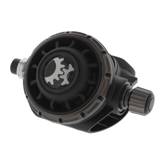
Summary of Contents for Dive Gear Express DGX Gears XTRA
- Page 1 DGX Gears XTRA Second Stage Service Manual...
- Page 2 Copyright © 2020 Dive Gear Express All Rights Reserved. Rev.6 Published 10/09/2020 Revision Date Changes 8/17/2020 Initial publication 10/09/2020 Edited photos for clarity and added part numbers; reordered photo numbering sequence Figs. 8-14 and Figs. 18-41; Tool List rearranged, added Scuba Tools link; renumbered 3.
- Page 3 Improper service of dive equipment can lead to severe injury or death. Dive Gear Express recommends that non-qualified individuals seek professional training/mentoring before attempting repairs or servicing on any diving equipment.
- Page 4 Cleaning and Rinsing - General Considerations (11) Cleaning and rinsing of the components should be done using clean, fresh water. If available, distilled water is recommended to maintain oxygen cleanliness. (12) Only use degreasers that leave no organic residue (e.g. Simple Green Free & Clear, Blue Gold Cleaner, or any clear liquid dish soap that does not contain scents or dyes).
-
Page 5: Inspection After Cleaning
Inspection After Cleaning (21) Before assembling the regulator, it is necessary to inspect all the cleaned components. Using the magnifying glass, ensure all parts are clean and contaminate-free, and check the components for damage that may have been hidden by corrosion or lubricant. Look for scratches that may affect the sealing of the regulator. - Page 6 This involves using a small clean plastic bag containing a small amount of lubricant. The O-ring is inserted into the bag, worked around to evenly coat with lube while squeezing off excess, then taken out of the bag and used in its location – Fig. 2. Fig.
- Page 7 2. Tool List (1) The tool list for the second stage is not as extensive as that for the first stage. They are still divided into Required and Recommended. Required tools are necessary for servicing the regulator. Recommended tools make servicing easier or more efficient, as well as lessen the chance of damage. Required Tools –...
- Page 8 Recommended Tools - Figs. 4 and 5 Magnehelic gauge with 0-3 inches scale - Fig.4, or a waterproof ruler/scale Soft rubber pad Magnifying glass Flashlight UV light Fig. 4 Fig. 5 (2) The In-Line Adjusting Tool with IP Gauge, IP Gauge and Brass O-Ring Pick Set can be found at Dive Gear Express using the link below.
- Page 9 3. Preliminary Testing (1) Preliminary testing of the regulator is necessary to identify any issues with the first and second stages and verify the overall regulator function. This testing will include: Visual inspection of the first and second stages Inspection of the hoses Intermediate Pressure (IP) check Cracking pressure and second stage negative pressure test Visual inspection is done to identify issues that could affect servicing and to ensure that pressurizing...
- Page 10 Caution Note: If the second stage is leaking even slightly, IP will be affected. If it is leaking, turn the adjustment knob to stop the flow or use a second stage that is not leaking when paired with the first stage. It is a clear indication that the second stage requires rebuilding if turning the adjustment knob does not stop the flow.
- Page 11 4. Second Stage Evaluation (1) The negative pressure test verifies the seals of the main and exhaust diaphragms, and verifies case integrity. With the supply pressure off, and attached to a cylinder, attempt a normal breath from the second stage. You should be unable to draw any air. If a flow is obtained, remove the second from the hose and try to draw air while sealing the hose inlet with your thumb.
- Page 12 5. Second Stage Disassembly (1) Ensure the system is depressurized. The use of small, clean containers to hold parts is recommended. (2) In the following steps, the part numbers from the schematic will be used with their description. The numbers on the photos also correspond with the parts list on the schematic. Items in the service kits are identified in the same way.
- Page 13 2. Remove the Retaining Nut (08) and the O-ring (09*) from its groove in the Case – Fig 8. Holding the Lever (20) down, slide/pull the Valve Spindle Assembly out of the case as one unit - Fig. 9. Fig. 8 Fig.
- Page 14 4. With the lever off, using the brass pick blunt end or another suitable tool, press the Spring Pin (21*) out of the Valve Spindle (19). Note that this may require some force to remove. Secure the spindle as needed. This will allow the Adjusting Screw (30) to be removed. Remove the Rubber Cap (35) from the Adjusting Screw.
- Page 15 6. Once you have removed the assembly from the Spindle, use the slotted end of the In-Line Adjusting Tool to remove the Orifice (15) from the Spindle. The photo below shows all the parts of the Spindle Assembly – Fig. 13. Fig.
- Page 16 8. Using the pinch method or a brass/plastic pick, remove all the O-rings from the Venturi Lever, Orifice, Valve Spindle, Shuttle Valve, Adjusting Screw, and Adjusting Spring - Fig. 15. Confirm that all are accounted for and segregate them with the other replaceable parts. Fig.
- Page 17 (3) The photographs below show the disassembled second stage – Fig. 18 and Second Stage Service Parts Kit – Fig. 19. All the parts not in the service kit need to be washed, rinsed and dried, as discussed previously. O-rings and washers that will be replaced with new from the service kit should be discarded. Fig.
- Page 18 6. Second Stage Assembly (1) Before starting the assembly of the second stage, complete a thorough inspection of all parts to be reused. Refer to the Overview Inspection section for details. At this time, open the service kit and lay out the parts.
- Page 19 2. Lubricate and install the O-ring (22*) on the Valve Spindle (19). Install the O-ring (23*) in the interior groove of the Spindle on the same side - Fig. 21. Fig. 21 3. Using the In-Line Tool, insert the Orifice (15) into the threaded end of the Spindle – Fig. 22, and when the threads engage, turn it inward 3-4 turns.
- Page 20 4. Assemble the Shuttle Valve, Spring (27), and Counter Balance Cylinder (28). With the assembly oriented, as shown in Fig. 24, insert it into the Spindle. Pay special attention to the position of the notch on the Shuttle Valve. This is where the Lever (20) engages the Shuttle Valve. It must be oriented in this manner.
- Page 21 6. Once the notch is lined up, carefully insert one tab of the lever to engage it and rotate the spindle so that the other leg of the lever drops into the corresponding window on the other side. Do not bend the legs of the lever! –...
- Page 22 8. Carefully insert the Adjusting Screw and Spring assembly into the Spindle and begin to screw it in. The lever will rise as this is done. Screw the assembly in until you can see clearly through the hole for the Spring Pin – Fig. 30. Fig.
- Page 23 10. Place the lubricated O-ring (17*) on the Venturi Lever (18) and slide it onto the Spindle/Lever assembly. Make sure that it moves freely around the Spindle. Note the position of the lever relative to the air outlet -Fig. 32. Fig.
- Page 24 12. Turn the Case so that the Adjusting Spring can be seen – Fig. 35. Install the Rubber Cap (35) onto the Adjusting Screw to cover the Spring - Fig. 36. Fig. 35 Fig. 36 13. Using the In-Line Adjusting Tool, while depressing the Lever, turn the Orifice so that the Lever is even with the face of the Case.
- Page 25 14. Assemble the Diaphragm (06*) and Disc (05*) by gently stretching the Diaphragm and allowing it to go into the groove – Fig. 38. Make sure there are no wrinkles and that the rubber is evenly seated. Place the assembly in the Case. Place the Diaphragm Cover (04) in position – Fig. 39. Fig.
- Page 26 6. Second Stage Testing and Adjustment (1) Second stage testing and adjustment can be accomplished by using a regulated supply or any cylinder of air. There is no required supply pressure due to the second stage being supplied by a first stage delivering air at the Intermediate Pressure (IP).
- Page 27 7. Testing for Cracking Pressure (1) Cracking pressure is the effort required to depress the lever and allow air to flow through the second stage. It is measured in inches of water. A magnehelic gauge is one method of measuring this pressure. The gauge is attached to the second stage, and a normal breath is taken.
- Page 28 (4) General Troubleshooting – Not all possibilities may be noted. No airflow Check supply pressure; Orifice too tight; Lever not seated and has dropped Free Flowing Orifice adjusted too loosely; LP Seat bad; excessive IP Hard to inhale Lever bent or restricted; adjusted with a too high cracking pressure Wet breathing Cracked Case;...
Need help?
Do you have a question about the DGX Gears XTRA and is the answer not in the manual?
Questions and answers