Table of Contents
Advertisement
Quick Links
Advertisement
Chapters
Table of Contents

Subscribe to Our Youtube Channel
Related Manuals for Cambium Networks PTP 800 Series


Summary of Contents for Cambium Networks PTP 800 Series
- Page 1 Cambium PTP 800 Series User Guide System Release 800-05-02...
- Page 2 Accuracy While reasonable efforts have been made to assure the accuracy of this document, Cambium Networks assumes no liability resulting from any inaccuracies or omissions in this document, or from use of the information obtained herein. Cambium reserves the right to make changes to any products described herein to improve reliability, function, or design, and reserves the right to revise this document and to make changes from time to time in content hereof with no obligation to notify any person of revisions or changes.
-
Page 3: Important Safety Information
PTP 800 Series User Guide Important safety information This section describes important safety guidelines that must be observed by personnel installing or operating PTP 800 equipment. To prevent loss of life or physical injury, observe the safety guidelines in this section. - Page 4 I m port ant safet y inform at ion Electrical safety The power cable connections must meet International Electrotechnical Commission (IEC) safety standards. Always power down and unplug the equipment before servicing. When using alternative DC supplies, such as battery-backed DC power source, the supply must be SELV rated.
-
Page 5: Table Of Contents
PTP 800 Series User Guide Contents I m por t a n t sa f e t y in f or m a t ion ................... I Abou t Th is Use r Guid e ..................... 1 General information ........................2 Version information ......................... - Page 6 Cont ent s IRFU availability ......................... 1-19 IRFU configuration options ....................1-20 IRFU interfaces ........................1-25 Further reading on the IRFU ....................1-26 Antennas and couplers......................1-27 Antennas ..........................1-27 Remote mounting kits (RMKs).................... 1-29 Coupler mounting kits ......................1-30 Direct mount dual-polar antennas ..................
- Page 7 PTP 800 Series User Guide Email alerts ......................... 1-54 SNMP ..........................1-54 Simple Network Time Protocol (SNTP) ................1-56 SNMPv3 security ........................ 1-56 System logging (syslog) ...................... 1-59 AES license .......................... 1-60 Login information ........................ 1-61 Flexible capacity upgrades ....................1-61 Software upgrade ........................
- Page 8 Cont ent s Data network planning ......................2-18 Management mode ......................2-18 VLAN membership ......................2-19 Priority for management traffic ..................2-19 IP interface .......................... 2-19 Quality of service for bridged Ethernet traffic..............2-19 Fast Ethernet port shutdown ....................2-21 Security planning ........................
- Page 9 Ordering capacity upgrades ....................2-97 Cha pt e r 3 : Le ga l in f or m a t ion ..................3 - 1 Cambium Networks end user license agreement ..............3-2 Acceptance of this agreement ....................3-2 Definitions ..........................3-2 Grant of license ........................
- Page 10 Cont ent s General wireless specifications ..................4-19 Frequency bands and channel separation ................. 4-20 Capacity, transmit power and sensitivity ................4-22 Data network specifications ..................... 4-71 Ethernet interfaces ......................4-71 Ethernet bridging ....................... 4-72 Syslog message formats ......................4-73 Format of syslog server messages ..................
- Page 11 PTP 800 Series User Guide Fitting an N type connector to an IF cable ................ 5-38 Connecting the ODU to the top LPU .................. 5-42 Weatherproofing an N type connector ................5-45 Hoisting the main IF cable ....................5-49 Installing and grounding the main IF cable ............... 5-52 Making an IF cable ground point ..................
- Page 12 Cont ent s Installing a protection cable ....................5-94 Replacing IRFU components ....................5-95 Replacing a transceiver ...................... 5-97 Replacing a branching unit....................5-100 Replacing filters ........................ 5-102 Replacing a fan assembly ....................5-103 Replacing an RF cable ...................... 5-104 Ch a pt e r 6 : Con f igu r a t ion a nd a lign m e n t ..............
- Page 13 PTP 800 Series User Guide Configuring RADIUS authentication .................. 6-50 Task 6: Configuring protection ....................6-53 Configuring unprotected links .................... 6-53 Configuring 1+1 Hot Standby links ................... 6-54 Upgrading an unprotected link to 1+1 Hot Standby ............6-61 Task 7: Configuring wireless interface ..................6-63 Prerequisites for the Installation Wizard ................
- Page 14 Cont ent s Configuring quality of service ..................6-111 Task 15: Connecting link to the network ................6-114 Connecting to the network ....................6-114 Setting the real-time clock ....................6-115 Saving the system configuration ..................6-119 Configuring for FIPS 140-2 applications ................6-121 Prerequisites for FIPS 140-2 configuration ..............
- Page 15 PTP 800 Series User Guide Changing AES encryption keys ..................7-53 Changing the log-out timer ....................7-56 Managing performance ......................7-57 Checking system statistics and counters ................7-57 Resetting system statistics and counters ................7-62 Viewing diagnostics ......................7-62 Using the diagnostics plotter ....................7-63 Downloading diagnostic data .....................
- Page 16 Cont ent s Check RFU status ......................... 8-9 Transmitter status ......................8-10 Antenna alignment ......................8-10 Check transmit and receive frequencies ................8-11 Check waveguide and antennas ..................8-11 Check link status ......................... 8-11 Check IRFU status LEDs ....................8-12 Testing protection switchover ....................
- Page 17 PTP 800 Series User Guide List of Figures Figure 1 Typical PTP 800 deployment (ODU platform) ..............1-5 Figure 2 Typical PTP 800 deployment (IRFU platform) ..............1-5 Figure 3 PTP 800 CMU ........................1-8 Figure 4 CMU front panel ....................... 1-9 Figure 5 ODU-A front view ......................
- Page 18 List of Figures Figure 32 Inactive unit frame forwarding – in-band management ..........1-48 Figure 33 Protocol layers between Ethernet and wireless interfaces ......... 1-49 Figure 34 Protocol layers between external interfaces and the management agent ....1-50 Figure 35 Receive Diversity Ethernet frames ................1-67 Figure 36 Tamper evident label on rear edge of CMU ..............
- Page 19 PTP 800 Series User Guide Figure 68 Waveguide flanges – 6 GHz ..................4-12 Figure 69 Waveguide flanges – 7 to 15 GHz ................. 4-13 Figure 70 Waveguide flanges – 18 to 38 GHz................4-14 Figure 71 Waveguide flanges – 11 GHz tapered transition ............4-14 Figure 72 European Union compliance label ................
- Page 20 List of Figures Figure 105 Out-of-band protection splitter connections .............. 5-90 Figure 106 Redundant copper interface connections ..............5-91 Figure 107 Redundant fiber interface connections ..............5-92 Figure 108 Optical Y interface connections ................. 5-93 Figure 109 Protection cable connections ..................5-94 Figure 110 IRFU components (example) ..................
- Page 21 PTP 800 Series User Guide Figure 142 Step 1: Enter equipment details page (ODU) ............6-65 Figure 143 Step 1: Enter equipment details page (IRFU) ............6-66 Figure 144 Step 2: Radio License Configuration page (fixed modulation) ........6-69 Figure 145 Step 2: Radio License Configuration page (FCC adaptive modulation) ....6-70 Figure 146 Step 2: Radio License Configuration page (ETSI adaptive modulation) ....
- Page 22 List of Figures Figure 179 System Administration Login page ................7-2 Figure 180 Menu and System Summary page (wireless link up) ..........7-3 Figure 181 System Summary page ....................7-6 Figure 182 System Status page (unprotected link) ................ 7-8 Figure 183 System Status page (1+1 Hot Standby link) ............... 7-9 Figure 184 Web browser with default title ...................
- Page 23 PTP 800 Series User Guide List of Tables Table 1 PTP 800 licensed bands and frequencies (ODU-A platform) ..........1-3 Table 2 PTP 800 licensed bands and frequencies (ODU-B platform)..........1-3 Table 3 PTP 800 licensed bands and frequencies (IRFU platform) ..........1-4 Table 4 CMU interfaces ........................
- Page 24 List of Tables Table 32 Antennas: 26 GHz dual polarization ................2-67 Table 33 Antennas: 28 GHz single polarization ................2-67 Table 34 Antennas: 28 GHz dual polarization ................2-67 Table 35 Antennas: 32 GHz single polarization ................2-68 Table 36 Antennas: 32 GHz dual polarization ................2-68 Table 37 Antennas: 38 GHz single polarization ................
- Page 25 PTP 800 Series User Guide Table 69 IRFU upgrade kits – 6 GHz and 11 GHz ................ 2-94 Table 70 Antennas and antenna accessories for IRFU deployments ........... 2-95 Table 71 Copper network cables and connectors................. 2-96 Table 72 Fiber network cables and connectors ................2-96 Table 73 Single-step capacity upgrades (per unit) ...............
- Page 26 List of Tables Table 106 Upper 6 GHz FCC with 10 MHz bandwidth ..............4-26 Table 107 Upper 6 GHz FCC with 30 MHz bandwidth ..............4-26 Table 108 Upper 6 GHz ETSI with 7 MHz channel separation ............ 4-27 Table 109 Upper 6 GHz ETSI with 14 MHz channel separation ..........
- Page 27 PTP 800 Series User Guide Table 143 15 GHz ETSI with 56 MHz channel separation ............4-45 Table 144 18 GHz FCC and Canada with 10 MHz bandwidth (ODU-A) ........4-46 Table 145 18 GHz FCC and Canada with 10 MHz bandwidth (ODU-B) ........4-46 Table 146 18 GHz FCC and Canada with 20 MHz bandwidth (ODU-A) ........
- Page 28 List of Tables Table 180 26 GHz ETSI with 14 MHz channel separation ............4-62 Table 181 26 GHz ETSI with 28 MHz channel separation ............4-63 Table 182 26 GHz ETSI with 56 MHz channel separation ............4-63 Table 183 28 GHz ETSI with 7 MHz channel separation ............. 4-64 Table 184 28 GHz ETSI with 14 MHz channel separation ............
- Page 29 PTP 800 Series User Guide Table 217 IRFU waveguide and flange specifications ..............5-73 Table 218 Selecting network interfaces for 1+1 Hot Standby links ..........5-89 Table 219 Tools required for IRFU component replacement ............5-97 Table 220 RF cable connections (1+1 Tx MHSB / Rx SD example) ........... 5-105 Table 221 IP interface attributes ....................
- Page 30 List of Tables Table 254 Wireless Link Status attribute values ................7-11 Table 255 Transmit Modulation Selection Detail attribute values ..........7-11 Table 256 Data Port Status attribute values ................7-12 Table 257 Management Port Status attribute values ..............7-12 Table 258 Browser Title attribute variables .................
-
Page 31: About This User Guide
PTP 800 Series User Guide About This User Guide This guide describes the planning, installation and operation of the Cambium PTP 800. It is intended for use by the system designer, system installer and the system administrator. Users of this guide should have knowledge of the following areas: •... -
Page 32: General Information
System Release 800-05-00 002v000 May 2012 System Release 800-05-00 (minor revision) 003v000 Jul 2012 System Release 800-05-01 004v000 Oct 2012 System Release 800-05-02 Contacting Cambium Networks Support website: http://www.cambiumnetworks.com/support Main website: http://www.cambiumnetworks.com Sales enquiries: solutions@cambiumnetworks.com Support enquiries: support@cambiumnetworks.com Telephone number list: http://www.cambiumnetworks.com/contact.php... - Page 33 General inform at ion Purpose Cambium Networks Point-To-Point (PTP) documents are intended to instruct and assist personnel in the operation, installation and maintenance of the Cambium PTP equipment and ancillary devices. It is recommended that all personnel engaged in such activities be properly trained.
-
Page 34: Problems And Warranty
Problem s and warrant y About This User Guide Problems and warranty Reporting problems If any problems are encountered when installing or operating this equipment, follow this procedure to investigate and report: Search this document and the software release notes of supported releases. Visit the support website. - Page 35 PTP 800 Series User Guide Problem s and warrant y Portions of Cambium equipment may be damaged from exposure to electrostatic discharge. Use precautions to prevent damage. phn- 2513_004v000 ( Oct 2012)
-
Page 36: Security Advice
Securit y advice About This User Guide Security advice Cambium Networks systems and equipment provide security parameters that can be configured by the operator based on their particular operating environment. Cambium recommends setting and using these parameters following industry recognized security practices. -
Page 37: Warnings, Cautions, And Notes
Warnings, caut ions, and not es Warnings, cautions, and notes The following describes how warnings and cautions are used in this document and in all documents of the Cambium Networks document set. Warnings Warnings precede instructions that contain potentially hazardous situations. Warnings are used to alert the reader to possible hazards that could cause loss of life or physical injury. -
Page 38: Caring For The Environment
About This User Guide Caring for the environment The following information describes national or regional requirements for the disposal of Cambium Networks supplied equipment and for the approved disposal of surplus packaging. In EU countries The following information is provided to enable regulatory compliance with the European Union (EU) directives identified and any amendments made to these directives when using Cambium equipment in EU countries. -
Page 39: Licensing Requirements
United States of America This device has been verified by Cambium Networks as being in compliance with the requirements of the rules of the Federal Communications Commission (FCC), 47 C.F.R. Part 101, and may not be operated without a station license. In the United States such licenses are issued by the FCC to entities other than agencies of the United States government. - Page 40 Licensing requirem ent s About This User Guide phn- 2513_004v000 ( Oct 2012)
-
Page 41: Chapter 1: Product Description
PTP 800 Series User Guide Chapter 1: Product description This chapter provides a high level description of the PTP 800 product. It describes in general terms the function of the product, the main product variants and typical deployment. It also describes the main hardware components. -
Page 42: Overview
Overview Chapt er 1: Product descript ion Overview Cambium PTP 800 Licensed Ethernet Microwave products are designed for Ethernet bridging at up to 368 Mbps over licensed point-to-point microwave links in selected licensed bands from 6 GHz to 38 GHz. The products offer exceptional cost efficiency and scalability. -
Page 43: Supported Bands And Frequencies
PTP 800 Series User Guide Overview Supported bands and frequencies The PTP 800 outdoor unit (ODU) platform supports the licensed bands and frequencies listed in Table 1 (ODU-A) or Table 2 (ODU-B). The PTP 800 indoor RF unit (IRFU) platform... -
Page 44: Typical Users And Applications
Overview Chapt er 1: Product descript ion Ta ble 3 PTP 800 licensed bands and fr equencies ( I RFU plat form ) Lice n se d b a n d Re gion s Fr e q u e ncy cove r a g e Lower 6 GHz FCC, IC 5.925 –... -
Page 45: System Components
PTP 800 Series User Guide Overview System components The main components of the PTP 800 are shown in Figure 1 (ODU platform) and Figure 2 (IRFU platform). Figu r e 1 Typical PTP 800 deploym ent ( ODU plat form ) -
Page 46: Link Types
Overview Chapt er 1: Product descript ion The main components are: • Compact modem unit (CMU): The CMU converts data signals between Ethernet frames and a modulated intermediate frequency (IF) carrier. • Outdoor unit (ODU): The ODU converts signals between a modulated intermediate frequency (IF) and radio band frequencies. - Page 47 PTP 800 Series User Guide Overview For more information about these link types refer to: • Planning 1+0 links on page 2-30 • Planning 1+1 Hot Standby links on page 2-35 • Planning 2+0 links on page 2-49 phn- 2513_004v000 ( Oct 2012)
-
Page 48: Compact Modem Unit (Cmu)
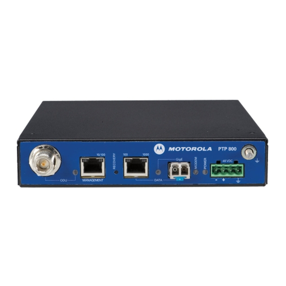
Com pact m odem unit ( CMU) Chapt er 1: Product descript ion Compact modem unit (CMU) This section describes the PTP 800 CMU and its interfaces. CMU description The PTP 800 compact modem unit (CMU) (Figure 3) is mounted indoors and provides the Ethernet interface to the network. -
Page 49: Cmu Interfaces
PTP 800 Series User Guide Com pact m odem unit ( CMU) CMU interfaces The CMU front panel interfaces are illustrated in Figure 4 and described in Table 4. The CMU front panel indicator LEDs and their states are described in... - Page 50 Com pact m odem unit ( CMU) Chapt er 1: Product descript ion I n t e r fa ce Fu n ct ion Recovery This switch is used to start the CMU in recovery mode. Recovery mode provides a means to recover from serious configuration errors including lost or forgotten passwords and unknown IP addresses.
-
Page 51: Table 5 Cmu Led States
PTP 800 Series User Guide Com pact m odem unit ( CMU) Ta ble 5 CMU LED st at es I nd ica t or St a t e D e scr ipt ion Green steady RFU ready for use and transmitting... -
Page 52: Further Reading On The Cmu
Com pact m odem unit ( CMU) Chapt er 1: Product descript ion Further reading on the CMU For more information on the CMU, refer to the following: • Power supply considerations on page describes how to plan the power supply to the PTP 800 CMU. -
Page 53: Outdoor Unit (Odu)
PTP 800 Series User Guide Out door unit ( ODU) Outdoor unit (ODU) This section describes the PTP 800 ODU and its interfaces. ODU description The PTP 800 outdoor unit (ODU) provides the necessary frequency conversion and amplification of signals which pass between the CMU and antenna. -
Page 54: Odu Interfaces
Out door unit ( ODU) Chapt er 1: Product descript ion The term ‘ODU’ covers both ODU-A and ODU-B. ODU interfaces The ODU interfaces are illustrated in: Figure Figure Figure Figure 8 Figure They are described in Table Figu r e 5 ODU- A front view 1- 14 phn- 2513_004v000 ( Oct 2012) - Page 55 PTP 800 Series User Guide Out door unit ( ODU) Figu r e 6 ODU- B front view Figu r e 7 ODU r ear view phn- 2513_004v000 ( Oct 2012) 1- 15...
-
Page 56: Table 6 Odu Interfaces
Out door unit ( ODU) Chapt er 1: Product descript ion Figu r e 8 ODU- A side v iew Figu r e 9 ODU- B side v iew Ta ble 6 ODU int erfaces I n t e r fa ce Fu n ct ion Waveguide polarization This indicates the orientation of the waveguide... -
Page 57: Further Reading On The Odu
PTP 800 Series User Guide Out door unit ( ODU) I n t e r fa ce Fu n ct ion Ground connector This is used to ground the ODU to the top lightning protection unit (LPU). RSSI connector The received signal strength indication (RSSI) -
Page 58: Indoor Rf Unit (Irfu)
I ndoor RF unit ( I RFU) Chapt er 1: Product descript ion Indoor RF unit (IRFU) This section describes the PTP 800 IRFU and its interfaces. IRFU description The PTP 800 indoor RF unit (IRFU) (Figure 10) converts signals between a modulated intermediate frequency (IF) and radio band frequencies for transmission over a line-of- sight link. -
Page 59: Transceivers
The result is a fixed IF signal which is passed to the CMU for demodulation. Each transceiver is powered via its own dedicated power socket. Cambium Networks do not provide the power supply, but they do provide the power connector. For power supply... -
Page 60: Irfu Configuration Options
I ndoor RF unit ( I RFU) Chapt er 1: Product descript ion IRFU configuration options IRFUs are available with the following optional configurations: This consists of a single transceiver with the branching unit providing a single waveguide interface (Figure 11). - Page 61 PTP 800 Series User Guide I ndoor RF unit ( I RFU) 1+1 Tx MHSB (with equal or unequal receiver coupling) This option consists of two transceivers with the branching unit providing a single waveguide interface for connection to an antenna (Figure 12).
- Page 62 I ndoor RF unit ( I RFU) Chapt er 1: Product descript ion 1+0 Tx MHSB Ready (with equal or unequal receiver coupling) This option consists of a single transceiver and a single waveguide interface (Figure 13), but the branching unit is ready for connection of a second transceiver if an upgrade to a full 1+1 Tx MHSB is required at a later date.
- Page 63 PTP 800 Series User Guide I ndoor RF unit ( I RFU) 1+1 Tx MHSB / Rx SD This option consists of two transceivers with the branching unit providing two waveguide interfaces (Figure 14). As well as providing MHSB operation in the event of single point equipment failure, it also provides Receive Spatial Diversity by providing a second waveguide interface which connects to a diverse antenna.
- Page 64 I ndoor RF unit ( I RFU) Chapt er 1: Product descript ion This option consists of two transceivers with the branching unit providing a single waveguide interface (Figure 15). This option provides two parallel 1+0 links which share the same antenna. Both transceivers will simultaneously transmit and receive through the same waveguide interface.
-
Page 65: Irfu Interfaces
PTP 800 Series User Guide I ndoor RF unit ( I RFU) IRFU interfaces The IRFU transceiver interfaces are illustrated in Figure 16 and described in Table Figu r e 1 6 I RFU t ransceiver int erfaces Ta ble 7 I RFU t ransceiver int erfaces... -
Page 66: Further Reading On The Irfu
I ndoor RF unit ( I RFU) Chapt er 1: Product descript ion I n t e r fa ce Fu n ct ion RX Connector For connecting the transceiver (receive) to the BU via an RF cable with SMA connectors. RX SD Connector For connecting the transceiver (receive diversity) to the BU via an RF cable with SMA connectors. -
Page 67: Antennas And Couplers
PTP 800 Series User Guide Ant ennas and couplers Antennas and couplers This section describes the PTP 800 antennas, couplers and remote mounting kit. Antennas A typical antenna is shown in Figure Figu r e 1 7 Typical PTP 800 ant enna wit h ODU ( Cam bium direct m ount int erface) - Page 68 Ant ennas and couplers Chapt er 1: Product descript ion Figu r e 1 8 Direct m ount m echanical int erface Figu r e 1 9 ODU clipped ont o direct m ount m echanical int erface Figu r e 2 0 Rem ot e m ount ant enna waveguide int erface 1- 28 phn- 2513_004v000 ( Oct 2012)
-
Page 69: Remote Mounting Kits (Rmks)
PTP 800 Series User Guide Ant ennas and couplers Antenna polarization Antennas can be provided as single polar or dual polar: • Single polar : A single polar antenna provides a single interface to the RFU. The antennas are normally supplied with vertical polarization. For horizontal polarization, the antennas can be modified by the user using the instructions provided. -
Page 70: Coupler Mounting Kits
Ant ennas and couplers Chapt er 1: Product descript ion Figu r e 2 1 RMK showing t he ODU int erface Figu r e 2 2 RMK showing t he wav eguide int erface Coupler mounting kits Applies to ODU deployments only. The signals from two ODUs can be coupled to a single antenna. - Page 71 PTP 800 Series User Guide Ant ennas and couplers Coupler mounting kits are provided in two options: • Symmetric coupler mounting kits: This option splits the power evenly between the two ODUs. A nominal 3 dB is lost in each arm of the coupler.
-
Page 72: Direct Mount Dual-Polar Antennas
Ant ennas and couplers Chapt er 1: Product descript ion Figu r e 2 4 Two ODUs and ant enna m ount ed on a coupler Direct mount dual-polar antennas Applies to ODU deployments only. Direct mount dual-polar antennas are only used in 2+0 cross-polar direct mount configurations. -
Page 73: Further Reading On Antennas And Couplers
PTP 800 Series User Guide Ant ennas and couplers Further reading on antennas and couplers For more information on antennas and antenna accessories, refer to the following: • Site selection on page describes how to select a site for the antenna. -
Page 74: Cabling And Lightning Protection
The PTP 800 Series is not designed to survive direct lightning strikes. For this reason the antenna and ODU should not be installed at the highest point in a localized area. See Grounding and lightning protection on page 2-7. - Page 75 PTP 800 Series User Guide Cabling and light ning prot ect ion Figu r e 2 6 Cable grounding kit for 1/ 4" and 3/ 8" cable Lightning protection units (LPUs) The PTP 800 LPU end kit (Figure 27) is required for IF cables. One LPU is installed next to the ODU and the other is installed near the building entry point.
-
Page 76: Further Reading On Cabling And Lightning Protection
Cabling and light ning prot ect ion Chapt er 1: Product descript ion Further reading on cabling and lightning protection For more information on cabling and lightning protection, refer to the following: • Maximum IF cable length on page gives the maximum permitted lengths of IF cables in PTP 800 installations. -
Page 77: Wireless Operation
PTP 800 Series User Guide Wireless operat ion Wireless operation This section describes how the PTP 800 wireless link is operated, including modulation modes, power control and security. Channel separation The PTP 8 0 wireless link supports the following channel separations: •... -
Page 78: Modulation Modes
Wireless operat ion Chapt er 1: Product descript ion Modulation modes The PTP 800 wireless link operates using single carrier modulation with the following fixed modulation modes: • QPSK • 8PSK • 16QAM • 32QAM • 64QAM • 128QAM • 256QAM The available selection of modulation modes varies depending on band, region and channel bandwidth. -
Page 79: Maximum Receive Power
PTP 800 Series User Guide Wireless operat ion Automatic adjustment of the transmitter can be enabled or disabled using the Automatic Transmitter Power Control attribute on the Configuration page of the web-based interface. This attribute must have the same setting at both ends of the link. -
Page 80: Maximum Transmit Power
Wireless operat ion Chapt er 1: Product descript ion Maximum transmit power Maximum transmit power is the maximum power that the PTP 800 is permitted to generate at the waveguide interface assuming that ATPC is disabled, or the link loss is high enough such that ATPC is not activated. - Page 81 PTP 800 Series User Guide Wireless operat ion • Comparing actual to predicted performance on page 6-110 describes how to check that a newly installed link is achieving predicted levels of performance. • Disabling and enabling the wireless interface on page...
-
Page 82: Ethernet Bridging
Customer network Transparent Ethernet service The PTP 800 Series provides an Ethernet service between the data port at a local CMU and the data port at an associated remote CMU. The Ethernet service is based on conventional layer two transparent bridging, and is equivalent to the Ethernet Private Line (EPL) service defined by the Metro Ethernet Forum (MEF). -
Page 83: Management Network
Et hernet bridging Quality of service for bridged Ethernet traffic The PTP 800 Series supports eight traffic queues for Ethernet frames waiting for transmission over the wireless link. Ethernet frames are classified by inspection of the Ethernet destination address, the Ethernet priority code point in the outermost VLAN tag, the Differentiated Services Code Point (DSCP) in an IPv4 or IPv6 header, or the Traffic Class in an MPLS header. - Page 84 Et hernet bridging Chapt er 1: Product descript ion VLAN membership The management agent can be configured to transmit and receive either untagged, priority-tagged, C-tagged (IEEE 802.1Q) or S-tagged (IEEE 801.ad) frames. S-tagged frames must be single tagged, in other words, an S-tag with no encapsulated C-tag. The VLAN ID can be 0 (priority tagged) or in the range 1 to 4094.
- Page 85 Wireless link down alert The PTP 800 Series can be configured to alert a ‘loss of link’ to the connected network equipment. It does this by means of a brief disconnection of the copper data port or fiber data port.
-
Page 86: Protocol Model
Et hernet bridging Chapt er 1: Product descript ion The wireless link down alert can be deployed in networks which provide alternative traffic routes in the event of failure. Spanning Tree Protocol (STP) and Ethernet Automatic Protection Switching (EAPS) are two protocols which are commonly deployed in such complex networks and both react to the wireless link down alert. - Page 87 PTP 800 Series User Guide Et hernet bridging Figu r e 2 8 Forwarding behavior in out - of- band local m anagem ent m ode Figu r e 2 9 Forwarding behavior in out - of- band m anagem ent m ode...
- Page 88 Et hernet bridging Chapt er 1: Product descript ion Forwarding behavior for 1+1 Hot Standby links Forwarding behavior for the active CMU is as for a non-protected link. Forwarding behavior for the inactive CMU in a 1+1 Hot Standby link requires management data to be routed to the Ethernet management port (Figure 31) or data port...
- Page 89 PTP 800 Series User Guide Et hernet bridging Protocol layers Protocol layers involved in bridging between Ethernet and wireless interfaces are shown in Figure 33. Protocol layers involved in bridging between external interfaces and the management agent are shown in Figure 34.
-
Page 90: Further Reading On Ethernet Bridging
Et hernet bridging Chapt er 1: Product descript ion Figu r e 3 4 Prot ocol layer s bet ween ext ernal int er faces and t he m anagem ent agent Further reading on Ethernet bridging For more information on Ethernet bridging, refer to the following: •... -
Page 91: System Management
PTP 800 Series User Guide Syst em m anagem ent System management This section introduces the PTP 800 management system, including the web interface, installation, configuration, alerts and upgrades. Management agent PTP 800 equipment is managed through an embedded management agent. Management workstations, network management systems or PCs can be connected to this agent using an in-band mode, or a choice of two out-of-band modes. - Page 92 Syst em m anagem ent Chapt er 1: Product descript ion HTTPS/TLS requires installation of a private key and a public key certificate where the common name of the subject in the public key certificate is the IP address or host name of the PTP 800 unit.
-
Page 93: Installation Wizard
PTP 800 Series User Guide Syst em m anagem ent Installation wizard The web-based interface includes an Installation wizard. This feature simplifies the process of entering initial configuration details, setting the system into alignment mode, achieving the lowest possible link loss through correct antenna alignment, and reporting on the performance of the installed link. -
Page 94: Email Alerts
Syst em m anagem ent Chapt er 1: Product descript ion Email alerts The management agent can be configured to generate alerts by electronic mail when any of the following events occur: • Wireless link up • Wireless link down •... - Page 95 PTP 800 Series User Guide Syst em m anagem ent The PTP 800 enterprise MIB is available for download in the application software package from the support web page (see Contacting Cambium Networks on page 2). Further details of the standard SNMP MIB objects supported by PTP 800 are provided in Standard SNMP MIBs on page 4-77.
-
Page 96: Simple Network Time Protocol (Sntp)
Syst em m anagem ent Chapt er 1: Product descript ion Simple Network Time Protocol (SNTP) The clock supplies accurate date and time information to the system. It can be set to run with or without a connection to one or two network time servers (SNTP). It can be configured to display local time by setting the time zone and daylight saving in the Time Configuration web page. - Page 97 PTP 800 Series User Guide Syst em m anagem ent View-based access control model PTP 800 supports the SNMPv3 view-based access control model (VACM) with a single context. The context name is the empty string. The context table is read-only, and cannot be modified by users.
- Page 98 Syst em m anagem ent Chapt er 1: Product descript ion The default user is created with a view of the entire MIB, requiring authentication initial for SET operations. There is no access for template users. VACM grants access for requests sent with more than the configured security level. The default user will have read/write access to the whole of the MIB.
-
Page 99: System Logging (Syslog)
PTP 800 Series User Guide Syst em m anagem ent • SNMPv3 Security Management is changed from MIB-based to web-based. Additionally, all SNMP user accounts are disabled when the authentication protocol, the privacy protocol, or the security level is changed. -
Page 100: Aes License
MAC address of the target CMU into the PTP License Key Generator web page, which may be accessed from the support web page (see Contacting Cambium Networks on page 2). The License Key Generator creates a new license key that is delivered by email. The license key must be installed on the CMU. -
Page 101: Login Information
PTP 800 Series User Guide Syst em m anagem ent Login information PTP 800 optionally provides details of the most recent successful login, and the most recent unsuccessful login attempt, for each user of the web-based interface. Flexible capacity upgrades The maximum data throughput capacity of the PTP 800 wireless link is the lower of the wireless link capacity and the data capacity limit set by the PTP 800 license key. -
Page 102: Software Upgrade
Syst em m anagem ent Chapt er 1: Product descript ion Software upgrade The management agent supports application software upgrade using the web-based interface. PTP 800 software images are digitally signed, and the CMU will accept only images that contain a valid Cambium PTP digital signature. The CMU always requires a reboot to complete a software upgrade. -
Page 103: Further Reading On System Management
PTP 800 Series User Guide Syst em m anagem ent Options in recovery mode are as follows: • Load new main application software. • Reset all configuration data to factory default. This option resets IP and Ethernet configuration, and erases (zeroizes) critical security parameters. -
Page 104: 1+1 Hot Standby Link Protection
1+ 1 Hot St andby link prot ect ion Chapt er 1: Product descript ion 1+1 Hot Standby link protection This section is an overview of the concept, operation and interfaces of 1+1 Hot Standby links. 1+1 Hot Standby overview The 1+1 Hot Standby feature provides an option for protecting against a single point equipment failure. -
Page 105: 1+1 Hot Standby Link Antenna Options
PTP 800 Series User Guide 1+ 1 Hot St andby link prot ect ion The other CMU and ODU / IRFU transceiver are called the inactive units and these will remain on standby waiting to take over in case of a failure of the active units. If a failure does occur, an automatic protection switch will take place and the previously inactive units will take over as the active units. -
Page 106: Bridging In 1+1 Links
1+ 1 Hot St andby link prot ect ion Chapt er 1: Product descript ion Two antennas per end The ODUs installed at the same end of a 1+1 Hot Standby link can be connected to separate antennas. Although antennas with different gains or mounting options may be deployed, they must have the same polarization. -
Page 107: Receive Diversity
PTP 800 Series User Guide 1+ 1 Hot St andby link prot ect ion Receive Diversity Receive Diversity improves link availability by providing each end of a wireless link with multiple observations of the signal which has been transmitted from the remote end of the link. - Page 108 1+ 1 Hot St andby link prot ect ion Chapt er 1: Product descript ion Effects of Receive Diversity on 1+1 operation In almost all aspects, the 1+1 Hot Standby feature operates in the same way regardless of whether or not Receive Diversity has been enabled. Of most significance is the concept of the Active and Inactive units, where it is the Active ODU or IRFU transceiver which always radiates at the antenna and the Active CMU which forwards Ethernet frames to the network.
-
Page 109: Further Reading On 1+1 Hot Standby
PTP 800 Series User Guide 1+ 1 Hot St andby link prot ect ion Further reading on 1+1 Hot Standby For more information on 1+1 Hot Standby link protection, refer to the following: • Planning 1+1 Hot Standby links on page... -
Page 110: Fips 140-2
FI PS 140- 2 Chapt er 1: Product descript ion FIPS 140-2 This section describes the (optional) FIPS 140-2 cryptographic mode of operation. PTP 800 provides an optional secure cryptographic mode of operation validated to Level 1 of Federal Information Processing Standards Publication 140-2. FIPS 140-2 capability A PTP 800 unit is capable of operating in the FIPS 140-2 mode when all of the following are true:... -
Page 111: Fips 140-2 Mode
PTP 800 Series User Guide FI PS 140- 2 Indication of FIPS 140-2 capability The FIPS 140-2 capability is indicated by a distinctive symbol displayed at the top of the navigation bar in the web-based interface, as shown in Figure... -
Page 112: Further Reading On Fips 140-2
FI PS 140- 2 Chapt er 1: Product descript ion Indication of FIPS 140-2 mode The PTP 800 is operating in FIPS 140-2 mode when the FIPS 140-2 capability logo is displayed in the navigation bar and the FIPS Operational Mode Alarm is absent from the Home page. -
Page 113: Chapter 2: Planning Considerations
PTP 800 Series User Guide Chapter 2: Planning considerations This chapter describes how to plan a PTP 800 link. The following topics are described in this chapter: • Link planning on page describes factors to be taken into account when planning PTP 800 links, such as site selection and cable length, and it introduces the PTP LINKPlanner. -
Page 114: Link Planning
Link planning Chapt er 2: Planning considerat ions Link planning When planning the link, follow the high level process described in this section. Take account of factors such as site selection, wind loading, cable length and power supply. Use PTP LINKPlanner as a tool to plan the link. Process The majority of the 6 to 38 GHz spectrum is licensed on a link by link basis. -
Page 115: Site Selection
PTP 800 Series User Guide Link planning Cambium offers a license coordination service for links in the USA. The service includes link study, PCN, FCC application filling, Schedule-K completion and one year license protection warranty. To order the FCC Microwave license coordination service from Cambium, quote part number WB3659. -
Page 116: Power Supply Considerations
Link planning Chapt er 2: Planning considerat ions Power supply considerations Confirm that the planned site has a power supply that meets the following requirements: • It is possible to remove power from the CMU and IRFU (if installed) without disrupting other equipment, for example a circuit breaker. -
Page 117: Ptp Linkplanner
PTP 800 Series User Guide Link planning PTP LINKPlanner Use the Cambium PTP LINKPlanner to design PTP 800 links. This is a link planning and optimization tool designed for use with all PTP products. PTP LINKPlanner is free and available from the support web page (see Contacting Cambium Networks on page 2). - Page 118 Link planning Chapt er 2: Planning considerat ions The PTP LINKPlanner also provides configuration and performance details as shown in Figure 40, and Bill of Materials data as shown in Figure This is necessarily a brief introduction to the PTP LINKPlanner. Please download and evaluate this free software in further detail.
-
Page 119: Grounding And Lightning Protection
PTP 800 Series User Guide Grounding and light ning prot ect ion Grounding and lightning protection Ensure that the link meets the grounding and lightning protection requirements described in this section. Electro-magnetic discharge (lightning) damage is not covered under warranty. -
Page 120: Lightning Protection Zones
Grounding and light ning prot ect ion Chapt er 2: Planning considerat ions Lightning protection zones Use the ‘rolling sphere method’ (Figure 42) to determine where it is safe to mount equipment. An imaginary sphere, typically 50 meters in radius, is rolled over the structure. Where the sphere rests against the ground and a strike termination device (such as a finial or ground bar), consider the space under the sphere to be in the zone of protection (Zone B). -
Page 121: General Protection Requirements
PTP 800 Series User Guide Grounding and light ning prot ect ion General protection requirements Ensure that the PTP 800 installation meets the general protection requirements described in this section. Basic requirements Install the outdoor equipment, that is antenna and ODU (if deployed), in ‘Zone B’ (see Lightning protection zones on page 2-8). - Page 122 Grounding and light ning prot ect ion Chapt er 2: Planning considerat ions LPU and IF cable requirements Applies to ODU deployments only. Use LPUs and IF cables that meet the following requirements: • A lightning protection unit (LPU) (from the Cambium LPU kit, part number WB3657) is installed within 600 mm (24 in) of the point at which the IF cable enters the building or equipment room.
-
Page 123: Protection Requirements For A Mast Or Tower Installation
PTP 800 Series User Guide Grounding and light ning prot ect ion Protection requirements for a mast or tower installation Applies to ODU deployments only. For equipment (ODU or antenna) mounted on a metal tower or mast, ensure that the installation meets the following requirements: •... - Page 124 Grounding and light ning prot ect ion Chapt er 2: Planning considerat ions Mast or tower protection diagrams Figure 43 shows the protection requirements for an ODU mounted on a metal tower or mast. Figure 44 shows the protection requirements for a 1+1 Hot Standby protected end. Figu r e 4 3 Gr ounding and light ning prot ect ion on m ast or t ow er 2- 12 phn- 2513_004v000 ( Oct 2012)
-
Page 125: Protection Requirements For The Odu On A High Rise Building
PTP 800 Series User Guide Grounding and light ning prot ect ion Fig u r e 4 4 Grounding and light ning prot ect ion on m ast or t ower ( prot ect ed end) Protection requirements for the ODU on a high rise building Applies to ODU deployments only. - Page 126 Grounding and light ning prot ect ion Chapt er 2: Planning considerat ions • The main roof perimeter lightning protection ring contains at least two down conductors connected to the grounding electrode system. The down conductors are physically separated from one another, as far as practical. Figu r e 4 5 Gr ounding and light ning prot ect ion on building 2- 14 phn- 2513_004v000 ( Oct 2012)
- Page 127 PTP 800 Series User Guide Grounding and light ning prot ect ion Protection inside the building Inside multi-story or high rise buildings (Figure 46), ensure that the installation meets the following requirements: • The IF cable shield is bonded to the building grounding system at the entry point to the building.
- Page 128 Grounding and light ning prot ect ion Chapt er 2: Planning considerat ions In a 1+1 Hot Standby protected end, prior to connecting CMUs via the protection interface, connect the front panel ground stud of both CMUs to a common ground (Figure 47).
-
Page 129: Protection Requirements For The Irfu
PTP 800 Series User Guide Grounding and light ning prot ect ion Protection requirements for the IRFU Applies to IRFU deployments only. Ensure that all IRFU installations meet the following requirements: • The CMU and IRFU are grounded at their chassis bonding points to the building... -
Page 130: Data Network Planning
Dat a net work planning Chapt er 2: Planning considerat ions Data network planning When planning PTP 800 data networks, consider the factors described in this section. Management mode Decide how the PTP 800 will be managed. There are three modes of management: out-of- band local, out-of-band and in-band. -
Page 131: Vlan Membership
PTP 800 Series User Guide Dat a net work planning VLAN membership Decide if the IP interface of the CMU management agent will be connected in a VLAN. If so, decide if this is a standard (IEEE 802.1Q) VLAN or provider bridged (IEEE 802.1ad) VLAN, and select the VLAN ID for this VLAN. - Page 132 Dat a net work planning Chapt er 2: Planning considerat ions PTP 800 provides eight queues for traffic waiting for transmission over the wireless link. Q0 is the lowest priority queue and Q7 is the highest priority queue. Traffic is scheduled using strict priority;...
-
Page 133: Fast Ethernet Port Shutdown
PTP 800 Series User Guide Dat a net work planning Hot Standby links In a 1+1 Hot Standby link, set the same QoS configuration on primary and secondary units. Out-of-band management When the wireless link is configured for out-of-band management, select an appropriate setting for the Management CIR attribute. -
Page 134: Security Planning
Securit y planning Chapt er 2: Planning considerat ions Security planning When planning PTP 800 links to operate in secure mode, follow the process described in this section. Planning for SNTP operation To prepare for Simple Network Time Protocol (SNTP) operation: •... -
Page 135: Planning For Https/Tls Operation
PTP 800 Series User Guide Securit y planning Planning for HTTPS/TLS operation To prepare for HTTPS/TLS operation, obtain the cryptographic material listed in Table Ta ble 8 HTTPS/ TLS securit y m at erial I t e m D e scr ipt ion... -
Page 136: Planning For Fips 140-2 Operation
Securit y planning Chapt er 2: Planning considerat ions Planning for FIPS 140-2 operation To prepare for FIPS 140-2 secure mode operation, generate the following cryptographic material using a FIPS-approved cryptographic generator: • Key of Keys • TLS Private Key and Public Certificates. FIPS 140-2 now recommends 2048 bit keys. •... -
Page 137: Planning For Snmpv3 Operation
PTP 800 Series User Guide Securit y planning Planning for SNMPv3 operation SNMP security mode Select one of the following SNMPv3 security modes: • Use MIB-based security management to tailor views and security levels appropriate for different types of user. MIB-based security management uses standard SNMPv3 MIBs to configure the user-based security model and the view-based access control model. -
Page 138: Table 9 Permitted Character Set For Snmpv3 Passphrases
Securit y planning Chapt er 2: Planning considerat ions • Select one of the following privacy protocols (if required): • • AES: This is only available to users who have purchased an appropriate license key. For authentication and privacy protocols, identify passphrases for each protocol for each SNMP user. -
Page 139: Table 10 Default Snmpv3 Users
PTP 800 Series User Guide Securit y planning SNMPv3 default configuration (MIB-based) When SNMPv3 MIB-based Security Mode is enabled, the default configuration for the table is based on one initial user and four template users as listed in Table u s mUs e r Ta bl e... -
Page 140: Planning For Radius Operation
Securit y planning Chapt er 2: Planning considerat ions Planning for RADIUS operation Configure RADIUS where remote authentication is required for users of the web-based interface. Remote authentication has the following advantages: • Control of passwords can be centralized. • Management of user accounts can be more sophisticated For example, users can be prompted by email to change passwords at regular intervals. -
Page 141: Table 11 Definition Of Auth-Role Vendor-Specific Attribute
PTP 800 Series User Guide Securit y planning If the vendor-specific RADIUS attribute auth-role is present in a RADIUS response, PTP 800 selects the role for the authenticated user according to auth-role. The supported values of auth-role are as follows: •... -
Page 142: Planning 1+0 Links
Planning 1+ 0 links Chapt er 2: Planning considerat ions Planning 1+0 links When planning 1+0 links, follow the process described in this section. Concept of a 1+0 link A 1+0 link is the simplest link to deploy. There is no redundant equipment deployed and so costs are minimized. - Page 143 PTP 800 Series User Guide Planning 1+ 0 links Figu r e 4 9 Schem at ic v iew of 1+ 0 ODU direct m ount link end phn- 2513_004v000 ( Oct 2012) 2- 31...
- Page 144 Planning 1+ 0 links Chapt er 2: Planning considerat ions Figu r e 5 0 Schem at ic v iew of 1+ 0 ODU r em ot e m ount link end 2- 32 phn- 2513_004v000 ( Oct 2012)
- Page 145 PTP 800 Series User Guide Planning 1+ 0 links Figu r e 5 1 Schem at ic v iew of 1+ 0 I RFU link end phn- 2513_004v000 ( Oct 2012) 2- 33...
-
Page 146: Network Configurations For 1+0
Planning 1+ 0 links Chapt er 2: Planning considerat ions Network configurations for 1+0 Install the 1+0 network connections as shown in Figure 52. For out-of-band management, provide both Data port and Management port cables. For in-band management, provide Data port cables only. For part numbers, see Ordering network connection components on page 2-96. -
Page 147: Planning 1+1 Hot Standby Links
PTP 800 Series User Guide Planning 1+ 1 Hot St andby links Planning 1+1 Hot Standby links When planning 1+1 Hot Standby links, follow the process described in this section. Concept of a 1+1 Hot Standby link A 1+1 Hot Standby link provides protection against single point equipment failure. This is achieved by the deployment of extra equipment which automatically takes over the operation of the link in case of failure. - Page 148 Planning 1+ 1 Hot St andby links Chapt er 2: Planning considerat ions ODUs coupled to single direct mount antenna The coupler mounts directly to the back of the antenna (Figure 53). Choose equal or unequal couplers. The unequal coupler provides a better link budget (nominally 6 dB) for the Primary ODUs at the expense of the link budget of the Secondary ODUs.
- Page 149 PTP 800 Series User Guide Planning 1+ 1 Hot St andby links ODUs coupled to single remote mount antenna Requires a Remote Mount Kit (RMK) to mount the Coupler and 3' of flexible waveguide to connect the RMK to the antenna (Figure 54).
- Page 150 Planning 1+ 1 Hot St andby links Chapt er 2: Planning considerat ions ODUs with separate direct mount antennas May be used to provide Spatial Diversity. The ODUs mounts directly to the back of the antennas (Figure 55). The antenna connected to the Secondary ODU may have lower gain if space on the mast is an issue.
- Page 151 PTP 800 Series User Guide Planning 1+ 1 Hot St andby links ODUs with separate remote mount antennas May be used to provide Spatial Diversity. Each ODU is mounted using a Remote Mount Kit (Figure 56). Each RMK connects to its antenna with a 3' flexible waveguide.
- Page 152 Planning 1+ 1 Hot St andby links Chapt er 2: Planning considerat ions IRFU 1+1 Tx MHSB with single remote mount antenna Requires a length of elliptical waveguide dependant on the distance between the antenna and the IRFU (Figure 57). Requires waveguide dehydration accessories. The receiver coupling is internal to the IRFU.
- Page 153 PTP 800 Series User Guide Planning 1+ 1 Hot St andby links IRFU 1+1 Tx MHSB / Rx SD with two remote mount antennas Requires two lengths of elliptical waveguide (Figure 58). The length of each waveguide is dependant on the distance between the antenna and the IRFU. Requires waveguide dehydration accessories.
-
Page 154: Designating Primary And Secondary Units
Planning 1+ 1 Hot St andby links Chapt er 2: Planning considerat ions Designating primary and secondary units At each link end, designate one unit as Primary and the other as Secondary, applying the following criteria: • The Primary CMU is connected to the ODU or IRFU transceiver with the best link budget. -
Page 155: Network Configurations For 1+1
PTP 800 Series User Guide Planning 1+ 1 Hot St andby links Network configurations for 1+1 1+1 Hot Standby link management In a 1+1 Hot Standby Link, each CMU is managed separately and must be assigned its own IP address. - Page 156 Planning 1+ 1 Hot St andby links Chapt er 2: Planning considerat ions The Fiber-Y arrangement can be a useful feature in complex networks, such as ring architectures, where there is a requirement for the link to provide a single interface at the Ethernet Switch.
- Page 157 PTP 800 Series User Guide Planning 1+ 1 Hot St andby links Figu r e 6 0 Schem at ic of 1+ 1 out - of- band net w ork connect ions ( Fiber- Y) 1+1 Hot Standby link with in-band management In Band management provides a single network which multiplexes customer data with management data.
-
Page 158: Planning For Receive Diversity
Planning 1+ 1 Hot St andby links Chapt er 2: Planning considerat ions Figu r e 6 1 Schem at ic of 1+ 1 in- band net work connect ions Planning for Receive Diversity PTP 800 supports the Receive Diversity feature, which provides hitless protection against receiver faults. - Page 159 PTP 800 Series User Guide Planning 1+ 1 Hot St andby links Ethernet Switch Requirements for Receive Diversity In addition to the Ethernet Switch features required to support operation of a 1+1 Hot Standby link, further features are required when Receive Diversity is enabled. This is because the Ethernet Switch must bridge special Receive Diversity Ethernet Frames from the Inactive CMU to the Active CMU.
-
Page 160: Table 12 Frame Size And Latency Relationship In Rx Sd Links
Planning 1+ 1 Hot St andby links Chapt er 2: Planning considerat ions • At the Ethernet Switch, configure the Receive Diversity VLAN for tagged operation. At the ingress, the ports in this VLAN must accept tagged frames which arrive with the Receive Diversity VID and forward them to the other port which is also a member of this VLAN. -
Page 161: Planning 2+0 Links
PTP 800 Series User Guide Planning 2+ 0 links Planning 2+0 links When planning 2+0 links, follow the process described in this section. Concept of a 2+0 link A 2+0 link consists of two independent 1+0 links which connect the same two sites and which share an antenna. - Page 162 Planning 2+ 0 links Chapt er 2: Planning considerat ions ODUs coupled to single direct mount antenna - co-polar links The Coupler mounts directly to the back of the antenna (Figure 62). An equal coupler will normally be selected to give the two 1+0 links equal link budget. Figu r e 6 2 ODUs coupled t o single direct m ount ant enna - co- polar links ( schem at ic) 2- 50 phn- 2513_004v000 ( Oct 2012)
- Page 163 PTP 800 Series User Guide Planning 2+ 0 links ODUs coupled to a single remote mount antenna - co-polar links Requires a Remote Mount Kit (RMK) to mount the Coupler and 3' of flexible waveguide to connect the RMK to the antenna (Figure 63).
- Page 164 Planning 2+ 0 links Chapt er 2: Planning considerat ions ODUs coupled to a single direct mount antenna - cross-polar links Requires a direct mount dual polar antenna (Figure 64). To upgrade any standard antenna to a direct mount dual polar antenna, purchasing an orthogonal mount kit from Cambium.
- Page 165 PTP 800 Series User Guide Planning 2+ 0 links ODUs connected to a dual polar remote mount antenna - cross-polar links Requires two Remote Mount Kits (RMK) to mount the ODUs and two 3' flexible waveguide to connect the RMKs to the antenna (Figure 65).
- Page 166 Planning 2+ 0 links Chapt er 2: Planning considerat ions IRFU 2+0 with single remote mount antenna Requires a length of elliptical waveguide dependant on the distance between the antenna and the IRFU (Figure 66). Requires waveguide dehydration accessories. The receiver coupling is internal to the IRFU.
-
Page 167: Network Configurations For 2+0
PTP 800 Series User Guide Planning 2+ 0 links Network configurations for 2+0 In a 2+0 configuration, Link ‘A’ and Link ‘B’ are independent. Each CMU is connected to the network using one of the methods described in Network configurations for 1+0 page 2-34. -
Page 168: Table 14 Minimum Transmit/Receive Frequency Separation At A 2+0 Irfu Link End
Planning 2+ 0 links Chapt er 2: Planning considerat ions Ta ble 1 4 Minim um t ransm it / receive fr equency separat ion at a 2+ 0 I RFU link end Ba n d RF f ilt e r M in im u m se pa r a t ion be t w e e n ba n dw idt h t r a n sm it a nd r e ce ive fr e q u e n cie s ( * ) -
Page 169: Ordering Components
PTP 800 Series User Guide Ordering com ponent s Ordering components This section describes how to select components for a planned PTP 800 link. Ordering CMUs Determine the number of compact modem units (CMUs) required per link, as follows: •... - Page 170 Ordering com ponent s Chapt er 2: Planning considerat ions I t e m Ca m b iu m d e scr ipt ion , pa r t n u m be r a n d n ot e s Mains Lead (for AC to DC converter) ‘Mains Lead- US 3pin to C5 (PTP800 AC-DC PSU)’.
-
Page 171: Ordering Antennas
PTP 800 Series User Guide Ordering com ponent s Ordering antennas Applies to ODU deployments only. Table 16 to select the type and quantity of antennas required per link. Ta ble 1 6 Select ing ant ennas for each hardwar e configurat ion... -
Page 172: Table 17 Antennas: 6 Ghz Single Polarization
Ordering com ponent s Chapt er 2: Planning considerat ions • 32 GHz: Table 35 Table • 38 GHz: Table 37 Table • Parabolic radomes (optional): Table In the Interface column of these tables, ‘Direct’ means Cambium direct mount and a flange size, for example ‘PDR70’, means remote mount. -
Page 173: Table 19 Antennas: 7 Ghz And 8 Ghz Single Polarization
PTP 800 Series User Guide Ordering com ponent s Ta ble 1 9 Ant ennas: 7 GHz and 8 GHz single polarizat ion Ca m b ium D ia m e t e r I nt e r fa ce... -
Page 174: Table 21 Antennas: 11 Ghz Single Polarization
Ordering com ponent s Chapt er 2: Planning considerat ions Ta ble 2 1 Ant ennas: 11 GHz single polarizat ion Ca m b iu m D ia m e t e r I n t e r fa ce M id- Ve r t ica l W e ig h t... -
Page 175: Table 23 Antennas: 13 Ghz Single Polarization
PTP 800 Series User Guide Ordering com ponent s The 11 GHz waveguide interface antennas require an extra component, the 11 GHz tapered transition. This is supplied by Cambium (Table 58) and is required to convert between the antenna interface and the waveguide flange. -
Page 176: Table 25 Antennas: 15 Ghz Single Polarization
Ordering com ponent s Chapt er 2: Planning considerat ions (*) The antenna includes an orthogonal mode transducer. Ta ble 2 5 Ant ennas: 15 GHz single polarizat ion Ca m b ium D ia m e t e r I n t e r fa ce M id- Ve r t ica l... -
Page 177: Table 27 Antennas: 18 Ghz Single Polarization
PTP 800 Series User Guide Ordering com ponent s Ta ble 2 7 Ant ennas: 18 GHz single polarizat ion Ca m b ium D ia m e t e r I n t e r fa ce M id-... -
Page 178: Table 29 Antennas: 23 Ghz Single Polarization
Ordering com ponent s Chapt er 2: Planning considerat ions Ta ble 2 9 Ant ennas: 23 GHz single polarizat ion Ca m b ium D ia m e t e r I n t e r fa ce M id- Ve r t ica l W e ig h t n u m b e r... -
Page 179: Table 31 Antennas: 26 Ghz Single Polarization
PTP 800 Series User Guide Ordering com ponent s Ta ble 3 1 Ant ennas: 26 GHz single polarizat ion Ca m b ium D ia m e t e r I n t e r fa ce M id-... -
Page 180: Table 35 Antennas: 32 Ghz Single Polarization
Ordering com ponent s Chapt er 2: Planning considerat ions Ta ble 3 5 Ant ennas: 32 GHz single polarizat ion Ca m b ium D ia m e t e r I n t e r fa ce M id- Ve r t ica l W e ig h t n u m b e r... -
Page 181: Ordering Odus
PTP 800 Series User Guide Ordering com ponent s Ta ble 3 9 Parabolic radom es ( opt ional) Ca m b ium D e scr ipt ion n u m b e r 85009295001 10 Foot Radome For Par10 Antenna... -
Page 182: Table 40 Odus: Lower 6 Ghz Odu-A
Ordering com ponent s Chapt er 2: Planning considerat ions • 32 GHz: Table • 38 GHz: Table If ODU-B is available (11, 18 and 23 GHz), choose it in preference to ODU-A. Do not install ODU-A and ODU-B in the same link. Ta ble 4 0 ODUs: Low er 6 GHz ODU- A Ca m b ium p a r t St a n d a r d... -
Page 183: Table 42 Odus: 7 Ghz Odu-A
PTP 800 Series User Guide Ordering com ponent s Ta ble 4 2 ODUs: 7 GHz ODU- A Ca m b ium St a n d a r d Su b- Su b- b a n d f r e q u e n cy... - Page 184 Ordering com ponent s Chapt er 2: Planning considerat ions Ca m b ium St a n d a r d Su b- Su b- b a n d f r e q u e n cy T/ R pa r t n u m be r ba n d spa cin g 01010610034...
-
Page 185: Table 43 Odus: 8 Ghz Odu-A
PTP 800 Series User Guide Ordering com ponent s Ca m b ium St a n d a r d Su b- Su b- b a n d f r e q u e n cy T/ R pa r t n u m be r... -
Page 186: Table 44 Odus: 11 Ghz Odu-B
Ordering com ponent s Chapt er 2: Planning considerat ions Ca m b ium St a n d a r d Su b- Su b- b a n d f r e q u e n cy T/ R pa r t n u m be r ba n d spa cin g 01010611023... -
Page 187: Table 45 Odus: 11 Ghz Odu-A
PTP 800 Series User Guide Ordering com ponent s Ta ble 4 5 ODUs: 11 GHz ODU- A Ca m b ium p a r t St a n d a r d Su b- b a n d Su b- b a n d f r e q u e n cy... -
Page 188: Table 47 Odus: 15 Ghz Odu-A
Ordering com ponent s Chapt er 2: Planning considerat ions Ta ble 4 7 ODUs: 15 GHz ODU- A Ca m b ium p a r t St a n d a r d Su b- Su b- b a n d f r e q u e n cy T/ R n u m b e r ba n d... -
Page 189: Table 48 Odus: 18 Ghz Odu-B
PTP 800 Series User Guide Ordering com ponent s Ca m b ium p a r t St a n d a r d Su b- Su b- b a n d f r e q u e n cy... -
Page 190: Table 50 Odus: 23 Ghz Odu-B
Ordering com ponent s Chapt er 2: Planning considerat ions Ta ble 5 0 ODUs: 23 GHz ODU- B Ca m b ium St a n d a r d Su b- Su b- b a n d f r e q u e n cy T/ R pa r t n u m be r ba n d... -
Page 191: Table 52 Odus: 26 Ghz Odu-A
PTP 800 Series User Guide Ordering com ponent s Ca m b ium St a n d a r d Su b- Su b- b a n d f r e q u e n cy T/ R pa r t n u m be r... -
Page 192: Ordering If Cable, Grounding And Lpus
Ordering com ponent s Chapt er 2: Planning considerat ions Ta ble 5 5 ODUs: 38 GHz ODU- A Ca m b ium p a r t St a n d a r d Su b- Su b- b a n d f r e q u e n cy T/ R n u m b e r ba n d... -
Page 193: Table 56 Cable And Lpu Components
PTP 800 Series User Guide Ordering com ponent s Ta ble 5 6 Cable and LPU com ponent s I t e m Ca m b ium p a r t n u m be r a n d not e s... - Page 194 Ordering com ponent s Chapt er 2: Planning considerat ions I t e m Ca m b ium p a r t n u m be r a n d not e s Coaxial cable installation assembly kit Quantity per link: (for CNT-400 cable) 1+0 links: 2 kits.
-
Page 195: Table 57 Inventory Of The Coaxial Cable Installation Assembly Kit (Wb3616)
PTP 800 Series User Guide Ordering com ponent s Ta ble 5 7 I nvent ory of t he coaxial cable inst allat ion assem bly kit ( WB3616) I t e m N ot e s Braided cable assembly Quantity per kit: 1. - Page 196 Ordering com ponent s Chapt er 2: Planning considerat ions I t e m N ot e s Ground lead Quantity per kit: 2. Green, 0.6 meter long with M5 lugs fitted one end and M10 the other. Use for grounding the top and bottom LPUs to the supporting structure.
-
Page 197: Ordering Rmks And Waveguides
PTP 800 Series User Guide Ordering com ponent s Ordering RMKs and waveguides Applies to ODU deployments only. For remote mounted ODUs (or couplers) select RMKs, waveguides and accessories from Table Ta ble 5 8 RMKs, wav eguides and accessories... -
Page 198: Table 59 Remote Mounting Kits
Ordering com ponent s Chapt er 2: Planning considerat ions I t e m Ca m b ium p a r t n u m be r a n d not e s Tapered transition Required only for 11 GHz remote-mounted antennas, fitted between the antenna and the flexible waveguide. -
Page 199: Table 60 Flexible Waveguides
PTP 800 Series User Guide Ordering com ponent s Ta ble 6 0 Flexible waveguides Ba n d Ca m b ium At t e n- VSW R Fla n ge s M a x M in be n d... -
Page 200: Ordering Coupler Mounting Kits
Ordering com ponent s Chapt er 2: Planning considerat ions Ta ble 6 1 Flex- t wist hanger kit s available from Cam bium Acce ssor y Fr e q u e n cy Ca m b ium p a r t va r ia n t n u m b e r WR137 flex-twist hanger kit... - Page 201 PTP 800 Series User Guide Ordering com ponent s Ba n d Coup le r t yp e Ca m b ium p a r t n u m be r 8 GHz 3 dB symmetric 07010110003 8 GHz 6 dB asymmetric...
-
Page 202: Ordering Omks
Ordering com ponent s Chapt er 2: Planning considerat ions Ordering OMKs Applies to ODU deployments only. To upgrade any standard antenna to support a direct mount interface in a 2+0 cross-polar link, purchase an orthogonal mount kit (OMK). Select an OMK that is in the same band as the antenna that it is upgrading;... -
Page 203: Ordering Irfus And Accessories
PTP 800 Series User Guide Ordering com ponent s Ordering IRFUs and accessories Applies to IRFU deployments only. Select IRFUs and IRFU accessories from the following tables: • IRFUs (6 GHz and 11 GHz): Table • IF cable between IRFU and CMU: Table •... - Page 204 Ordering com ponent s Chapt er 2: Planning considerat ions Ca m b ium D e scr ipt ion n u m b e r 58009281008 IRFU,ANSI,11G,1+1 with SD,10/30MHz,HP 58009281010 IRFU,ANSI,11G,2+0,10/30MHz,HP 58009281003 IRFU,ANSI,11G,1+0,40MHz,HP 58009281020 IRFU,ANSI,11G,1+0 MHSB Ready to upgrade to 1+1,EQ,40MHz,HP 58009281022 IRFU,ANSI,11G,1+0 MHSB Ready to upgrade to 1+1,UNEQ,40MHz,HP 58009281005...
-
Page 205: Table 66 Irfu Transceivers, Fan And Covers - 6 Ghz And 11 Ghz
PTP 800 Series User Guide Ordering com ponent s Ta ble 6 6 I RFU t ransceivers, fan and cov ers – 6 GHz and 11 GHz Ca m b ium D e scr ipt ion n u m b e r... -
Page 206: Table 68 Irfu Filter Assemblies - 6 Ghz And 11 Ghz
Ordering com ponent s Chapt er 2: Planning considerat ions Ta ble 6 8 I RFU filt er assem blies – 6 GHz and 11 GHz Ca m b ium D e scr ipt ion n u m b e r 91009315001 (*) Tx Filter Assembly,6G, 10/30MHz 91009315004 (*) -
Page 207: Table 70 Antennas And Antenna Accessories For Irfu Deployments
PTP 800 Series User Guide Ordering com ponent s Ta ble 7 0 Ant ennas and ant enna accessories for I RFU deploym ent s Ca m b ium D e scr ipt ion n u m b e r 58009273001 EWP52 - Premium Elliptical Waveguide, 5.725 - 6.425 GHz (per ft) -
Page 208: Ordering Network Connection Components
Ordering com ponent s Chapt er 2: Planning considerat ions Ordering network connection components Select network connection components from Table 71 (copper interfaces) or Table 72 (fiber interfaces). Ta ble 7 1 Copper net w ork cables and connect ors I t e m Ca m b ium p a r t n u m be r a n d not e s Screened Cat5e cable... -
Page 209: Ordering Capacity Upgrades
PTP 800 Series User Guide Ordering com ponent s I t e m Ca m b ium p a r t n u m be r a n d not e s SFP Gig-E fiber pluggable module If a fiber interface between the CMU and Ethernet switch is required, then two SFP modules are needed. -
Page 210: Table 73 Single-Step Capacity Upgrades (Per Unit)
Ordering com ponent s Chapt er 2: Planning considerat ions Ta ble 7 3 Single- st ep capacit y upgrades ( per unit ) Ca m b ium p a r t Ca p a cit y WB3538 20 Mbps WB3539 30 Mbps WB3540... -
Page 211: Chapter 3: Legal Information
Any such modifications could void the user’s authority to operate the equipment and will void the manufacturer’s warranty. The following topics are described in this section: • Cambium Networks end user license agreement on page 3-2 • Hardware warranty on page 3-20 •... -
Page 212: Cambium Networks End User License Agreement
Software and Documentation is licensed for use. Grant of license Cambium Networks Limited (“Cambium”) grants you (“Licensee” or “you”) a personal, nonexclusive, non-transferable license to use the Software and Documentation subject to the Conditions of Use set forth in “Conditions of use” and the terms and conditions of this Agreement. -
Page 213: Conditions Of Use
PTP 800 Series User Guide Cam bium Net works end user license agreem ent Conditions of use Any use of the Software and Documentation outside of the conditions set forth in this Agreement is strictly prohibited and will be deemed a breach of this Agreement. -
Page 214: Title And Restrictions
Cam bium Net works end user license agreem ent Chapt er 3: Legal inform at ion Title and restrictions If you transfer possession of any copy of the Software and Documentation to another party outside of the terms of this agreement, your license is automatically terminated. Title and copyrights to the Software and Documentation and any copies made by you remain with Cambium and its licensors. -
Page 215: Right To Use Cambium's Name
Except as required in “Conditions of use”, you will not, during the term of this Agreement or thereafter, use any trademark of Cambium Networks, or any word or symbol likely to be confused with any Cambium Networks trademark, either alone or in any combination with another word or words. -
Page 216: Disclaimer
Cam bium Net works end user license agreem ent Chapt er 3: Legal inform at ion Disclaimer CAMBIUM DISCLAIMS ALL WARRANTIES OF ANY KIND, WHETHER EXPRESS, IMPLIED, STATUTORY, OR IN ANY COMMUNICATION WITH YOU. CAMBIUM SPECIFICALLY DISCLAIMS ANY WARRANTY INCLUDING THE IMPLIED WARRANTIES OF MERCHANTABILTY, NONINFRINGEMENT, OR FITNESS FOR A PARTICULAR PURPOSE. -
Page 217: U.s. Government
PTP 800 Series User Guide Cam bium Net works end user license agreem ent U.S. government If you are acquiring the Product on behalf of any unit or agency of the U.S. Government, the following applies. Use, duplication, or disclosure of the Software and Documentation is subject to the restrictions set forth in subparagraphs (c) (1) and (2) of the Commercial Computer Software –... -
Page 218: Assignment
Cam bium Net works end user license agreem ent Chapt er 3: Legal inform at ion Assignment This agreement may not be assigned by you without Cambium’s prior written consent. Survival of provisions The parties agree that where the context of any provision indicates an intent that it survives the term of this Agreement, then it will survive. - Page 219 PTP 800 Series User Guide Cam bium Net works end user license agreem ent OpenSSL License Copyright (c) 1998-2011 The OpenSSL Project. All rights reserved. Redistribution and use in source and binary forms, with or without modification, are permitted provided that the following conditions are met: 1.
- Page 220 Cam bium Net works end user license agreem ent Chapt er 3: Legal inform at ion Original SSLeay License Copyright (C) 1995-1998 Eric Young (eay@cryptsoft.com) All rights reserved. This package is an SSL implementation written by Eric Young (eay@cryptsoft.com). The implementation was written so as to conform with Netscapes SSL.
- Page 221 PTP 800 Series User Guide Cam bium Net works end user license agreem ent The licence and distribution terms for any publically available version or derivative of this code cannot be changed. i.e. this code cannot simply be copied and put under another distribution licence [including the GNU Public Licence.]...
- Page 222 Cam bium Net works end user license agreem ent Chapt er 3: Legal inform at ion THIS SOFTWARE IS PROVIDED BY THE COPYRIGHT HOLDERS AND CONTRIBUTORS ``AS IS'' AND ANY EXPRESS OR IMPLIED WARRANTIES, INCLUDING, BUT NOT LIMITED TO, THE IMPLIED WARRANTIES OF MERCHANTABILITY AND FITNESS FOR A PARTICULAR PURPOSE ARE DISCLAIMED.
- Page 223 PTP 800 Series User Guide Cam bium Net works end user license agreem ent Sun, Sun Microsystems, the Sun logo and Solaris are trademarks or registered trademarks of Sun Microsystems, Inc. in the U.S. and other countries. Redistribution and use in source and binary forms, with or withoutmodification, are permitted provided that the following conditions are met: •...
- Page 224 Cam bium Net works end user license agreem ent Chapt er 3: Legal inform at ion THIS SOFTWARE IS PROVIDED BY THE COPYRIGHT HOLDERS AND CONTRIBUTORS ``AS IS'' AND ANY EXPRESS OR IMPLIED WARRANTIES, INCLUDING, BUT NOT LIMITED TO, THE IMPLIED WARRANTIES OF MERCHANTABILITY AND FITNESS FOR A PARTICULAR PURPOSE ARE DISCLAIMED.
- Page 225 PTP 800 Series User Guide Cam bium Net works end user license agreem ent Redistribution and use in source and binary forms, with or without modification, are permitted provided that the following conditions are met: • Redistributions of source code must retain the above copyright notice, this list of conditions and the following disclaimer.
- Page 226 Cam bium Net works end user license agreem ent Chapt er 3: Legal inform at ion Explorer Canvas JavaScript Library Apache License Version 2.0, January 2004 http://www.apache.org/licenses/ TERMS AND CONDITIONS FOR USE, REPRODUCTION, AND DISTRIBUTION 1. Definitions. "License" shall mean the terms and conditions for use, reproduction, and distribution as defined by Sections 1 through 9 of this document.
- Page 227 PTP 800 Series User Guide Cam bium Net works end user license agreem ent "Contribution" shall mean any work of authorship, including the original version of the Work and any modifications or additions to that Work or Derivative Works thereof, that is intentionally submitted to Licensor for inclusion in the Work by the copyright owner or by an individual or Legal Entity authorized to submit on behalf of the copyright owner.
- Page 228 Cam bium Net works end user license agreem ent Chapt er 3: Legal inform at ion (d) If the Work includes a "NOTICE" text file as part of its distribution, then any Derivative Works that You distribute must include a readable copy of the attribution notices contained within such NOTICE file, excluding those notices that do not pertain to any part of the Derivative Works, in at least one...
- Page 229 PTP 800 Series User Guide Cam bium Net works end user license agreem ent 9. Accepting Warranty or Additional Liability. While redistributing the Work or Derivative Works thereof, You may choose to offer, and charge a fee for, acceptance of support, warranty, indemnity, or other liability obligations and/or rights consistent with this License.
-
Page 230: Hardware Warranty
Hardware warrant y Chapt er 3: Legal inform at ion Hardware warranty Cambium’s standard hardware warranty is for one (1) year from date of shipment from Cambium or a Cambium Point-To-Point Distributor. Cambium warrants that hardware will conform to the relevant published specifications and will be free from material defects in material and workmanship under normal use and service. -
Page 231: Limit Of Liability
Lim it of liabilit y Limit of liability IN NO EVENT SHALL CAMBIUM NETWORKS BE LIABLE TO YOU OR ANY OTHER PARTY FOR ANY DIRECT, INDIRECT, GENERAL, SPECIAL, INCIDENTAL, CONSEQUENTIAL, EXEMPLARY OR OTHER DAMAGE ARISING OUT OF THE USE OR... - Page 232 Lim it of liabilit y Chapt er 3: Legal inform at ion 3- 22 phn- 2513_004v000 ( Oct 2012)
- Page 233 PTP 800 Series User Guide Chapter 4: Reference information This chapter describes the physical, environmental, safety, wireless and electromagnetic specifications for PTP 800. The following topics are described in this chapter: • Equipment specifications on page contains specifications of the CMU, RFU and other equipment supplied by Cambium for PTP 800 installations.
-
Page 234: Chapt Er 4: Reference Inform At Ion
Equipm ent specificat ions Chapt er 4: Reference inform at ion Equipment specifications This section contains specifications of the CMU, RFU and other equipment supplied by Cambium for PTP 800 installations. CMU specifications The PTP 800 CMU (Cambium part number WB3480) conforms to the specifications listed Table Table 76 Table... -
Page 235: Table 78 Odu And Cmu Power Consumption (Odu-A Only)
PTP 800 Series User Guide Equipm ent specificat ions Ta ble 7 8 ODU and CMU pow er consum pt ion ( ODU- A only) Ba n d ( GH z ) OD U in OD U in CM U ( W ) - Page 236 Equipm ent specificat ions Chapt er 4: Reference inform at ion AC to DC converter specifications For details of alternative power supply arrangements, refer to Power supply considerations on page 2-4. The PTP 800 AC to DC converter conforms to the specifications listed in Table Ta ble 7 9 AC t o DC convert er specificat ions Ca t e gor y...
-
Page 237: Odu Specifications
PTP 800 Series User Guide Equipm ent specificat ions ODU specifications The PTP 800 ODU conforms to the specifications listed in Table 80 Table Ta ble 8 0 ODU physical specificat ions Ca t e gor y OD U- A... - Page 238 Equipm ent specificat ions Chapt er 4: Reference inform at ion Ch a n n e l se p a r a t ion Ba n dw idt h Ba n dw idt h Ba n dw idt h ( dBm ) 7 , 1 3 .7 5 , 1 4 , 2 7 .5 , 2 8 , 1 0 , 2 0 or 3 0 M H z...
- Page 239 PTP 800 Series User Guide Equipm ent specificat ions Ch a n n e l se p a r a t ion Ba n dw idt h Ba n dw idt h Ba n dw idt h ( dBm ) 7 , 1 3 .7 5 , 1 4 , 2 7 .5 , 2 8 ,...
-
Page 240: Irfu Specifications
Equipm ent specificat ions Chapt er 4: Reference inform at ion Ch a n n e l se p a r a t ion Ba n dw idt h Ba n dw idt h Ba n dw idt h ( dBm ) 7 , 1 3 .7 5 , 1 4 , 2 7 .5 , 2 8 , 1 0 , 2 0 or 3 0 M H z... -
Page 241: Table 84 Irfu Electrical Specifications
PTP 800 Series User Guide Equipm ent specificat ions Ta ble 8 4 I RFU elect rical specificat ions Ca t e gor y Spe cifica t ion Input voltage -48 V dc Power feed for the RFU transceiver Direct feed by battery... -
Page 242: Flexible Waveguide Specifications
Equipm ent specificat ions Chapt er 4: Reference inform at ion Ta ble 8 7 I RFU t ransceiver power consum pt ion Tr a n sce ive r t yp e a n d 6 GH z Pow e r 1 1 GH z Pow e r st a t u s Con su m pt ion @ 4 8 V ( W ) -
Page 243: Table 88 Antenna, Transition, Waveguide And Rmk Flanges
PTP 800 Series User Guide Equipm ent specificat ions The numbered call-outs in Figure 67 are: 1. Antenna flange 2. Tapered transition flanges 3. Flexible waveguide flanges 4. RMK flange Flanges for each frequency variant Table 88 specifies the antenna, transition, waveguide and RMK flanges for each frequency variant. - Page 244 Equipm ent specificat ions Chapt er 4: Reference inform at ion Waveguide flange diagrams Waveguide flanges are illustrated in Figure 68 (Lower and Upper 6 GHz), Figure 69 (7 to 15 GHz), Figure 70 (18 to 38 GHz) and Figure 71 (11 GHz tapered transition).
- Page 245 PTP 800 Series User Guide Equipm ent specificat ions Figu r e 6 9 Waveguide flanges – 7 t o 15 GHz phn- 2513_004v000 ( Oct 2012) 4- 13...
- Page 246 Equipm ent specificat ions Chapt er 4: Reference inform at ion Figu r e 7 0 Waveguide flanges – 18 t o 38 GHz Figu r e 7 1 Waveguide flanges – 11 GHz t aper ed t ransit ion 4- 14 phn- 2513_004v000 ( Oct 2012)
-
Page 247: Coupler Mounting Kit Specifications
PTP 800 Series User Guide Equipm ent specificat ions Torque values for waveguide flanges To obtain the correct torque values for fastening waveguides, refer to Table Ta ble 8 9 Torque value in Nm ( lb ft ) for each fast ener size... -
Page 248: Table 92 Odu Coupler Return Losses And Isolation
Equipm ent specificat ions Chapt er 4: Reference inform at ion Coupler losses and isolation Table 92 contains ODU port return losses and isolation figures for Cambium-supplied ODU couplers. These figures apply to both symmetric and asymmetric couplers. Ta ble 9 2 ODU coupler ret urn losses and isolat ion Ba n ds OD U p or t r e t u r n loss I sola t ion be t w e e n OD U p or t s... -
Page 249: Protection Interface Specifications
PTP 800 Series User Guide Equipm ent specificat ions Protection interface specifications Out-of-band protection splitter specifications The out-of-band protection splitter (Cambium part number WB3807) conforms to the specifications in Table Ta ble 9 4 Out - of- band prot ect ion split t er specificat ions... - Page 250 Equipm ent specificat ions Chapt er 4: Reference inform at ion Fiber-Y kit specifications The Fiber-Y kit (Cambium part number WB3806) conforms to the specifications listed in Table Ta ble 9 6 Fiber- Y kit specificat ions Ca t e gor y Spe cifica t ion Operating mode 1000-BASE-SX operating in Multi-Mode with a...
-
Page 251: Wireless Specifications
PTP 800 Series User Guide Wireless specificat ions Wireless specifications This section contains specifications of the PTP 800 wireless interface, including RF bands, channel width and link loss. General wireless specifications The PTP 800 conforms to the general wireless specifications listed in... -
Page 252: Table 98 Etsi Band Plan (Odu-A And Odu-B)
Wireless specificat ions Chapt er 4: Reference inform at ion Frequency bands and channel separation EN 302 217 refers to the relevant ITU-R and CEPT recommendations which are appropriate for operation in ETSI regions. These are summarized in Table Ta ble 9 8 ETSI band plan ( ODU- A and ODU- B) Ba n d Fr e q u e n cy Ch a n n e l... -
Page 253: Table 99 Fcc And Ic Band Plan (Odu-A And Odu-B)
PTP 800 Series User Guide Wireless specificat ions FCC 101.147 defines the frequency plans for FCC. These are summarized in Table 99 (ODU platforms) and Table 100 (IRFU platforms). Ta ble 9 9 FCC and I C band plan ( ODU- A and ODU- B) -
Page 254: Capacity, Transmit Power And Sensitivity
Wireless specificat ions Chapt er 4: Reference inform at ion The NTIA Red Book defines the frequency plans for NTIA. These are summarized in Table 101. Ta ble 1 0 1 NTI A band plan Ba n d Fr e q u e n cy ( GH z ) Ba n dw idt h ( M H z ) T/ R ( M H z ) 7 GHz... - Page 255 PTP 800 Series User Guide Wireless specificat ions • Max tx (dBm): This means ‘Maximum transmit power’, the maximum value to which the Maximum Transmit Power parameter may be configured. The PTP 800 will not transmit at a level greater than the configured value of Maximum Transmit Power.
-
Page 256: Table 103 Lower 6 Ghz Fcc And Canada With 10 Mhz Bandwidth
Wireless specificat ions Chapt er 4: Reference inform at ion Wireless performance in the Lower 6 GHz band (ODU) Applies to ODU deployments only. The following tables contain capacity, transmit power and sensitivity data for PTP 800 links operating in the Lower 6 GHz band. For column definitions, refer to Capacity, transmit power and sensitivity on page 4-22. -
Page 257: Table 105 Lower 6 Ghz Etsi With 29.65 Mhz Channel Separation
PTP 800 Series User Guide Wireless specificat ions Ta ble 1 0 5 Low er 6 GHz ETSI wit h 29.65 MHz channel separat ion M odula t ion F/ R Ca p Se n s ACM - o ACM - i... -
Page 258: Table 106 Upper 6 Ghz Fcc With 10 Mhz Bandwidth
Wireless specificat ions Chapt er 4: Reference inform at ion Wireless performance in the Upper 6 GHz band (ODU) Applies to ODU deployments only. The following tables contain capacity, transmit power and sensitivity data for PTP 800 links operating in the Upper 6 GHz band. For column definitions, refer to Capacity, transmit power and sensitivity on page 4-22. -
Page 259: Table 108 Upper 6 Ghz Etsi With 7 Mhz Channel Separation
PTP 800 Series User Guide Wireless specificat ions Ta ble 1 0 8 Upper 6 GHz ETSI wit h 7 MHz channel separat ion M odula t ion F/ R Ca p Se n s ACM - o ACM - i... -
Page 260: Table 111 Upper 6 Ghz Etsi With 40 Mhz Channel Separation
Wireless specificat ions Chapt er 4: Reference inform at ion Ta ble 1 1 1 Upper 6 GHz ETSI wit h 40 MHz channel separat ion M odula t ion F/ R Ca p Se n s ACM - o ACM - i M a x t x M in t x... -
Page 261: Table 113 6 Ghz Fcc And Canada With 10 Mhz Bandwidth For Irfu
PTP 800 Series User Guide Wireless specificat ions Wireless performance in the 6 GHz band (IRFU) Applies to IRFU deployments only. The following tables contain capacity, transmit power and sensitivity data for PTP 800 links operating in the 6 GHz band. For column definitions, refer to... -
Page 262: Table 114 6 Ghz Fcc With 25 Mhz Bandwidth For Irfu
Wireless specificat ions Chapt er 4: Reference inform at ion Ta ble 1 1 4 6 GHz FCC wit h 25 MHz bandwidt h for I RFU M odula t ion F/ R Ca p Se n s ACM - o ACM - i M a x t x M in t x... -
Page 263: Table 116 Transmit Branching Unit Losses For 6 Ghz Irfu
PTP 800 Series User Guide Wireless specificat ions Ta ble 1 1 6 Transm it branching unit losses for 6 GHz I RFU I RFU br a n ch in g con figu r a t ion Tx A Tx B... -
Page 264: Table 118 7 Ghz Etsi With 7 Mhz Channel Separation
Wireless specificat ions Chapt er 4: Reference inform at ion Wireless performance in the 7 GHz band The following tables contain capacity, transmit power and sensitivity data for PTP 800 links operating in the 7 GHz band. For column definitions, refer to Capacity, transmit power and sensitivity on page 4-22. -
Page 265: Table 120 7 Ghz Etsi With 28 Mhz Channel Separation
PTP 800 Series User Guide Wireless specificat ions Ta ble 1 2 0 7 GHz ETSI wit h 28 MHz channel separat ion M odula t ion F/ R Ca p Se n s ACM - o ACM - i... -
Page 266: Table 122 8 Ghz Etsi With 14 Mhz Channel Separation
Wireless specificat ions Chapt er 4: Reference inform at ion Ta ble 1 2 2 8 GHz ETSI wit h 14 MHz channel separat ion M odula t ion F/ R Ca p Se n s ACM - o ACM - i M a x t x M in t x m ode... -
Page 267: Table 125 11 Ghz Fcc And Canada With 10 Mhz Bandwidth (Odu-A)
PTP 800 Series User Guide Wireless specificat ions Wireless performance in the 11 GHz band (ODU) Applies to ODU deployments only. The following tables contain capacity, transmit power and sensitivity data for PTP 800 links operating in the 11 GHz band. For column definitions, refer to... -
Page 268: Table 127 11 Ghz Fcc And Canada With 30 Mhz Bandwidth (Odu-A)
Wireless specificat ions Chapt er 4: Reference inform at ion Ta ble 1 2 7 11 GHz FCC and Canada wit h 30 MHz bandwidt h ( ODU- A) M odula t ion F/ R Ca p Se n s ACM - o ACM - i M a x t x... -
Page 269: Table 129 11 Ghz Fcc And Canada With 40 Mhz Bandwidth (Odu-A)
PTP 800 Series User Guide Wireless specificat ions Ta ble 1 2 9 11 GHz FCC and Canada wit h 40 MHz bandwidt h ( ODU- A) M odula t ion F/ R Ca p Se n s ACM - o... -
Page 270: Table 131 11 Ghz Etsi With 40 Mhz Channel Separation
Wireless specificat ions Chapt er 4: Reference inform at ion Ta ble 1 3 1 11 GHz ETSI wit h 40 MHz channel separat ion M odula t ion F/ R Ca p Se n s ACM - o ACM - i M a x t x M in t x m ode... -
Page 271: Table 132 11 Ghz Fcc And Canada With 10 Mhz Bandwidth For Irfu
PTP 800 Series User Guide Wireless specificat ions Wireless performance in the 11 GHz band (IRFU) Applies to IRFU deployments only. The following tables contain capacity, transmit power and sensitivity data for PTP 800 links operating in the 11 GHz band. For column definitions, refer to... -
Page 272: Table 133 11 Ghz Fcc And Canada With 30 Mhz Bandwidth For Irfu
Wireless specificat ions Chapt er 4: Reference inform at ion Ta ble 1 3 3 11 GHz FCC and Canada wit h 30 MHz bandwidt h for I RFU M odula t ion F/ R Ca p Se n s ACM - o ACM - i M a x t x... -
Page 273: Table 135 Transmit Branching Unit Losses For 11 Ghz Irfu
PTP 800 Series User Guide Wireless specificat ions Ta ble 1 3 5 Transm it branching unit losses for 11 GHz I RFU I RFU br a n ch in g con figu r a t ion Tx A Tx B... -
Page 274: Table 137 13 Ghz Etsi With 7 Mhz Channel Separation
Wireless specificat ions Chapt er 4: Reference inform at ion Wireless performance in the 13 GHz band The following tables contain capacity, transmit power and sensitivity data for PTP 800 links operating in the 13 GHz band. For column definitions, refer to Capacity, transmit power and sensitivity on page 4-22. -
Page 275: Table 139 13 Ghz Etsi With 28 Mhz Channel Separation
PTP 800 Series User Guide Wireless specificat ions Ta ble 1 3 9 13 GHz ETSI wit h 28 MHz channel separat ion M odula t ion F/ R Ca p Se n s ACM - o ACM - i... -
Page 276: Table 140 15 Ghz Etsi With 7 Mhz Channel Separation
Wireless specificat ions Chapt er 4: Reference inform at ion Wireless performance in the 15 GHz band The following tables contain capacity, transmit power and sensitivity data for PTP 800 links operating in the 15 GHz band. For column definitions, refer to Capacity, transmit power and sensitivity on page 4-22. -
Page 277: Table 142 15 Ghz Etsi With 28 Mhz Channel Separation
PTP 800 Series User Guide Wireless specificat ions Ta ble 1 4 2 15 GHz ETSI wit h 28 MHz channel separat ion M odula t ion F/ R Ca p Se n s ACM - o ACM - i... -
Page 278: Table 144 18 Ghz Fcc And Canada With 10 Mhz Bandwidth (Odu-A)
Wireless specificat ions Chapt er 4: Reference inform at ion Wireless performance in the 18 GHz band The following tables contain capacity, transmit power and sensitivity data for PTP 800 links operating in the 18 GHz band. For column definitions, refer to Capacity, transmit power and sensitivity on page 4-22. -
Page 279: Table 146 18 Ghz Fcc And Canada With 20 Mhz Bandwidth (Odu-A)
PTP 800 Series User Guide Wireless specificat ions Ta ble 1 4 6 18 GHz FCC and Canada wit h 20 MHz bandwidt h ( ODU- A) M odula t ion F/ R Ca p Se n s ACM - o... -
Page 280: Table 148 18 Ghz Fcc And Canada With 30 Mhz Bandwidth (Odu-A)
Wireless specificat ions Chapt er 4: Reference inform at ion Ta ble 1 4 8 18 GHz FCC and Canada wit h 30 MHz bandwidt h ( ODU- A) M odula t ion F/ R Ca p Se n s ACM - o ACM - i M a x t x... -
Page 281: Table 150 18 Ghz Fcc And Canada With 40 Mhz Bandwidth (Odu-A)
PTP 800 Series User Guide Wireless specificat ions Ta ble 1 5 0 18 GHz FCC and Canada wit h 40 MHz bandwidt h ( ODU- A) M odula t ion F/ R Ca p Se n s ACM - o... -
Page 282: Table 152 18 Ghz Fcc And Canada With 50 Mhz Bandwidth (Odu-A)
Wireless specificat ions Chapt er 4: Reference inform at ion Ta ble 1 5 2 18 GHz FCC and Canada wit h 50 MHz bandwidt h ( ODU- A) M odula t ion F/ R Ca p Se n s ACM - o ACM - i M a x t x... -
Page 283: Table 154 18 Ghz Fcc And Canada With 80 Mhz Bandwidth (Odu-B)
PTP 800 Series User Guide Wireless specificat ions Ta ble 1 5 4 18 GHz FCC and Canada wit h 80 MHz bandwidt h ( ODU- B) M odula t ion F/ R Ca p Se n s ACM - o... -
Page 284: Table 157 18 Ghz Etsi With 27.5 Mhz Channel Separation
Wireless specificat ions Chapt er 4: Reference inform at ion Ta ble 1 5 7 18 GHz ETSI wit h 27.5 MHz channel separat ion M odula t ion F/ R Ca p Se n s ACM - o ACM - i M a x t x M in t x m ode... -
Page 285: Table 159 18 Ghz Brazil With 13.75 Mhz Channel Separation
PTP 800 Series User Guide Wireless specificat ions Ta ble 1 5 9 18 GHz Brazil wit h 13.75 MHz channel separat ion M odula t ion F/ R Ca p Se n s ACM - o ACM - i... -
Page 286: Table 162 23 Ghz Fcc And Canada With 10 Mhz Bandwidth (Odu-A)
Wireless specificat ions Chapt er 4: Reference inform at ion M odula t ion F/ R Ca p Se n s ACM - o ACM - i M a x t x M in t x m ode m ode ( M bps) ( dBm ) ( dBm ) -
Page 287: Table 163 23 Ghz Fcc And Canada With 10 Mhz Bandwidth (Odu-B)
PTP 800 Series User Guide Wireless specificat ions Ta ble 1 6 3 23 GHz FCC and Canada wit h 10 MHz bandwidt h ( ODU- B) M odula t ion F/ R Ca p Se n s ACM - o... -
Page 288: Table 165 23 Ghz Fcc And Canada With 20 Mhz Bandwidth (Odu-B)
Wireless specificat ions Chapt er 4: Reference inform at ion Ta ble 1 6 5 23 GHz FCC and Canada wit h 20 MHz bandwidt h ( ODU- B) M odula t ion F/ R Ca p Se n s ACM - o ACM - i M a x t x... -
Page 289: Table 167 23 Ghz Fcc And Canada With 30 Mhz Bandwidth (Odu-B)
PTP 800 Series User Guide Wireless specificat ions Ta ble 1 6 7 23 GHz FCC and Canada wit h 30 MHz bandwidt h ( ODU- B) M odula t ion F/ R Ca p Se n s ACM - o... -
Page 290: Table 169 23 Ghz Fcc And Canada With 40 Mhz Bandwidth (Odu-B)
Wireless specificat ions Chapt er 4: Reference inform at ion Ta ble 1 6 9 23 GHz FCC and Canada wit h 40 MHz bandwidt h ( ODU- B) M odula t ion F/ R Ca p Se n s ACM - o ACM - i M a x t x... -
Page 291: Table 171 23 Ghz Fcc And Canada With 50 Mhz Bandwidth (Odu-B)
PTP 800 Series User Guide Wireless specificat ions Ta ble 1 7 1 23 GHz FCC and Canada wit h 50 MHz bandwidt h ( ODU- B) M odula t ion F/ R Ca p Se n s ACM - o... -
Page 292: Table 174 23 Ghz Etsi With 28 Mhz Channel Separation
Wireless specificat ions Chapt er 4: Reference inform at ion Ta ble 1 7 4 23 GHz ETSI wit h 28 MHz channel separat ion M odula t ion F/ R Ca p Se n s ACM - o ACM - i M a x t x M in t x m ode... -
Page 293: Table 176 26 Ghz Fcc With 10 Mhz Bandwidth
PTP 800 Series User Guide Wireless specificat ions Wireless performance in the 26 GHz band The following tables contain capacity, transmit power and sensitivity data for PTP 800 links operating in the 26 GHz band. For column definitions, refer to... -
Page 294: Table 178 26 Ghz Fcc With 40 Mhz Bandwidth
Wireless specificat ions Chapt er 4: Reference inform at ion Ta ble 1 7 8 26 GHz FCC wit h 40 MHz bandwidt h M odula t ion F/ R Ca p Se n s ACM - o ACM - i M a x t x M in t x m ode... -
Page 295: Table 181 26 Ghz Etsi With 28 Mhz Channel Separation
PTP 800 Series User Guide Wireless specificat ions Ta ble 1 8 1 26 GHz ETSI wit h 28 MHz channel separat ion M odula t ion F/ R Ca p Se n s ACM - o ACM - i... -
Page 296: Table 183 28 Ghz Etsi With 7 Mhz Channel Separation
Wireless specificat ions Chapt er 4: Reference inform at ion Wireless performance in the 28 GHz band The following tables contain capacity, transmit power and sensitivity data for PTP 800 links operating in the 28 GHz band. For column definitions, refer to Capacity, transmit power and sensitivity on page 4-22. -
Page 297: Table 185 28 Ghz Etsi With 28 Mhz Channel Separation
PTP 800 Series User Guide Wireless specificat ions Ta ble 1 8 5 28 GHz ETSI wit h 28 MHz channel separat ion M odula t ion F/ R Ca p Se n s ACM - o ACM - i... -
Page 298: Table 187 32 Ghz Etsi With 7 Mhz Channel Separation
Wireless specificat ions Chapt er 4: Reference inform at ion Wireless performance in the 32 GHz band The following tables contain capacity, transmit power and sensitivity data for PTP 800 links operating in the 32 GHz band. For column definitions, refer to Capacity, transmit power and sensitivity on page 4-22. -
Page 299: Table 189 32 Ghz Etsi With 28 Mhz Channel Separation
PTP 800 Series User Guide Wireless specificat ions Ta ble 1 8 9 32 GHz ETSI wit h 28 MHz channel separat ion M odula t ion F/ R Ca p Se n s ACM - o ACM - i... -
Page 300: Table 191 38 Ghz Fcc And Canada With 10 Mhz Bandwidth
Wireless specificat ions Chapt er 4: Reference inform at ion Wireless performance in the 38 GHz band The following tables contain capacity, transmit power and sensitivity data for PTP 800 links operating in the 38 GHz band. For column definitions, refer to Capacity, transmit power and sensitivity on page 4-22. -
Page 301: Table 193 38 Ghz Etsi With 7 Mhz Channel Separation
PTP 800 Series User Guide Wireless specificat ions Ta ble 1 9 3 38 GHz ETSI wit h 7 MHz channel separat ion M odula t ion F/ R Ca p Se n s ACM - o ACM - i... -
Page 302: Table 195 38 Ghz Etsi With 28 Mhz Channel Separation
Wireless specificat ions Chapt er 4: Reference inform at ion Ta ble 1 9 5 38 GHz ETSI wit h 28 MHz channel separat ion M odula t ion F/ R Ca p Se n s ACM - o ACM - i M a x t x M in t x m ode... -
Page 303: Data Network Specifications
PTP 800 Series User Guide Dat a net work specificat ions Data network specifications This section contains specifications of the PTP 800 Ethernet interface. Ethernet interfaces The PTP 800 CMU Ethernet ports conform to the specifications listed in Table 197,... -
Page 304: Ethernet Bridging
Dat a net work specificat ions Chapt er 4: Reference inform at ion Ethernet bridging The PTP 800 conforms to the Ethernet bridging specifications listed in Table 200. Ta ble 2 0 0 Et hernet bridging specificat ions Fe a t u r e Spe cifica t ion Frame types Ethernet, IEEE 802.3–2008... -
Page 305: Syslog Message Formats
PTP 800 Series User Guide Syslog m essage form at s Syslog message formats This section describes the format and content of Syslog messages. Format of syslog server messages PTP 800 generates syslog messages in this format: SP = “ ” = % x2 0 CO = “... -
Page 306: Event Messages
Syslog m essage form at s Chapt er 4: Reference inform at ion Event messages Event messages are listed in Table 201. Definition of abbreviations: SC = ";" SP = " " This is an example of an event message: PTP800: event;... - Page 307 PTP 800 Series User Guide Syslog m essage form at s Fa cilit y Se ve r it y I de n t if ie r M e ssa ge con t e n t local6(22) warning(4) rfu_power_button_pressed "The IRFU Power button has been pressed"...
- Page 308 Syslog m essage form at s Chapt er 4: Reference inform at ion Fa cilit y Se ve r it y I de n t if ie r M e ssa ge con t e n t NTP(12) warning(4) time_conn_failed "SNTP connection failed at IP- address="...
-
Page 309: Network Management Specifications
PTP 800 Series User Guide Net work m anagem ent specificat ions Network management specifications This section lists supported SNMP objects from the standard MIB-II, IF-MIB and Bridge- MIB. Standard SNMP MIBs PTP 800 supports the following SNMP objects from the standard MIB-II, IF-MIB and... - Page 310 Net work m anagem ent specificat ions Chapt er 4: Reference inform at ion Obj e ct id e n t ifie r Obj e ct n a m e .1.3.6.1.2.1.2.2.1.13 ifInDiscards .1.3.6.1.2.1.2.2.1.14 ifInErrors .1.3.6.1.2.1.2.2.1.15 ifInUnknownProtos .1.3.6.1.2.1.2.2.1.16 ifOutOctets .1.3.6.1.2.1.2.2.1.17 ifOutUcastPkts .1.3.6.1.2.1.2.2.1.18 ifOutNUcastPkts .1.3.6.1.2.1.2.2.1.19...
-
Page 311: Table 203 Identification Of Interfaces
PTP 800 Series User Guide Net work m anagem ent specificat ions Obj e ct id e nt ifie r Obj e ct n a m e .1.3.6.1.2.1.17.1.2 dot1dBaseNumPorts .1.3.6.1.2.1.17.1.3 dot1dBaseType .1.3.6.1.2.1.17.4.1.1 dot1dBasePort .1.3.6.1.2.1.17.4.1.2 dot1dBasePortIfIndex .1.3.6.1.2.1.17.4.1.3 dot1dBasePortCircuit .1.3.6.1.2.1.17.4.1.4 dot1dBasePortDelayExceededDiscards .1.3.6.1.2.1.17.4.1.5... -
Page 312: Table 205 Counters For The Data Interface
Net work m anagem ent specificat ions Chapt er 4: Reference inform at ion M I B ob j e ct D e t a ile d cou n t e r in t h e w e b- b a se d int e r f a ce ifInErrors WirelessDataRxFramesCRCError ifHCInUcastPkts... -
Page 313: Table 207 Supported Standard Notifications
PTP 800 Series User Guide Net work m anagem ent specificat ions M I B ob j e ct D e t a ile d cou nt e r in t h e w e b- b a se d int e r f a ce... -
Page 314: Electromagnetic Compliance
Elect rom agnet ic com pliance Chapt er 4: Reference inform at ion Electromagnetic compliance This section describes how the PTP 800 complies with the regulations that are in force in various countries, and contains notifications made to regulatory bodies for the PTP 800. Electrical safety compliance The PTP 800 hardware has been tested for compliance to the electrical safety specifications listed in... -
Page 315: Compliance Testing
PTP 800 Series User Guide Elect rom agnet ic com pliance Specification Com m e n t EN 61000-4-6: 1996 (Injected RF), Signal lines, Class 3 @ 3 V RMS un- power line, Class 3 @ 10 V/m modulated. Compliance testing Changes or modifications not expressly approved by Cambium could void the user’s... -
Page 316: Notifications
Elect rom agnet ic com pliance Chapt er 4: Reference inform at ion Notifications General notification Where necessary, the end user is responsible for obtaining any national licenses required to operate this product and these must be obtained before using the product in any particular country. - Page 317 See http://www.ero.dk for further information. Hereby, Cambium Networks declares that the PTP 800 product complies with the essential requirements and other relevant provisions of Directive 1999/5/EC. The declaration of conformity may be consulted at the support web page (see Contacting Cambium Networks on page 2).
-
Page 318: Radiation Hazard Assessment
Radiat ion hazard assessm ent Chapt er 4: Reference inform at ion Radiation hazard assessment This section evaluates the radiation levels produced by the PTP 800 products against ETSI and FCC standards. ETSI method This section evaluates the radiation levels produced by the PTP 800 products against the following standards: •... -
Page 319: Table 210 Ptp 800 Minimum Separation Distances, Etsi Method
PTP 800 Series User Guide Radiat ion hazard assessm ent Calculation Calculation is used to identify the Compliance Boundary; outside this boundary the 1999/519/EC radiation levels meet the Basic Restriction, which is defined in as 10 W/m The distance from the antenna at which the Power Flux Density limit is equal to some specified value is calculated using the Cylindrical Wave model as follows:π∂... -
Page 320: Fcc Method
Radiat ion hazard assessm ent Chapt er 4: Reference inform at ion These separation distances are significantly lower than those calculated by the method specified by the FCC. The ETSI method recognises that radiation is distributed across the antenna aperture and is not in reality a point source. FCC method This section evaluates the radiation levels produced by the PTP 800 products against the following standards:... -
Page 321: Table 211 Ptp 800 Minimum Separation Distances, Fcc Method (Odu)
PTP 800 Series User Guide Radiat ion hazard assessm ent Distances from antenna For ODU deployments, Table 211 specifies calculated minimum separation distances for a range of frequency bands and antenna sizes at the peak of the antenna beam. For IRFU... - Page 322 Radiat ion hazard assessm ent Chapt er 4: Reference inform at ion 4- 90 phn- 2513_004v000 ( Oct 2012)
-
Page 323: Chapter 5: Installation
PTP 800 Series User Guide Chapter 5: Installation This chapter describes how to install and test the hardware for a PTP 800 link. Before starting the installation, refer to: • Preparing for installation on page describes the checks to be performed before proceeding with the installation. -
Page 324: Preparing For Installation
Preparing for inst allat ion Chapt er 5: I nst allat ion Preparing for installation Before starting the installation, perform the checks described in this section. Safety precautions during installation When developing a site, installing equipment, or performing maintenance, ensure that all national and local safety standards are followed by all personnel. -
Page 325: Preparing Personnel
Preparing for inst allat ion Preparing personnel In no event shall Cambium Networks be liable for any injury or damage caused during the installation of the Cambium PTP 800. Ensure that only qualified personnel undertake the installation of a PTP 800 link. -
Page 326: Unit Pre-Configuration
Preparing for inst allat ion Chapt er 5: I nst allat ion Equ ip m e n t t o be I n st a lle d Tools Re q u ir e d Coupler 6mm Allen key 2.5mm and 3mm Allen keys (supplied) Lubricant (supplied) Antenna 17mm spanner... -
Page 327: Installing Antennas And Odus
PTP 800 Series User Guide I nst alling ant ennas and ODUs Installing antennas and ODUs Applies to ODU deployments only. This section describes how to install the antennas, ODUs and waveguide connections at each link end. Table 214 to select installation procedures. -
Page 328: Installing A Direct Mount Antenna With One Odu
I nst alling ant ennas and ODUs Chapt er 5: I nst allat ion Follow applicable health and safety rules for use of silicone grease. If necessary use the latex gloves supplied with the products. If upgrading an unprotected link to 1+1 Hot Standby, mute the active unit before installing the coupler. - Page 329 PTP 800 Series User Guide I nst alling ant ennas and ODUs Apply silicone grease to the ‘O’ Ring of the antenna transition. Remove the ODU waveguide interface dust cover. Fit the ODU to the antenna transition, ensuring that the antenna and ODU waveguide interfaces align correctly.
- Page 330 I nst alling ant ennas and ODUs Chapt er 5: I nst allat ion Secure the ODU to the antenna with the four latches, taking care to ensure they are correctly engaged. Check that the antenna, mounting bracket and ODU are assembled. Follow the manufacturer’s instructions to attach the assembly to the mast or pole.
-
Page 331: Installing A Remote Mount Antenna With One Odu
PTP 800 Series User Guide I nst alling ant ennas and ODUs Installing a remote mount antenna with one ODU In the remote mount configuration, attach the antenna and ODU to the mast separately, connected to each other via a flexible waveguide. The flexible waveguide is designed to isolate vibration and eliminate difficulties caused by misalignment. - Page 332 I nst alling ant ennas and ODUs Chapt er 5: I nst allat ion Figu r e 7 3 Dual- polar ant enna in rem ot e m ount configurat ion 5- 10 phn- 2513_004v000 ( Oct 2012)
- Page 333 PTP 800 Series User Guide I nst alling ant ennas and ODUs Mounting ODU on pole using RMK To mount the ODU on the pole using a remote mounting kit (RMK), proceed as follows: Follow the manufacturer’s instructions to attach the RMK to the mast or pole.
- Page 334 I nst alling ant ennas and ODUs Chapt er 5: I nst allat ion Fit the ODU to the RMK transition, ensuring that the locating pegs on the RMK transition fit into the peg holes in the ODU waveguide interface. Secure the ODU to the RMK with the four latches, taking care to ensure they are correctly engaged.
- Page 335 PTP 800 Series User Guide I nst alling ant ennas and ODUs Check that the RMK and ODU are correctly mounted on the mast or pole. Assembling the flexible waveguide hangers To provide adequate support for a 900mm flexible waveguide, install two hangers. To assemble the flexible waveguide hangers, proceed as follows: Check the flexible waveguide hanger kit contents.
- Page 336 I nst alling ant ennas and ODUs Chapt er 5: I nst allat ion Fit the rubber moulding clamp to the studding. Use the 5mm Allen key to fit the pole clip to the studding. Temporarily fit the rubber mouldings. Check the finished assembly.
- Page 337 PTP 800 Series User Guide I nst alling ant ennas and ODUs Attaching antenna and waveguide to pole If the antenna is 11 GHz, fit a tapered transition between the antenna and waveguide as described in Mounting an 11 GHz antenna with tapered transition and waveguide on page 5-18.
- Page 338 I nst alling ant ennas and ODUs Chapt er 5: I nst allat ion Fit the remote mount to the tower. Fit an ‘O’ ring seal to the antenna interface and secure the plain flange of flexible waveguide to the antenna. Ensure that the waveguide cavity orientation matches the opening in the antenna.
- Page 339 PTP 800 Series User Guide I nst alling ant ennas and ODUs Fit the hanger cover and tighten. When routing the flex waveguide ensure that the minimum bend radius is not exceeded. phn- 2513_004v000 ( Oct 2012) 5- 17...
- Page 340 I nst alling ant ennas and ODUs Chapt er 5: I nst allat ion Check the complete assembly. Mounting an 11 GHz antenna with tapered transition and waveguide When installing an 11 GHz remote mount antenna, fit a tapered transition between the antenna and the flexible waveguide.
- Page 341 PTP 800 Series User Guide I nst alling ant ennas and ODUs Remove the protective film from the antenna waveguide and fit the gasket, (supplied in the kit). Use the 8 screws to fit the tapered transition to the antenna.
-
Page 342: Installing A Direct Mount Antenna With Two Odus (Via Coupler)
I nst alling ant ennas and ODUs Chapt er 5: I nst allat ion Use the four screws supplied in the kit to fit the flexible waveguide to the tapered transition. It makes taping the joint easier if the four screws are inserted in the direction shown. - Page 343 PTP 800 Series User Guide I nst alling ant ennas and ODUs Figu r e 7 4 Words em bossed on coupler ( asym m et ric shown) Attaching coupler to antenna To attach the coupler to the antenna, proceed as follows: Follow the antenna manufacturer’s instructions to attach the antenna to its...
- Page 344 I nst alling ant ennas and ODUs Chapt er 5: I nst allat ion Fit the correct spacers to each of the four legs: 11GHz - spacer length 27mm 18 GHz, 23 GHz, and 26 GHz - spacer length 7.75mm. For a 1+1 Hot Standby link, check that the circular transitions on the coupler have the same alignment (vertical or horizontal depending on the antenna polarity).
- Page 345 PTP 800 Series User Guide I nst alling ant ennas and ODUs Remove protective film from coupler antenna port. Apply silicone grease to the ‘O’ Ring of the antenna transition. Fit the coupler to the antenna by following this sequence: Initially, hand-tighten two of the diagonally opposed M8 bolts with the Allen key supplied in the kit.
- Page 346 I nst alling ant ennas and ODUs Chapt er 5: I nst allat ion Attaching ODUs to coupler To attach the ODUs to the coupler and mount the assembly on the pole, proceed as follows: Remove protective film from the coupler ports. Apply silicone grease to the ‘O’...
- Page 347 PTP 800 Series User Guide I nst alling ant ennas and ODUs Follow the manufacturer’s instructions to attach the assembly to the mast or pole. Check the finished installation. phn- 2513_004v000 ( Oct 2012) 5- 25...
-
Page 348: Installing A Remote Mount Antenna With Two Odus (Via Coupler)
I nst alling ant ennas and ODUs Chapt er 5: I nst allat ion Installing a remote mount antenna with two ODUs (via coupler) In the remote mount configuration, attach the antenna and coupler (with two ODUs) to the mast separately, connected to each other via a flexible waveguide. The flexible waveguide is designed to isolate vibration and eliminate difficulties caused by misalignment. - Page 349 PTP 800 Series User Guide I nst alling ant ennas and ODUs Check that the supplied coupler is the correct type for this installation. Check the contents of the coupler mounting kit. Fit the correct spacers to each of the four legs: 11GHz - spacer length 27mm 18 GHz, 23 GHz and 26 GHz - spacer length 7.75mm...
- Page 350 I nst alling ant ennas and ODUs Chapt er 5: I nst allat ion Check that the circular transition on the coupler is correctly aligned for remote mount bracket polarity (vertical or horizontal). If necessary, rotate the circular transition according to the manufacturer’s instructions. Take note of the polarization marks on the remote mount bracket.
- Page 351 PTP 800 Series User Guide I nst alling ant ennas and ODUs Remove the protective film from the coupler remote mount port. Apply silicone grease to the ‘O’ ring of the remote mount transition. Fit the coupler to the remote mount bracket by following this sequence: Initially, hand tighten two of the diagonally opposed M8 bolts with the Allen Key supplied in the kit.
- Page 352 I nst alling ant ennas and ODUs Chapt er 5: I nst allat ion Assembling the flexible waveguide hangers (remote) Assemble the hangers as described in Assembling the flexible waveguide hangers on page 5-13. Attaching antenna to pole Follow the antenna manufacturer’s instructions to attach the antenna to its bracket and to the mast or pole.
- Page 353 PTP 800 Series User Guide I nst alling ant ennas and ODUs Connect the flexible waveguide to the antenna. Remove protective film from coupler ports. Apply silicone grease to the ‘O’ rings of the coupler transitions. Fit the ODUs to the coupler transitions, ensuring that the waveguide interfaces align correctly for vertical or horizontal polarization.
- Page 354 I nst alling ant ennas and ODUs Chapt er 5: I nst allat ion Support the flexible waveguide with the waveguide hangers. Do not exceed the flexible waveguide minimum bend radius. Check the finished installation. 5- 32 phn- 2513_004v000 ( Oct 2012)
-
Page 355: Installing A Direct Mount Dual-Polar Antenna With Two Odus
PTP 800 Series User Guide I nst alling ant ennas and ODUs Installing a direct mount dual-polar antenna with two ODUs Direct mount dual-polar antennas are supplied with an orthogonal mode transducer with two direct-mount interfaces. To upgrade any standard antenna to a direct mount dual polar antenna, purchase an orthogonal mount kit (OMK) from Cambium. - Page 356 I nst alling ant ennas and ODUs Chapt er 5: I nst allat ion Apply silicone grease to the ‘O’ rings of the ODU transitions. Fit the ODUs to the transitions, ensuring that the waveguide interfaces align correctly for vertical or horizontal polarization. Follow the manufacturer’s instructions to attach the assembly to the mast or pole.
- Page 357 PTP 800 Series User Guide I nst alling ant ennas and ODUs Place the supplied spirit level on the leveling flat and use it to achieve horizontal alignment of the antenna and ODU assembly. phn- 2513_004v000 ( Oct 2012) 5- 35...
-
Page 358: Installing The If And Ground Cables
I nst alling t he I F and ground cables Chapt er 5: I nst allat ion Installing the IF and ground cables Applies to ODU deployments only. This section describes how to install the IF cables and how to install grounding and lightning protection. - Page 359 PTP 800 Series User Guide I nst alling t he I F and ground cables Figu r e 7 5 Cor r ect orient at ion of LPUs phn- 2513_004v000 ( Oct 2012) 5- 37...
-
Page 360: Preparing If Cables
I nst alling t he I F and ground cables Chapt er 5: I nst allat ion Preparing IF cables Prepare the following lengths of IF cable: • ‘ODU-LPU’ IF cable: Use the braided cable assembly supplied in the coaxial cable installation assembly kit (Table 57), as this is pre-fitted with N type connectors. - Page 361 PTP 800 Series User Guide I nst alling t he I F and ground cables Remove 21mm (0.827 inch) of the outer jacket: Slide ferrule over braid, ensure the chamfer is towards the braid: Comb braid straight with wire brush: Trim braid back to 9mm (0.354 inch):...
- Page 362 I nst alling t he I F and ground cables Chapt er 5: I nst allat ion Chamfer the centre conductor at a angle of 45°: Failure to correctly chamfer the centre conductor will cause damage to the connector when assembling the cable into the connector. Mark a line 22 mm from the end of the ferrule: Daub grease onto the braid uniformly: 5- 40...
- Page 363 PTP 800 Series User Guide I nst alling t he I F and ground cables Crimping a connector To crimp an N type connector to an IF cable, proceed as follows: Insert the cable into connector. The cable centre conductor must be inserted into the inner contact fingers: Ensure that the cable is not inserted beyond the line marked in Step 8.
-
Page 364: Connecting The Odu To The Top Lpu
I nst alling t he I F and ground cables Chapt er 5: I nst allat ion Connecting the ODU to the top LPU Perform this procedure to connect the ODU to the top lightning protection unit (LPU) via ground and IF cables, and to ground the LPU to the supporting structure (Figure 76). - Page 365 PTP 800 Series User Guide I nst alling t he I F and ground cables Attach the other end of the ODU ground cable to the top LPU, under the LPU mounting nut. Attach one end of the LPU ground cable to the LPU, under the LPU mounting nut.
- Page 366 I nst alling t he I F and ground cables Chapt er 5: I nst allat ion Attach the other end of the ODU-LPU IF cable to the EQUIPMENT port of the top LPU. Mount the top LPU on the supporting structure. Route and fasten the ODU ground cable and ODU-LPU IF cable.
-
Page 367: Weatherproofing An N Type Connector
PTP 800 Series User Guide I nst alling t he I F and ground cables Protect the N type connectors at the ODU and LPU from the weather by applying self-amalgamating and PVC tape, as described in Weatherproofing an N type connector on page 5-45. - Page 368 I nst alling t he I F and ground cables Chapt er 5: I nst allat ion Smooth tape edges: Cut a 125mm (5 inches) length of rubber tape (self amalgamating): Expand the width of the tape by stretching it so that it will wrap completely around the connector and cable: 5- 46 phn- 2513_004v000 ( Oct 2012)
- Page 369 PTP 800 Series User Guide I nst alling t he I F and ground cables Press the tape edges together so that there are no gaps. The tape should extend 25mm (1inch) beyond the PVC tape: Wrap a layer of 50 mm (2 inch) PVC tape from bottom to top, starting from 25 mm (1 inch) below the edge of the self-amalgamating tape, overlapping at half width.
- Page 370 I nst alling t he I F and ground cables Chapt er 5: I nst allat ion Repeat with a further four layers of 19 mm (0.75 inch) PVC tape, always overlapping at half width. Wrap the layers in alternate directions: Second layer: top to bottom.
-
Page 371: Hoisting The Main If Cable
PTP 800 Series User Guide I nst alling t he I F and ground cables Hoisting the main IF cable Use hoisting grips to hoist the main IF cable safely up a tower or building and provide permanent support so that mechanical connection to an antenna can be made. The correct hoisting grip for CNT-400 IF cable is Cambium part number 07009304001, used with the correct crimp tool SG-IT (Andrew part number 243333). - Page 372 I nst alling t he I F and ground cables Chapt er 5: I nst allat ion To attach a hoisting grip to the main IF cable, proceed as follows: Compress the grip ends towards each other and slide the grip heel (woven end) onto the cable (see photo).
- Page 373 PTP 800 Series User Guide I nst alling t he I F and ground cables Using the hoist line Maintain tension on the hoisting grip during hoisting. Loss of tension can cause dangerous movement of the cable and result in injury or death to personnel on or near the tower.
-
Page 374: Installing And Grounding The Main If Cable
I nst alling t he I F and ground cables Chapt er 5: I nst allat ion Installing and grounding the main IF cable Perform this procedure to install and ground the IF cable from the top LPU to the building entry point (Figure 78). - Page 375 PTP 800 Series User Guide I nst alling t he I F and ground cables To install and ground the main IF cable, proceed as follows: Attach the N type connector at the top end of the main IF cable to the SURGE port of the top LPU.
-
Page 376: Making An If Cable Ground Point
I nst alling t he I F and ground cables Chapt er 5: I nst allat ion Making an IF cable ground point Perform this task to connect the screen of the IF cable to the metal of the supporting structure using a cable grounding kit. - Page 377 PTP 800 Series User Guide I nst alling t he I F and ground cables Cut 38 mm (1.5 inches) of rubber tape (self amalgamating) and fit to the ground cable lug. Wrap the tape completely around the lug and cable Fold the ground wire strap around the drop cable screen and fit cable ties.
- Page 378 I nst alling t he I F and ground cables Chapt er 5: I nst allat ion Cut a 38 mm (1.5 inches) section of self-amalgamating tape and fit to the ground cable lug. Wrap the self-amalgamating tape completely around the lug and cable.
- Page 379 PTP 800 Series User Guide I nst alling t he I F and ground cables Wrap a layer of PVC tape from bottom to top, starting from 25 mm (1 inch) below and finishing 25 mm (1 inch) above the edge of the self-amalgamating tape, over lapping at half width.
-
Page 380: Installing And Grounding The If Cable At Building Entry
I nst alling t he I F and ground cables Chapt er 5: I nst allat ion Clamp the bottom lug of the grounding cable to the supporting structure using site approved methods. Use a two-hole lug secured with fasteners in both holes. This provides better protection than a single-hole lug. - Page 381 PTP 800 Series User Guide I nst alling t he I F and ground cables To run the IF cable into the building, proceed as follows: Make an entry point into the building and run the main IF cable into the building.
-
Page 382: Testing The Odu And If Cable
Test ing t he ODU and I F cable Chapt er 5: I nst allat ion Testing the ODU and IF cable Applies to ODU deployments only. This section describes how to perform pre-power tests on the ODU, LPUs and the IF cable. Recommended pre-power tests After installation of the ODU, LPUs and the IF cable, but before connecting and applying power to the CMU, perform the following tests:... -
Page 383: Test Preparation
PTP 800 Series User Guide Test ing t he ODU and I F cable Figu r e 8 0 Exam ple of a cable analyzer Test preparation Set up the equipment to perform the pre-power tests. Figure 81 is an example to show how this is done. -
Page 384: Testing Cable Loss
Test ing t he ODU and I F cable Chapt er 5: I nst allat ion To prepare for pre-power testing, proceed as follows: Connect the analyzer to the first LPU (Figure 81). Connect the first LPU to the second (Figure 81). - Page 385 PTP 800 Series User Guide Test ing t he ODU and I F cable Cable loss example using a 17 meter cable This example is for a cable run consisting of the following: • 0.7m cable from the test equipment to the first LPU.
- Page 386 Test ing t he ODU and I F cable Chapt er 5: I nst allat ion Figu r e 8 3 Cable loss plot for a 17 m et er cable wit h ODU connect ed Cable loss example using a 100 meter cable This is similar to the above example, except that there is now 100m of cable between the two LPUs (length ‘y’...
- Page 387 PTP 800 Series User Guide Test ing t he ODU and I F cable Figu r e 8 4 Cable loss plot for a 100 m et er cable wit h no ODU Figu r e 8 5 Cable loss plot for a 100 m et er cable wit h ODU connect ed...
-
Page 388: Table 215 Expected Cable Loss When Odu Is Not Connected
Test ing t he ODU and I F cable Chapt er 5: I nst allat ion Expected cable loss Table 215 quotes the expected cable loss for given cable lengths when the ODU is not connected. All loss figures have a tolerance of plus or minus 10%, for example, 1.76 dB means that the loss is expected to be between 1.58 and 1.94 dB. -
Page 389: Measuring Distance To Fault
PTP 800 Series User Guide Test ing t he ODU and I F cable Measuring distance to fault The distance to fault (DTF) test is used as a means of characterizing the cable installation, but can also be used to determine the location of a fault in an installation. - Page 390 Test ing t he ODU and I F cable Chapt er 5: I nst allat ion DTF return loss example This example shows typical DTF return loss in a good installation. The distances from the test equipment to first LPU (marker M2), and then the second LPU (marker M3) are clearly shown.
- Page 391 PTP 800 Series User Guide Test ing t he ODU and I F cable Figu r e 8 7 DTF plot for a 17 m et er cable wit h ODU connect ed phn- 2513_004v000 ( Oct 2012) 5- 69...
-
Page 392: Installing Antennas And Irfus
I nst alling ant ennas and I RFUs Chapt er 5: I nst allat ion Installing antennas and IRFUs Applies to IRFU deployments only. This section describes how to install an IRFU with antenna and waveguide. Install the antenna and flexible waveguide by following their manufacturers’ instructions. The waveguide must be long enough to connect to the IRFU branching unit in its rack. -
Page 393: Installing The Irfu In The Rack
PTP 800 Series User Guide I nst alling ant ennas and I RFUs Installing the IRFU in the rack Allocate a free space of at least 0.4 RMS (18 mm or 0.7 in) between the bottom of the IRFU bracket and the top of the CMU and, 1.3 RMS (58 mm or 2.3 in) between two IRFU shelves. -
Page 394: Connecting The Flexible Waveguide To The Irfu
I nst alling ant ennas and I RFUs Chapt er 5: I nst allat ion Connecting the flexible waveguide to the IRFU To connect the flexible waveguide from the antenna to the IRFU branching unit (BU), proceed as follows: Remove the protection cap from the BU mating flange (Figure 89). -
Page 395: Connecting The Cmu Cables To The Irfu
PTP 800 Series User Guide I nst alling ant ennas and I RFUs Ta ble 2 1 7 I RFU waveguide and flange specificat ions Ba n d ( GH z ) W a ve g u ide Fla n ge t yp e... -
Page 396: Grounding The Irfu
I nst alling ant ennas and I RFUs Chapt er 5: I nst allat ion Grounding the IRFU Ground the IRFU by connecting a 4.11 mm (6 AWG) copper cable from any one of the grounding terminals of the IRFU shelf (Figure 91 Figure 92) to the building grounding... - Page 397 PTP 800 Series User Guide I nst alling ant ennas and I RFUs Safety requirements for grounding: It is very important that the path of lowest resistance goes directly to the main ground point. The ground conductor resistance needs to be less than 0.5 Ohm.
-
Page 398: Connecting Power To The Irfu
I nst alling ant ennas and I RFUs Chapt er 5: I nst allat ion Connecting power to the IRFU Connect the power supply cable to the IRFU (Figure 93). Check that the power connector screws are tight enough to hold the power cable securely in place. For EMI Class B compliance, a 10 AWG braided shielded power cable with drain wire and foil is recommended. -
Page 399: Installing The Cmu
PTP 800 Series User Guide I nst alling t he CMU Installing the CMU This section describes how to mount the CMU in the building or cabinet, and to connect it to ground, power supply and PC. When installing a 1+1 Hot Standby link, install two CMUs at each end, one for the Primary and one for the Secondary unit. -
Page 400: Mounting The Cmu
I nst alling t he CMU Chapt er 5: I nst allat ion Examples of permissible Restricted Access Locations are:- • A lockable equipment room. • A lockable cabinet. Access must only be gained by persons who have been instructed about the reasons for the restrictions applied to the location and about any precautions that must be taken. - Page 401 PTP 800 Series User Guide I nst alling t he CMU Figu r e 9 5 CMU m ount ed on bench Wall mounting When mounting on a wall (Figure 96), secure the CMU using its bracket. To allow fixing holes to be made, place the bracket against the wall, then secure the bracket to the CMU using the screws supplied, before offering the assembly up to the wall for fixing.
-
Page 402: Grounding The Cmu
I nst alling t he CMU Chapt er 5: I nst allat ion Figu r e 9 7 CMU wit h rack m ount ing kit and blanking plat e Figu r e 9 8 CMU m ount ed in rack To avoid damaging the RF cable, route it in such a way that the minimum bend radius for the selected cable is always exceeded. -
Page 403: Connecting The Cmu To The If Cable
PTP 800 Series User Guide I nst alling t he CMU Figu r e 9 9 CMU gr ound connect or Connecting the CMU to the IF cable If space inside the cabinet is limited, install a right angle IF cable connector (Cambium... -
Page 404: Connecting The Cmu Power Supply
I nst alling t he CMU Chapt er 5: I nst allat ion ODU-based deployments Cut any surplus length from the CMU end of the ODU-CMU IF cable and fit an N type connector, as described in Fitting an N type connector to an IF cable on page 5-38. - Page 405 PTP 800 Series User Guide I nst alling t he CMU Figu r e 1 0 1 Cam bium AC t o DC conv ert er For details of alternative power supply arrangements, refer to Power supply considerations on page 2-4. If an alternative power supply is to be installed, ensure that it meets the following safeguards: •...
-
Page 406: Preparing Network Connections (1+0 And 2+0 Links)
Preparing net work connect ions ( 1+ 0 and 2+ 0 links) Chapt er 5: I nst allat ion Preparing network connections (1+0 and 2+0 links) This section describes how to prepare the cables to connect the CMU to router ports, switch ports or other equipment in the customer and (optionally) management networks. -
Page 407: Installing A Copper Data Interface
PTP 800 Series User Guide Preparing net work connect ions ( 1+ 0 and 2+ 0 links) Installing a copper data interface If an unprotected configuration requires a copper data interface, connect the CMU Data port (copper) to the network as shown in Figure 102. -
Page 408: Installing A Fiber Data Interface
Preparing net work connect ions ( 1+ 0 and 2+ 0 links) Chapt er 5: I nst allat ion Installing a fiber data interface If an unprotected configuration requires a fiber data interface, connect the CMU Fiber SFP (GigE) port to the network as shown in Figure 103. -
Page 409: Installing A Management Interface
PTP 800 Series User Guide Preparing net work connect ions ( 1+ 0 and 2+ 0 links) Installing a management interface If an unprotected configuration requires a management interface, connect the CMU Management port to the network as shown in Figure 104. -
Page 410: Connecting Fiber Cables To The Cmu
Preparing net work connect ions ( 1+ 0 and 2+ 0 links) Chapt er 5: I nst allat ion Connecting fiber cables to the CMU To connect fiber cables to the CMU, proceed as follows: Insert an SFP module into the GigE port of the CMU with the PCB connector down and label up. -
Page 411: Preparing Network Connections (1+1 Hot Standby)
PTP 800 Series User Guide Preparing net work connect ions ( 1+ 1 Hot St andby) Preparing network connections (1+1 Hot Standby) This section describes how to prepare the cables to connect the CMU to the Ethernet switch in the customer and (optionally) management networks. It applies only to protected ends (1+1 Hot Standby links). -
Page 412: Installing An Out-Of-Band Protection Splitter
Preparing net work connect ions ( 1+ 1 Hot St andby) Chapt er 5: I nst allat ion Installing an out-of-band protection splitter If a 1+1 protected configuration requires an out-of-band protection splitter, connect the CMU Management ports to the management network as shown in Figure 105. -
Page 413: Installing A Redundant Copper Interface
PTP 800 Series User Guide Preparing net work connect ions ( 1+ 1 Hot St andby) Installing a redundant copper interface If a 1+1 protected configuration requires a redundant copper interface, connect the CMU Data ports (copper) to the network as shown in Figure 106. -
Page 414: Installing A Redundant Fiber Interface
Preparing net work connect ions ( 1+ 1 Hot St andby) Chapt er 5: I nst allat ion Installing a redundant fiber interface If a 1+1 protected configuration requires a redundant fiber interface, connect the CMU Fiber SFP (GigE) ports to the network as shown in Figure 107. -
Page 415: Installing A Fiber-Y Interface
PTP 800 Series User Guide Preparing net work connect ions ( 1+ 1 Hot St andby) Refer to Connecting fiber cables to the CMU on page 5-88. Installing a Fiber-Y interface If a 1+1 protected configuration requires a Fiber-Y interface, connect the CMU Fiber SFP... -
Page 416: Installing A Protection Cable
Preparing net work connect ions ( 1+ 1 Hot St andby) Chapt er 5: I nst allat ion Installing a protection cable If a 1+1 protected configuration requires a protection cable, connect the CMU Management ports together as shown in Figure 109. -
Page 417: Replacing Irfu Components
PTP 800 Series User Guide Replacing I RFU com ponent s Replacing IRFU components Applies to IRFU deployments only. Perform this task to replace IRFU components in the field (Figure 110). Before removing or replacing a main component, wear an ESD wrist strap and attach its free end (or clamp) to the grounding lug of the IRFU. - Page 418 Replacing I RFU com ponent s Chapt er 5: I nst allat ion Figu r e 1 1 0 I RFU com ponent s ( exam ple) 5- 96 phn- 2513_004v000 ( Oct 2012)
-
Page 419: Replacing A Transceiver
PTP 800 Series User Guide Replacing I RFU com ponent s Before replacing IRFU components, check that the required tools are available (Table 219). Ta ble 2 1 9 Tools r equired for I RFU com ponent replacem ent I t e m... - Page 420 Replacing I RFU com ponent s Chapt er 5: I nst allat ion Figu r e 1 1 1 Transceiver r eplacem ent ( 1+ 0 exam ple) Remove the transceiver To remove the old transceiver, proceed as follows: Power off the CMU. Push the PWR button OFF for at least 3 seconds, until the PWR LED is Off.
- Page 421 PTP 800 Series User Guide Replacing I RFU com ponent s Remove the IRFU section Cover Plate by unfastening both its Captive thumbscrews. Disconnect all RF cables from the transceiver, and the RF switch ribbon cable (not present in 1+0 configurations) from the bottom of the transceiver.
-
Page 422: Replacing A Branching Unit
Replacing I RFU com ponent s Chapt er 5: I nst allat ion Replacing a branching unit When replacing a branching unit, refer to Figure 112. This procedure will interrupt traffic, whether the system is protected or non-protected. Figu r e 1 1 2 Branching unit replacem ent Remove the branching unit To remove the old branching unit, proceed as follows: Disconnect any flexible waveguide(s) from the Antenna Port(s). - Page 423 PTP 800 Series User Guide Replacing I RFU com ponent s Remove the cable between the Tx filter to the RF switch. Unfasten the six Captive screws attaching the Tx Filter and the Rx Filter to the bottom of the shelf. Refer to Figure 112 for locating the screws.
-
Page 424: Replacing Filters
Replacing I RFU com ponent s Chapt er 5: I nst allat ion Replacing filters When replacing filters, refer to Figure 113. This step is only required when changing frequencies, without changing bands. However, to facilitate the removal of filters, perform Remove the branching unit on page 5-100. -
Page 425: Replacing A Fan Assembly
PTP 800 Series User Guide Replacing I RFU com ponent s Separate the Circulator Assembly from both filters. Install new filters Refer to Figure 113 for aligning the outside corners and screw holes of the Circulator Assembly and the Filter flanges. -
Page 426: Replacing An Rf Cable
Replacing I RFU com ponent s Chapt er 5: I nst allat ion Remove the fan assembly To remove the old fan assembly, proceed as follows: Unfasten the two front flat-head screws (#4-40), and keep them for re-use. Insert a Phillips small-tip screwdriver in Through-holes A and B to reach and unfasten the two Captive screws 1 and 2. -
Page 427: Table 220 Rf Cable Connections (1+1 Tx Mhsb / Rx Sd Example)
PTP 800 Series User Guide Replacing I RFU com ponent s Ta ble 2 2 0 RF cable connect ions ( 1+ 1 Tx MHSB / Rx SD exam ple) Pa r t n u m be r SM A ca b le... - Page 428 Replacing I RFU com ponent s Chapt er 5: I nst allat ion 5- 106 phn- 2513_004v000 ( Oct 2012)
-
Page 429: Chapter 6: Configuration And Alignment
PTP 800 Series User Guide Chapter 6: Configuration and alignment This chapter describes how to configure a PTP 800 link and align its antennas. Observe the precautions in Preparing for configuration and alignment on page 6-2. Configure the two units by performing the following tasks: •... -
Page 430: Preparing For Configuration And Alignment
Preparing for configurat ion and alignm ent Chapt er 6: Configurat ion and alignm ent Preparing for configuration and alignment Before proceeding with unit configuration and antenna alignment, perform the checks described in this section. Safety precautions during configuration and alignment All national and local safety standards must be followed while configuring the units and aligning the antennas. -
Page 431: Task 1: Connecting To The Unit
PTP 800 Series User Guide Task 1: Connect ing t o t he unit Task 1: Connecting to the unit This task consists of the following procedures: • Configuring the management PC on page • Updating the ARP table on page •... - Page 432 Task 1: Connect ing t o t he unit Chapt er 6: Configurat ion and alignm ent Select Internet Protocol (TCP/IP) and click on Properties. The Internet Protocol (TCP/IP) Properties dialog is displayed: Enter an IP address that is valid for the 169.254.X.X network, avoiding: 169.254.0.0 and 169.254.1.1 A good example is 169.254.1.3 as shown.
-
Page 433: Updating The Arp Table
PTP 800 Series User Guide Task 1: Connect ing t o t he unit If the network adaptor supports advanced properties, then configure Ethernet Speed and Duplex for automatic negotiation. One example, based on a Broadcom™ adaptor, is shown: Updating the ARP table All PTP 800 units are supplied by Cambium with the same default IP address. -
Page 434: Connecting To The Pc And Powering Up
Task 1: Connect ing t o t he unit Chapt er 6: Configurat ion and alignm ent Connecting to the PC and powering up Connect the PC Ethernet port to the Management port of the CMU using a straight- through or crossed Cat5e cable. Switch on the CMU power supply. Wait until the CMU status indicator shows green steady or green slow blink. - Page 435 PTP 800 Series User Guide Task 1: Connect ing t o t he unit Select menu option System Administration. The login page is displayed: Leave the Password blank and select Login. phn- 2513_004v000 ( Oct 2012) 6- 7...
-
Page 436: Task 2: Configuring Ip And Ethernet Interfaces
Task 2: Configuring I P and Et hernet int erfaces Chapt er 6: Configurat ion and alignm ent Task 2: Configuring IP and Ethernet interfaces This task consists of the following procedures: • Managing the units during configuration and alignment on page •... - Page 437 PTP 800 Series User Guide Task 2: Configuring I P and Et hernet int erfaces In-band management Where in-band management is chosen, the choice of scheme depends on the available data network and the method of network connectivity. With in-band management, there is a risk that a configuration error could lead to loss of management connectivity.
-
Page 438: Configuring The Ip Interface And Management Mode
Task 2: Configuring I P and Et hernet int erfaces Chapt er 6: Configurat ion and alignm ent Configuring the IP interface and management mode The IP interface allows users to connect to the PTP 800 web interface, either from a locally connected computer or from a management network. - Page 439 PTP 800 Series User Guide Task 2: Configuring I P and Et hernet int erfaces The SFP Configuration page is only displayed when an SFP module is installed. Figu r e 1 1 6 LAN Configurat ion page wit h VLAN disabled...
-
Page 440: Table 221 Ip Interface Attributes
Task 2: Configuring I P and Et hernet int erfaces Chapt er 6: Configurat ion and alignm ent Ta ble 2 2 1 I P int erface at t ribut es At t r ibu t e M e a n ing IP Address Internet protocol (IP) address. - Page 441 PTP 800 Series User Guide Task 2: Configuring I P and Et hernet int erfaces At t r ibu t e M e a n ing Management Mode ‘Out-of-Band Local’ means that the web interface can be reached from the management port at the local CMU only.
-
Page 442: Table 222 Management Port Attributes
Task 2: Configuring I P and Et hernet int erfaces Chapt er 6: Configurat ion and alignm ent Ta ble 2 2 2 Managem ent port at t ribut es At t r ibu t e M e a n ing Management Port Only displayed when the Management Mode attribute is set to Wireless Down Alert... - Page 443 PTP 800 Series User Guide Task 2: Configuring I P and Et hernet int erfaces At t r ibu t e M e a n ing Management Port Auto Select the data rate that the auto-negotiation mechanism will Neg Advertisement advertise as available on the out-of-band management Ethernet interface.
-
Page 444: Table 223 Data Port Attributes
Task 2: Configuring I P and Et hernet int erfaces Chapt er 6: Configurat ion and alignm ent Ta ble 2 2 3 Dat a port at t ribut es At t r ibu t e M e a n ing Data Port Wireless If a condition is detected where the link can no longer Down Alert... - Page 445 PTP 800 Series User Guide Task 2: Configuring I P and Et hernet int erfaces At t r ibu t e M e a n ing Data Port Copper Auto Select the data rate that the auto-negotiation mechanism Neg Advertisement will advertise as available.
-
Page 446: Table 224 Bridged Ethernet Traffic Attributes
Task 2: Configuring I P and Et hernet int erfaces Chapt er 6: Configurat ion and alignm ent Ta ble 2 2 4 Bridged Et hernet t raffic at t ribut es At t r ibu t e M e a n ing Local Packet Filtering If Local Packet Filtering is enabled, the management agent learns the location of end stations from the source... -
Page 447: Reconnecting To The Management Pc
PTP 800 Series User Guide Task 2: Configuring I P and Et hernet int erfaces Figu r e 1 1 7 Confirm LAN Configurat ion Reconnecting to the management PC If the IP Address, Subnet Mask and Gateway IP Address of the unit have been updated to meet network requirements, then reconfigure the local management PC to use an IP address that is valid for the network. - Page 448 Task 2: Configuring I P and Et hernet int erfaces Chapt er 6: Configurat ion and alignm ent Access to the CMU can be recovered using Recovery mode as described in Resetting IP and Ethernet configuration to factory defaults on page 7-75. 6- 20 phn- 2513_004v000 ( Oct 2012)
-
Page 449: Task 3: Installing License Keys
PTP 800 Series User Guide Task 3: I nst alling license keys Task 3: Installing license keys This task consists of the following procedures: • Checking licensed capabilities on page 6-21 • Generating a new license key on page 6-23 •... -
Page 450: Table 225 Capability Summary Attributes
Task 3: I nst alling license keys Chapt er 6: Configurat ion and alignm ent Figu r e 1 1 8 Soft ware License Key page Ta ble 2 2 5 Capabilit y sum m ary at t ribut es At t r ibu t e M e a n ing Product Name... -
Page 451: Generating A New License Key
PTP 800 Series User Guide Task 3: I nst alling license keys At t r ibu t e M e a n ing Transmit Capacity Maximum permitted data rate for Ethernet frames. The actual data rate depends upon the prevailing wireless conditions. -
Page 452: Starting The Full Capacity Trial
Task 3: I nst alling license keys Chapt er 6: Configurat ion and alignm ent Starting the full capacity trial The full capacity trial period allows a unit that has a limited data throughput capacity (up to 300 Mbps) to operate with full transmit capacity (unlimited) during a trial period of duration 60 days, reverting to the limited capacity when the trial period expires. -
Page 453: Task 4: Upgrading Software Version
PTP 800 Series User Guide Task 4: Upgrading soft ware version Task 4: Upgrading software version This task consists of the following procedures: • Checking the installed software version on page 6-25 • Upgrading to a new software version on page... -
Page 454: Upgrading To A New Software Version
Saving the system configuration on page 6-119. Go to the support web page (see Contacting Cambium Networks on page 2) and find Point-to-Point software updates. Download and save the required software image (for example PTP 800-nn-mm.dld2 or PTP 800-nn-mm-FIPS.dld2). Select menu option System, Software Upgrade. The Software Upgrade page... - Page 455 PTP 800 Series User Guide Task 4: Upgrading soft ware version Select Browse. Navigate to the folder containing the downloaded software image and select Open. Select Upload Software Image. The Software Upgrade Confirmation page is displayed: If the upgrade is taking the CMU into or out of FIPS mode, an additional warning is displayed stating that the upgrade will cause automatic erasure of the critical security parameters (CSPs).
-
Page 456: Task 5: Configuring Security
Task 5: Configuring securit y Chapt er 6: Configurat ion and alignm ent Task 5: Configuring security Perform this task to configure the PTP 800 in accordance with the network security policy. Choose from the following procedures: • Configuring AES encryption on page 6-29: to configure AES link encryption without HTTPS/TLS. -
Page 457: Configuring Aes Encryption
PTP 800 Series User Guide Task 5: Configuring securit y Configuring AES encryption To configure AES link encryption (before the link is operational), proceed as follows: Check the capability summary in the Software License Key page to ensure that the current license key supports AES. - Page 458 Task 5: Configuring securit y Chapt er 6: Configurat ion and alignm ent Figu r e 1 2 1 I nst allat ion Configurat ion page 6- 30 phn- 2513_004v000 ( Oct 2012)
-
Page 459: Configuring Aes Encryption In An Operational Link
PTP 800 Series User Guide Task 5: Configuring securit y Configuring AES encryption in an operational link Configuring link encryption over an operational link will necessitate a service outage. Therefore, the configuration process should be scheduled during a period of low link utilization. -
Page 460: Configuring Https/Tls
Task 5: Configuring securit y Chapt er 6: Configurat ion and alignm ent Configuring HTTPS/TLS Perform this procedure if the unit is required to operate in HTTPS/TLS mode. For more information, refer to Planning for HTTPS/TLS operation on page 2-23. If FIPS 140-2 secure mode is required, refer to Configuring for FIPS 140-2 applications on page... -
Page 461: Using The Security Wizard
PTP 800 Series User Guide Task 5: Configuring securit y Using the Security Wizard If the PTP 800 is to operate in secure mode (HTTPS/TLS with or without FIPS 140-2), use the Security Wizard to review and configure HTTPS/TLS security related parameters. - Page 462 Task 5: Configuring securit y Chapt er 6: Configurat ion and alignm ent Figu r e 1 2 2 Securit y Configurat ion Wizard page 6- 34 phn- 2513_004v000 ( Oct 2012)
- Page 463 PTP 800 Series User Guide Task 5: Configuring securit y Step 1: Enter key of keys Erasing or changing the keys of keys erases all critical security parameters (CSPs). The Step 1: Enter Key of Keys page is displayed (Figure 123).
- Page 464 Task 5: Configuring securit y Chapt er 6: Configurat ion and alignm ent Figu r e 1 2 4 St ep 2: TLS Privat e Key and Public Cert ificat e page Step 3: User security banner The Step 3: User Security Banner page is displayed (Figure 125).
- Page 465 PTP 800 Series User Guide Task 5: Configuring securit y Step 4: Login information settings The Step 4: Login Information Settings page is displayed (Figure 126). Set Display Login Information to ‘No’ or ‘Yes’. Select Next. Figu r e 1 2 6 St ep 4: Login I nform at ion Set t ings page...
- Page 466 Task 5: Configuring securit y Chapt er 6: Configurat ion and alignm ent Step 6: Enter the wireless link encryption key The Step 6: Enter The Wireless Link Encryption Key page is displayed (Figure 128). The wireless link encryption key is used to encrypt all traffic over the PTP 800 wireless link. Select the applicable value in the Encryption Algorithm field.
- Page 467 PTP 800 Series User Guide Task 5: Configuring securit y Step 7: HTTP and Telnet settings The Step 7: HTTP and Telnet Settings page is displayed (Figure 129). The PTP 800 can be remotely managed in four ways: HTTPS, HTTP, Telnet or SNMP. Review and update the...
- Page 468 Task 5: Configuring securit y Chapt er 6: Configurat ion and alignm ent Ta ble 2 2 6 HTTP and Telnet at t ribut es At t r ibu t e M e a n ing HTTPS Port The port number for HTTPS access. A value of zero means the Number wireless unit uses the default port.
- Page 469 PTP 800 Series User Guide Task 5: Configuring securit y Step 8: Commit security configuration Review all changes that have been made in the Security Wizard (Figure 130). To ensure that the changes take effect, select Commit Security Configuration. The unit reboots and the changes take effect.
-
Page 470: Configuring Local User Accounts
Task 5: Configuring securit y Chapt er 6: Configurat ion and alignm ent If the Key of keys is entered or modified in the Security Wizard, user accounts are reset when Commit Security Configuration is selected. It is then necessary to reconfigure them. - Page 471 PTP 800 Series User Guide Task 5: Configuring securit y Figu r e 1 3 1 Local User Account s page ( ident it y- based user account s not shown) phn- 2513_004v000 ( Oct 2012) 6- 43...
- Page 472 Task 5: Configuring securit y Chapt er 6: Configurat ion and alignm ent Ta ble 2 2 7 Local User account m anagem ent at t ribut es At t r ibu t e M e a n ing Identity Based ‘Disabled’...
-
Page 473: Table 228 Password Complexity Configuration Attributes
PTP 800 Series User Guide Task 5: Configuring securit y Setting password complexity Complete this task to configure password complexity rules for the web-based management interface. If identity-based user accounts are enabled, this task may only be performed by a Security Officer. - Page 474 Task 5: Configuring securit y Chapt er 6: Configurat ion and alignm ent At t r ibu t e M e a n ing Be st pr a ct ice Maximum The maximum number of consecutive repeated Consecutive alphabetic, numeric and special characters Repeated permitted in passwords.
- Page 475 PTP 800 Series User Guide Task 5: Configuring securit y At t r ibu t e M e a n ing Be st pr a ct ice Special Characters User defined set of special characters used in !"%&'()*+,- password construction. The only characters ./:;<=>?
-
Page 476: Changing Own User Password
Task 5: Configuring securit y Chapt er 6: Configurat ion and alignm ent Ta ble 2 2 9 I dent it y- based user account s at t ribut es At t r ibu t e M e a n ing Name Enter a user name. -
Page 477: Protecting Access To The Summary And Status Pages
PTP 800 Series User Guide Task 5: Configuring securit y Figu r e 1 3 3 Change Passw ord page Protecting access to the summary and status pages By default, the Home and Status menu items are not protected by password. If a higher level of system security is required, then apply password protection to these pages. -
Page 478: Configuring Radius Authentication
Task 5: Configuring securit y Chapt er 6: Configurat ion and alignm ent Configuring RADIUS authentication This task is only performed when the PTP 800 link requires RADIUS authentication. RADIUS authentication is only available when PTP 800 is configured for Identity-based User Accounts and when RADIUS servers are connected to the network. - Page 479 PTP 800 Series User Guide Task 5: Configuring securit y Figu r e 1 3 5 RADI US Configurat ion page phn- 2513_004v000 ( Oct 2012) 6- 51...
-
Page 480: Table 230 Radius Authentication Attributes
Task 5: Configuring securit y Chapt er 6: Configurat ion and alignm ent Ta ble 2 3 0 RADI US Aut hent icat ion at t ribut es At t r ibu t e M e a n ing RADIUS Client ‘Enabled’... -
Page 481: Task 6: Configuring Protection
PTP 800 Series User Guide Task 6: Configuring prot ect ion Task 6: Configuring protection If the PTP 800 link is to be unprotected (1+0 or 2+0), perform Configuring unprotected links on page 6-53. If the PTP 800 link is to be protected using the 1+1 Hot Standby... -
Page 482: Configuring 1+1 Hot Standby Links
Task 6: Configuring prot ect ion Chapt er 6: Configurat ion and alignm ent Configuring 1+1 Hot Standby links Before configuring CMUs which are part of a 1+1 Hot Standby link, attach labels to each CMU specifying IP Address, Site Name and Primary or Secondary status. Make it very clear which site is required to transmit on the High side of the FDD frequency plan and which is required to transmit at the low side. - Page 483 PTP 800 Series User Guide Task 6: Configuring prot ect ion Before upgrading existing links from unprotected to protected, complete the following prerequisites: • Configure the new CMUs as primary or secondary units by setting the Primary Secondary Mode attribute.
- Page 484 Task 6: Configuring prot ect ion Chapt er 6: Configurat ion and alignm ent Figu r e 1 3 7 Pr ot ect ion Configurat ion page for 1+ 1 ( Prim ary) Figu r e 1 3 8 Pr ot ect ion Configurat ion page for 1+ 1 wit h Rx Diversit y ( Pr im ary) 6- 56 phn- 2513_004v000 ( Oct 2012)
- Page 485 PTP 800 Series User Guide Task 6: Configuring prot ect ion Figu r e 1 3 9 Pr ot ect ion Configurat ion page for 1+ 1 ( Secondar y) Figu r e 1 4 0 Pr ot ect ion Configurat ion page for 1+ 1 wit h Rx Diversit y ( Secondary)
-
Page 486: Table 231 Protection Configuration Attributes
Task 6: Configuring prot ect ion Chapt er 6: Configurat ion and alignm ent If a coupler is used, connect the Primary CMU to the ODU on the MAIN side of the coupler. This is especially important for an asymmetric coupler where the performance of the MAIN unit will be enhanced. - Page 487 PTP 800 Series User Guide Task 6: Configuring prot ect ion At t r ibu t e M e a n ing Fault Protection Switching ‘Enabled’ means that normal 1+1 operation is in force. ‘Disabled’ means that a protection switch will not occur when a fault is detected on the active unit.
- Page 488 Task 6: Configuring prot ect ion Chapt er 6: Configurat ion and alignm ent At t r ibu t e M e a n ing Primary Recovery Only available when Primary Secondary mode is set to ‘Secondary’. ‘Enabled’ means that when the Secondary unit is active, the Primary unit is only allowed to become active if it has been fault free for a configurable period of time.
-
Page 489: Upgrading An Unprotected Link To 1+1 Hot Standby
PTP 800 Series User Guide Task 6: Configuring prot ect ion Upgrading an unprotected link to 1+1 Hot Standby This section describes how to upgrade an existing unprotected link to use the 1+1 Hot Standby link protection feature. Although the disruption to an existing link can be minimized, this process cannot be carried out without interrupting the operation of the link. - Page 490 Task 6: Configuring prot ect ion Chapt er 6: Configurat ion and alignm ent To implement protection on an unprotected link, follow this process: To pre-configure the two new CMUs during staging before site installation (if this is required), perform the following tasks from Chapter 6: Configuration and alignment for each CMU:...
-
Page 491: Task 7: Configuring Wireless Interface
PTP 800 Series User Guide Task 7: Configuring wireless int erface Task 7: Configuring wireless interface The Installation Wizard handles the important configuration settings that must be set to comply with the individual license conditions. These settings can only be changed using the Installation Wizard. - Page 492 Task 7: Configuring wireless int erface Chapt er 6: Configurat ion and alignm ent Figu r e 1 4 1 Curr ent I nst allat ion Sum m ary page 6- 64 phn- 2513_004v000 ( Oct 2012)
-
Page 493: Step 1: Enter Equipment Details
PTP 800 Series User Guide Task 7: Configuring wireless int erface Step 1: Enter equipment details Step 1 of the Installation Wizard is for updating the equipment configuration. If RFU Installation Platform is ‘ODU-A’ or ‘ODU-B’, the page is displayed without IRFU attributes (Figure 142). -
Page 494: Table 232 Step 1: Equipment Configuration Attributes
Task 7: Configuring wireless int erface Chapt er 6: Configurat ion and alignm ent Figu r e 1 4 3 St ep 1: Ent er equipm ent det ails page ( I RFU) Ta ble 2 3 2 St ep 1: Equipm ent Configurat ion at t ribut es At t r ibu t e M e a n ing Link... - Page 495 PTP 800 Series User Guide Task 7: Configuring wireless int erface At t r ibu t e M e a n ing Site Name The Site Name where the unit is to be installed. For 1+1 Hot Standby links, it is recommended that the Primary and Secondary CMUs installed at the same end are configured with the same Site Name.
- Page 496 Task 7: Configuring wireless int erface Chapt er 6: Configurat ion and alignm ent At t r ibu t e M e a n ing RFU Receive Only displayed when RFU Installation Platform is set to ‘IRFU- Branching Unit Loss HP’.
-
Page 497: Step 2: Enter Details Of The Radio License
PTP 800 Series User Guide Task 7: Configuring wireless int erface At t r ibu t e M e a n ing Short Power Cycle For ‘Enabled’ means that a short power cycle will cause the CMU Recovery to boot in recovery mode. This is the better option when the CMU is installed in a location that is difficult to access. - Page 498 Task 7: Configuring wireless int erface Chapt er 6: Configurat ion and alignm ent Figu r e 1 4 5 St ep 2: Radio License Configurat ion page ( FCC adapt ive m odulat ion) Figu r e 1 4 6 St ep 2: Radio License Configurat ion page ( ETSI adapt ive m odulat ion) 6- 70 phn- 2513_004v000 ( Oct 2012)
-
Page 499: Table 233 Step 2: Radio License Configuration Attributes
PTP 800 Series User Guide Task 7: Configuring wireless int erface Ta ble 2 3 3 St ep 2: Radio License Configurat ion at t ribut es At t r ibu t e M e a n ing Radio License... -
Page 500: Step 3: Configuring Wireless Parameters
Task 7: Configuring wireless int erface Chapt er 6: Configurat ion and alignm ent Step 3: Configuring wireless parameters Step 3 of the Installation Wizard is for updating the constraints on wireless operation (Figure 147 or Figure 148). The attributes are described in Table 234. -
Page 501: Step 4: Confirming Installation Configuration
PTP 800 Series User Guide Task 7: Configuring wireless int erface At t r ibu t e M e a n ing User ACM Highest The maximum modulation mode the radio can use when Mod Mode ACM is enabled. The valid range depends on the region, license and Tx Max Power. - Page 502 Task 7: Configuring wireless int erface Chapt er 6: Configurat ion and alignm ent Figu r e 1 4 9 St ep 4: Confirm I nst allat ion Configurat ion page 6- 74 phn- 2513_004v000 ( Oct 2012)
-
Page 503: Step 5: Skipping Antenna Alignment
PTP 800 Series User Guide Task 7: Configuring wireless int erface Step 5: Skipping antenna alignment Do not start antenna alignment until it is safe for the antennas to radiate RF, that is, until the antennas and ODUs have been installed on the masts or poles and no personnel are in front of the antennas. -
Page 504: Step 6: Completing Configuration Without Alignment
Task 7: Configuring wireless int erface Chapt er 6: Configurat ion and alignm ent Step 6: Completing configuration without alignment The Step 6: Configuration Complete page is displayed (Figure 151). If the pre-configuration of the PTP 800 system is complete, then close the web interface. Figu r e 1 5 1 St ep 6: Configurat ion Com plet e page ( st ep 5 cancelled) 6- 76 phn- 2513_004v000 ( Oct 2012) -
Page 505: Task 8: Setting Up Snmp Agent
PTP 800 Series User Guide Task 8: Set t ing up SNMP agent Task 8: Setting up SNMP agent If SNMP is enabled, when an event occurs, the SNMP agent on the unit sends a trap to whatever SNMP trap receivers have been configured. -
Page 506: Table 235 Step 1: Snmp Configuration Attributes (For Snmpv3)
Task 8: Set t ing up SNMP agent Chapt er 6: Configurat ion and alignm ent Step 1: SNMP configuration (for SNMPv3) The Step 1: SNMP Configuration page is displayed. Set SNMP State to ‘Enabled’ and set SNMP Version to ‘v3’. The page is redisplayed with SNMPv3 attributes (Figure 153). -
Page 507: Table 236 Step 2: Snmp Mib-Ii System Objects Attributes
PTP 800 Series User Guide Task 8: Set t ing up SNMP agent At t r ibu t e M e a n ing SNMP Port The port that the SNMP agent monitors to detect commands Number from a management system. - Page 508 Task 8: Set t ing up SNMP agent Chapt er 6: Configurat ion and alignm ent Figu r e 1 5 5 St ep 3: SNMP User Policy Configurat ion page ( for SNMPv3) 6- 80 phn- 2513_004v000 ( Oct 2012)
-
Page 509: Table 237 Step 3: Snmp User Policy Configuration Attributes (For Snmpv3)
PTP 800 Series User Guide Task 8: Set t ing up SNMP agent Ta ble 2 3 7 St ep 3: SNMP User Policy Configurat ion at t ribut es ( for SNMPv3) At t r ibu t e M e a n ing... -
Page 510: Table 238 Step 3: Snmp User Accounts Configuration Attributes (For Snmpv3)
Task 8: Set t ing up SNMP agent Chapt er 6: Configurat ion and alignm ent Step 4: SNMP user accounts configuration (for SNMPv3) If the chosen SNMP Security Mode is ‘Web-based’, the Step 4: SNMP User Accounts Configuration page is displayed (Figure 156). -
Page 511: Table 239 Step 5: Snmp Trap Configuration Attributes (For Snmpv3)
PTP 800 Series User Guide Task 8: Set t ing up SNMP agent At t r ibu t e M e a n ing Passphrase Confirmation of Passphrase, to detect mis-keying. Confirm Step 5: SNMP trap configuration (for SNMPv3) If the chosen SNMP Security Mode is ‘Web-based’, the Step 5: SNMP Trap Configuration... - Page 512 Task 8: Set t ing up SNMP agent Chapt er 6: Configurat ion and alignm ent At t r ibu t e M e a n ing SNMP Trap IP The IP address of the first SNMP server (trap receiver). This is Address 1 normally the network management system, but it may be a separate trap receiver.
- Page 513 PTP 800 Series User Guide Task 8: Set t ing up SNMP agent Figu r e 1 5 8 Confirm SNMP Configurat ion page ( for SNMPv3) phn- 2513_004v000 ( Oct 2012) 6- 85...
-
Page 514: Configuring Snmpv1/2C Agent
Task 8: Set t ing up SNMP agent Chapt er 6: Configurat ion and alignm ent Configuring SNMPv1/2c agent Perform this task to enable the system to generate Simple Network Management Protocol version 1 or 2c (SNMPv1 or SNMPv2c) traps. Start SNMP wizard To start the SNMP wizard, select menu option Management, SNMP. - Page 515 PTP 800 Series User Guide Task 8: Set t ing up SNMP agent At t r ibu t e M e a n ing SNMP Community The SNMP community string acts like a password between the String network management system and the distributed SNMP clients (PTP 800 ODUs).
-
Page 516: Table 241 Step 3: Snmp Trap Configuration Attributes (For Snmpv1/2C)
Task 8: Set t ing up SNMP agent Chapt er 6: Configurat ion and alignm ent Ta ble 2 4 1 St ep 3: SNMP Trap Configurat ion at t ribut es ( for SNMPv1/ 2c) At t r ibu t e M e a n ing SNMP Trap Version The SNMP protocol version to use for SNMP traps: ‘v1’... - Page 517 PTP 800 Series User Guide Task 8: Set t ing up SNMP agent Figu r e 1 6 1 Confirm SNMP Configurat ion page ( for SNMPv1/ 2c) phn- 2513_004v000 ( Oct 2012) 6- 89...
-
Page 518: Task 9: Configuring Alarms And Messages
Task 9: Configuring alarm s and m essages Chapt er 6: Configurat ion and alignm ent Task 9: Configuring alarms and messages This task consists of the following procedures: • Configuring generation of diagnostics alarms on page 6-90 • Configuring generation of email messages on page 6-92 Configuring generation of diagnostics alarms... - Page 519 PTP 800 Series User Guide Task 9: Configuring alarm s and m essages Figu r e 1 6 2 Diagnost ic Alarm s page ( wit h prot ect ion alarm s) phn- 2513_004v000 ( Oct 2012) 6- 91...
-
Page 520: Configuring Generation Of Email Messages
Task 9: Configuring alarm s and m essages Chapt er 6: Configurat ion and alignm ent Configuring generation of email messages To enable the system to generate Simple Mail Transfer Protocol (SMTP) email messages to notify the system administrator when certain events occur, proceed as follows: Select menu option Management, Email. -
Page 521: Table 242 Email Configuration Attributes
PTP 800 Series User Guide Task 9: Configuring alarm s and m essages Ta ble 2 4 2 Em ail Configurat ion at t ribut es At t r ibu t e M e a n in g SMTP Email Alert Controls the activation of the SMTP client. -
Page 522: Task 10: Configuring Syslog
Task 10: Configuring syslog Chapt er 6: Configurat ion and alignm ent Task 10: Configuring syslog Perform this task when system logging is required. For more information on syslog, refer to Managing event notification messages on page Configuring system logging (syslog) Only users with ‘Security Officer’... -
Page 523: Table 243 Syslog Configuration Attributes
PTP 800 Series User Guide Task 10: Configuring syslog Ta ble 2 4 3 Syslog Configurat ion at t ribut es At t r ibu t e M e a n ing Syslog State ‘Enabled’ means that system logging is enabled. -
Page 524: Task 11: Configuring Remote Access
Task 11: Configuring rem ot e access Chapt er 6: Configurat ion and alignm ent Task 11: Configuring remote access Configuring web-based management attributes If the HTTP, HTTPS, Telnet and SNMP interfaces are all disabled, then it will be necessary to use the Recovery image to reset IP & Ethernet Configuration back to factory defaults to re-enable the interfaces. -
Page 525: Table 244 Web-Based Management Attributes
PTP 800 Series User Guide Task 11: Configuring rem ot e access Ta ble 2 4 4 Web- Based Managem ent at t ribut es At t r ibu t e M e a n ing HTTPS Access Only displayed when HTTPS is configured. Shows the current Enabled status of HTTPS access (enabled or not). -
Page 526: Task 12: Aligning Antennas
Task 12: Aligning ant ennas Chapt er 6: Configurat ion and alignm ent Task 12: Aligning antennas Use the Installation Wizard to set the system into alignment mode, to achieve the lowest possible link loss through correct antenna alignment, and to report on the performance of the configured link. -
Page 527: Prerequisites For Alignment
PTP 800 Series User Guide Task 12: Aligning ant ennas Prerequisites for alignment Before starting alignment, confirm the following: • The antennas, cables and CMUs have been installed at both ends of the link. • A link planning report is available (for example, from LINKPlanner). It should include predicted RSSI voltage ranges (or received signal levels) and bearings for both ends of the link. -
Page 528: Aligning A Pair Of Antennas
Task 12: Aligning ant ennas Chapt er 6: Configurat ion and alignm ent Aligning a pair of antennas Connect the CMUs to a management PC and open the web interfaces at both ends of the link. For more information, see Connecting to the PC and powering up on page Logging into the web interface... - Page 529 PTP 800 Series User Guide Task 12: Aligning ant ennas Figu r e 1 6 6 St ep 6: Ant enna Alignm ent page ( searching for link) Preparing for alignment To prepare the antennas for alignment, proceed as follows at both link ends: Using the instructions provided with the antenna, set the elevation and azimuth adjustment mechanisms to the centre of the range.
- Page 530 Task 12: Aligning ant ennas Chapt er 6: Configurat ion and alignm ent Aligning one end Align the antenna at one end of the link while keeping the antenna at the other end of the link stationary. To find the correct elevation and azimuth angles at one end, proceed as follows: Perform a complete sweep of the elevation range of the antenna by adjusting the elevation angle incrementally.
- Page 531 PTP 800 Series User Guide Task 12: Aligning ant ennas Figu r e 1 6 8 Typical RSSI volt age peaks and t r oughs Aligning the other end Repeat the above procedure at the other end of the link.
- Page 532 Task 12: Aligning ant ennas Chapt er 6: Configurat ion and alignm ent If any of the above requirements are not met, antenna alignment is not complete; refer to troubleshooting section Installing the link on page 8-9. If all of the above requirements are met, select Alignment Complete (Figure 169).
-
Page 533: Step 7: Completing Alignment
PTP 800 Series User Guide Task 12: Aligning ant ennas Step 7: Completing alignment The Step 7: Installation Complete page is displayed (Figure 171). Figu r e 1 7 1 St ep 7: I nst allat ion Com plet e page... -
Page 534: Task 13: Reviewing Configuration And Performance
Task 13: Reviewing configurat ion and perform ance Chapt er 6: Configurat ion and alignm ent Task 13: Reviewing configuration and performance Perform this task after antenna alignment is complete. This task consists of the following procedures: • Reviewing system configuration attributes on page 6-106 •... - Page 535 PTP 800 Series User Guide Task 13: Reviewing configurat ion and perform ance Figu r e 1 7 2 I nst allat ion Configurat ion page phn- 2513_004v000 ( Oct 2012) 6- 107...
-
Page 536: Table 245 System Configuration Attributes
Task 13: Reviewing configurat ion and perform ance Chapt er 6: Configurat ion and alignm ent Ta ble 2 4 5 Syst em Configurat ion at t ribut es At t r ibu t e M e a n ing Transmitter ‘Muted’... - Page 537 PTP 800 Series User Guide Task 13: Reviewing configurat ion and perform ance At t r ibu t e M e a n ing Short Power Cycle for Read only. This attribute is set in the Installation wizard Recovery (Table 232).
-
Page 538: Comparing Actual To Predicted Performance
Task 13: Reviewing configurat ion and perform ance Chapt er 6: Configurat ion and alignm ent Comparing actual to predicted performance For at least one hour of operation after alignment is complete, monitor the link should to check that it is achieving predicted levels of performance. To check performance, select menu option System, Statistics. -
Page 539: Task 14: Configuring Quality Of Service
PTP 800 Series User Guide Task 14: Configuring qualit y of service Task 14: Configuring quality of service Configuring quality of service To configure the classification of priority encoded Ethernet frames into up to eight traffic classes, select menu option System, Configuration, QoS Configuration. The QoS... - Page 540 Task 14: Configuring qualit y of service Chapt er 6: Configurat ion and alignm ent Figu r e 1 7 4 QoS Configurat ion page ( I P/ MPLS) 6- 112 phn- 2513_004v000 ( Oct 2012)
-
Page 541: Table 246 Layer 2 Control Protocols
PTP 800 Series User Guide Task 14: Configuring qualit y of service Ta ble 2 4 6 Layer 2 Cont rol Pr ot ocols At t r ibu t e M e a n ing Bridge The classification of each layer 2 control protocol (L2CP) to an egress queue at the wireless port. -
Page 542: Task 15: Connecting Link To The Network
Task 15: Connect ing link t o t he net work Chapt er 6: Configurat ion and alignm ent Task 15: Connecting link to the network Perform this task to connect to the network and set the system clock. This task consists of the following procedures: •... -
Page 543: Setting The Real-Time Clock
PTP 800 Series User Guide Task 15: Connect ing link t o t he net work For a 1+1 Hot Standby link, re-enable automatic fault protection switching by setting the Fault Protection Switching attribute to ‘Enabled’, as described in Configuring 1+1 Hot Standby links on page 6-54. -
Page 544: Table 248 Manual Clock Attributes
Task 15: Connect ing link t o t he net work Chapt er 6: Configurat ion and alignm ent Figu r e 1 7 5 Tim e Configurat ion page ( SNTP disabled) Ta ble 2 4 8 Manual clock at t ribut es At t r ibu t e M e a n ing SNTP State... - Page 545 PTP 800 Series User Guide Task 15: Connect ing link t o t he net work Figu r e 1 7 6 Tim e Configurat ion page ( SNTP enabled) phn- 2513_004v000 ( Oct 2012) 6- 117...
-
Page 546: Table 249 Sntp Clock Attributes
Task 15: Connect ing link t o t he net work Chapt er 6: Configurat ion and alignm ent Ta ble 2 4 9 SNTP clock at t ribut es At t r ibu t e M e a n ing SNTP State ‘Enabled’... -
Page 547: Saving The System Configuration
PTP 800 Series User Guide Task 15: Connect ing link t o t he net work At t r ibu t e M e a n ing SNTP Sync The current status of SNTP synchronization. A change of state may generate an SNMP trap or SMTP email alert. - Page 548 Task 15: Connect ing link t o t he net work Chapt er 6: Configurat ion and alignm ent Figu r e 1 7 7 Save & Rest or e Configurat ion page The configuration file format is: MAC-mm-mm-mm_IP-iii-iii-iii-iii.cfg W he r e : I s: mm-mm-mm MAC address of unit...
-
Page 549: Configuring For Fips 140-2 Applications
PTP 800 Series User Guide Configuring for FI PS 140- 2 applicat ions Configuring for FIPS 140-2 applications Perform these procedure to allow the unit to operate in FIPS 140-2 secure mode. For more information, refer to FIPS 140-2 on page... -
Page 550: Configuration Procedures For Fips 140-2
Configuring for FI PS 140- 2 applicat ions Chapt er 6: Configurat ion and alignm ent To confirm that the above steps have been completed, check that the ‘FIPS 140-2 Validated’ logo is displayed in the Navigation Bar: Configuration procedures for FIPS 140-2 To activate FIPS 140-2 secure mode, perform the following procedures: •... -
Page 551: Https Key Size Warning
PTP 800 Series User Guide Configuring for FI PS 140- 2 applicat ions HTTPS key size warning If the HTTPS key size warning alarm (Figure 178) is present in the Home page, no immediate action is necessary, as this alarm does not block the transition to FIPS 140-2 secure mode. - Page 552 Configuring for FI PS 140- 2 applicat ions Chapt er 6: Configurat ion and alignm ent 6- 124 phn- 2513_004v000 ( Oct 2012)
- Page 553 PTP 800 Series User Guide Chapter 7: Operation This chapter describes how to operate a PTP 800 link. The following topics are described in this chapter: • Web-based management on page describes the layout and the main menu options of the PTP 800 web-based management interface.
-
Page 554: Chapt Er 7: Operat Ion
Web- based m anagem ent Chapt er 7: Operat ion Web-based management This section describes the layout and the main menu options of the PTP 800 web-based management interface. Accessing the web interface The web interface is best viewed using a screen resolution of at least 1024 x 768 pixels. The web pages have been tested with Internet Explorer 7, Internet Explorer 8, Firefox 3 and Firefox 3.5. - Page 555 PTP 800 Series User Guide Web- based m anagem ent Figu r e 1 8 0 Menu and Syst em Sum m ary page ( wireless link up) To maintain security, users must log out of the web interface at the end of a session.
-
Page 556: Table 250 Procedures Performed From Each Menu Option
Web- based m anagem ent Chapt er 7: Operat ion Using the menu options All web pages contain the menu navigation bar on the left hand side. The menu is used to navigate to other web pages. The currently selected option is always highlighted with a light blue background. - Page 557 PTP 800 Series User Guide Web- based m anagem ent M e n u opt ion Pr oce d ur e s Comparing actual to predicted performance on page 6-110 Checking system statistics and counters on page 7-57 Resetting system statistics and counters...
-
Page 558: Viewing The System Summary
Web- based m anagem ent Chapt er 7: Operat ion M e n u opt ion Pr oce d ur e s Zeroizing critical security parameters on page 7-51 Changing own user password on page 6-48 Logging out on page 7-14 Rebooting on page 7-69 Viewing the system summary... -
Page 559: Viewing The System Status
PTP 800 Series User Guide Web- based m anagem ent At t r ibu t e M e a n ing Link Name The name of the PTP link, as set in the Installation wizard. The Link Name must be the same at both sites, as it is used to establish a connection with the other site. - Page 560 Web- based m anagem ent Chapt er 7: Operat ion Figu r e 1 8 2 Syst em St at us page ( unpr ot ect ed link) Transmit power, receive power, vector error and link loss are presented as an array of four elements.
- Page 561 PTP 800 Series User Guide Web- based m anagem ent Figu r e 1 8 3 Syst em St at us page ( 1+ 1 Hot St andby link) Status attributes The System Status page contains a number of status attributes. These are highlighted in green for normal operation, or in red to indicate abnormal operation.
-
Page 562: Table 252 Rfu Status Attribute Values
Web- based m anagem ent Chapt er 7: Operat ion Ta ble 2 5 2 RFU St at us at t ribut e values Va lu e M e a n ing The RFU is ready for use. RFU Fault The RFU has raised alarms, but the CMU makes its best effort to carry on. -
Page 563: Table 254 Wireless Link Status Attribute Values
PTP 800 Series User Guide Web- based m anagem ent Ta ble 2 5 4 Wireless Link St at us at t ribut e values Va lu e M e a n ing The point-to-point link is established Searching A red background with status text “searching” indicates that the link is not established and no signal has yet been detected from the PTP 800 at the other end of the link. -
Page 564: Identifying A Unit From The Web Browser Title
Web- based m anagem ent Chapt er 7: Operat ion Ta ble 2 5 6 Dat a Port St at us at t ribut e values Va lu e M e a n ing Down The data port is not in operation. Copper Link Up The copper data port is operating normally. -
Page 565: Table 258 Browser Title Attribute Variables
PTP 800 Series User Guide Web- based m anagem ent Figu r e 1 8 5 Br owser Tit le variable ent ry In the Browser Title attribute, enter simple text and optional variables (prefixed with a $ character). The full list of variables is in Table 258. -
Page 566: Logging Out
Web- based m anagem ent Chapt er 7: Operat ion Example Each unit in a 1+1 Hot Standby link may be fully identified by the siteName, the primarySecondaryMode and the linkName. For example, suppose that these variables are set to: •... -
Page 567: Managing Alarms And Events
PTP 800 Series User Guide Managing alarm s and event s Managing alarms and events This section describes how to manage PTP 800 system alarms and events. This section contains the following procedures: • Managing alarms on page 7-15. •... - Page 568 Managing alarm s and event s Chapt er 7: Operat ion The alarms are defined as follows: <attribute name> Neighbor Compatibility Definition: In order for a 1+1 Hot Standby link end to be correctly protected, a number of key attributes must be configured to be compatible in the two neighbor CMUs. If a key attribute is configured to be mismatched, an associated alarm will be displayed on the Home page of both neighbor CMUs.
- Page 569 PTP 800 Series User Guide Managing alarm s and event s Data port fiber status Definition: Reports the status of the fiber data port. Cause and action: There are two possible causes: • The interface could not be established even though a fiber carrier was detected. This could be due to a broken TX fiber, or because the interface is disabled at the other end of the fiber link.
- Page 570 Managing alarm s and event s Chapt er 7: Operat ion Fips Operational Mode Alarm Definition: The unit is FIPS 140-2 capable, but has not been configured correctly for FIPS 140-2 operation. Cause and action: • ‘FIPS mode is not configured’: The Security Wizard has not been completed. •...
- Page 571 PTP 800 Series User Guide Managing alarm s and event s Management Port Ethernet Speed Status Definition: In a 1+1 Hot Standby configuration, this indicates if the Ethernet Speed of the Management port is below that of its neighbor. For example, where the Management port has negotiated at 10BASE-T but the neighbor has negotiated at 100BASE-T.
- Page 572 Managing alarm s and event s Chapt er 7: Operat ion Protection Interface Status Definition: • If the protection cable is physically disconnected from either CMU, this indicates ‘Not Connected’. • If the protection cable is connected at both neighbor CMUs but the neighbor is not responding, this indicates ‘Neighbor Not Responding’.
- Page 573 PTP 800 Series User Guide Managing alarm s and event s RFU High Temperature Definition: This indicates when the temperature of the IRFU transceiver has risen above either of two thresholds: • If the temperature exceeds the High Temperature threshold, the transmit power may reduce.
- Page 574 Managing alarm s and event s Chapt er 7: Operat ion RFU Rx RF Synth Lock Definition: This indicates a failure of the Rx RF synthesizer in the RFU. Cause and action: This is a failure of the RFU hardware. Please inform Customer Support of this alarm.
- Page 575 PTP 800 Series User Guide Managing alarm s and event s • The Data Port of either CMU is not connected or has not negotiated at 1000 Mbps. Check that there is no outstanding Rx Diversity Data Port Status alarm on either CMU.
-
Page 576: Managing Email Alerts
Managing alarm s and event s Chapt er 7: Operat ion Wireless Receive Signal Status Definition: The Wireless Receive Signal Status indicates if the receiver is able to demodulate the transmit signal from the remote end of the link. Cause and action: If this alarm is unaccompanied by other alarms, the cause will often be due to a deep fade of the wireless channel. - Page 577 PTP 800 Series User Guide Managing alarm s and event s SN M P Tr a p n a m e D e scr ipt ion Ca u se a n d a ct ion linkDown A linkDown trap signifies that The link has gone down.
- Page 578 Managing alarm s and event s Chapt er 7: Operat ion SN M P Tr a p n a m e D e scr ipt ion Ca u se a n d a ct ion unitOutOfCalibration The unit is out of calibration. Check the calibration status Trap and arrange for re-...
- Page 579 PTP 800 Series User Guide Managing alarm s and event s SN M P Tr a p n a m e D e scr ipt ion Ca u se a n d a ct ion dataPortFiberStatusT A problem has been detected...
- Page 580 Managing alarm s and event s Chapt er 7: Operat ion SN M P Tr a p n a m e D e scr ipt ion Ca u se a n d a ct ion managementPortStat Change of status of the out-of- This may be due to failure of usTrap band management Ethernet link.
- Page 581 PTP 800 Series User Guide Managing alarm s and event s SN M P Tr a p n a m e D e scr ipt ion Ca u se a n d a ct ion rxDiversityDataPortS For Rx Diversity to operate, the...
- Page 582 Managing alarm s and event s Chapt er 7: Operat ion SN M P Tr a p n a m e D e scr ipt ion Ca u se a n d a ct ion dataPortEthernetSpe In a 1+1 Hot Standby This is probably due to a edStatusTrap configuration this indicates that...
-
Page 583: Managing Event Notification Messages
PTP 800 Series User Guide Managing alarm s and event s Managing event notification messages When system logging is enabled, log entries are added to the internal log and (optionally) transmitted as UDP messages to one or two syslog servers. -
Page 584: Disabling And Enabling The Wireless Interface
Disabling and enabling t he wireless int erface Chapt er 7: Operat ion Disabling and enabling the wireless interface This section describes how to disable wireless transmission (prevent antenna radiation) and enable wireless transmission (allow antenna radiation). Disabling wireless transmission This is necessary when maintenance work is needed near the antenna. -
Page 585: Managing 1+1 Hot Standby Links
PTP 800 Series User Guide Managing 1+ 1 Hot St andby links Managing 1+1 Hot Standby links This section describes how to manage 1+1 Hot Standby links If a software upgrade is required, see Upgrading software in an operational 1+1 Hot Standby link on page 7-69. -
Page 586: Table 260 Protected Link Page Symbols And Text
Managing 1+ 1 Hot St andby links Chapt er 7: Operat ion This page shows the same view of the link from the web interface of any of the four units. The positions of the units on the page are determined by their Tx Hi/Lo and Primary/Secondary mode settings. - Page 587 PTP 800 Series User Guide Managing 1+ 1 Hot St andby links Sym bols or t e x t M e a n ing The CMU configured as Secondary will become the inactive unit unless the Primary unit develops a fault. In the case where the two ODUs at an end...
-
Page 588: Using The Protected Link Page
Managing 1+ 1 Hot St andby links Chapt er 7: Operat ion Sym bols or t e x t M e a n ing This indicates that fault protection is disabled by management. This prevents automatic protection switching on detection of a fault occurs. A managed protection switch can still be executed. -
Page 589: Forcing Protection Switches
PTP 800 Series User Guide Managing 1+ 1 Hot St andby links Forcing protection switches Protection switches may be forced for a variety of reasons, for example: • During maintenance operations. • During software or hardware upgrades. • To investigate error conditions that have not resulted in a protection switch. - Page 590 Managing 1+ 1 Hot St andby links Chapt er 7: Operat ion Example For example, one possible forced protection switching sequence is as follows: Suppose that the initial status is Primary to Primary: 7- 38 phn- 2513_004v000 ( Oct 2012)
- Page 591 PTP 800 Series User Guide Managing 1+ 1 Hot St andby links Select Make Secondary Active at the Tx Lo end. The result is: phn- 2513_004v000 ( Oct 2012) 7- 39...
- Page 592 Managing 1+ 1 Hot St andby links Chapt er 7: Operat ion Select Make Tx Hi Secondary and Tx Lo Primary Active. The result is: 7- 40 phn- 2513_004v000 ( Oct 2012)
- Page 593 PTP 800 Series User Guide Managing 1+ 1 Hot St andby links Select Make Secondary Active at the Tx Lo end. The result is: phn- 2513_004v000 ( Oct 2012) 7- 41...
- Page 594 Managing 1+ 1 Hot St andby links Chapt er 7: Operat ion Select Make Tx Hi Primary and Tx Lo Primary Active. The initial status (Primary to Primary) is restored: 7- 42 phn- 2513_004v000 ( Oct 2012)
-
Page 595: Enabling And Disabling Fault Protection
PTP 800 Series User Guide Managing 1+ 1 Hot St andby links Enabling and disabling fault protection The Protected Link page can be used to enable or disable fault protection switching during the operation of the link. When switching is disabled, a fault will not cause a protection switch, but the user may still manually switch. - Page 596 Managing 1+ 1 Hot St andby links Chapt er 7: Operat ion Suppose that initially, fault protection is enabled at both ends: 7- 44 phn- 2513_004v000 ( Oct 2012)
- Page 597 PTP 800 Series User Guide Managing 1+ 1 Hot St andby links Select Disable Fault Protection at the Tx Hi end. The result is: phn- 2513_004v000 ( Oct 2012) 7- 45...
- Page 598 Managing 1+ 1 Hot St andby links Chapt er 7: Operat ion Select Disable Fault Protection at the Tx Lo end. The result is: 7- 46 phn- 2513_004v000 ( Oct 2012)
- Page 599 PTP 800 Series User Guide Managing 1+ 1 Hot St andby links Select Enable Fault Protection at the Tx Hi end. The result is: Protection switching can also be enabled or disabled from the Protection Configuration page, as described in Task 6: Configuring protection on page 6-53.
-
Page 600: Replacing A Cmu In A 1+1 Hot Standby Link
Managing 1+ 1 Hot St andby links Chapt er 7: Operat ion Replacing a CMU in a 1+1 Hot Standby link Pre-configuring the replacement CMU Before delivering the replacement CMU to the PTP 800 site, ensure that it is ready to operate in the link. - Page 601 PTP 800 Series User Guide Managing 1+ 1 Hot St andby links Replacing the CMU on site To replace the CMU on site, proceed as follows: Identify the faulty CMU. The 1+1 LED state should be orange blink to indicate that the CMU is faulty and not protecting.
- Page 602 Managing 1+ 1 Hot St andby links Chapt er 7: Operat ion Making the Primary unit the active unit If the replacement unit is configured as Primary, you may wish to make this the active unit, for example, if it is connected to the lower loss arm of an asymmetric coupler. This can be done by forcing a protection switch, see Managing 1+1 Hot Standby links on page...
-
Page 603: Managing Security
PTP 800 Series User Guide Managing securit y Managing security This section describes how to manage security features such as FIPS 140-2 mode and AES encryption in operational PTP 800 links. Exiting FIPS 140-2 mode To exit from the FIPS 140-2 mode, do one of the following: •... -
Page 604: Displaying Login Information
Managing securit y Chapt er 7: Operat ion Displaying login information To display details of the most recent successful login, and the most recent unsuccessful login attempt, for each user of the web-based interface, select menu option Management, Web, Login Information. The Login Information page is displayed (Figure 191). -
Page 605: Changing Aes Encryption Keys
PTP 800 Series User Guide Managing securit y Select Reboot Wireless Unit. The Reboot Confirmation dialog is displayed. Select OK. The reboot progress message is displayed. On completion, the unit restarts with AES encryption disabled. 1+1 Hot Standby link To disable AES encryption for a 1+1 Hot Standby link, proceed as follows: If link planning indicates that the inactive units are not able to operate a link of satisfactory quality, force a protection switch at one end of the wireless link. - Page 606 Managing securit y Chapt er 7: Operat ion Unprotected link To change the AES encryption key for an unprotected link, proceed as follows: Select menu option Configuration. The System Configuration page is displayed (Figure 172). If the encryption attributes are not displayed, or if the Encryption Key attribute is set to ‘None’, see Configuring AES encryption on page 6-29.
- Page 607 PTP 800 Series User Guide Managing securit y Force a simultaneous protection switch at both ends of the wireless link, as described in Forcing protection switches on page 7-37. Check that the link is operating correctly using the new encryption key.
-
Page 608: Changing The Log-Out Timer
Managing securit y Chapt er 7: Operat ion Changing the log-out timer The automatic logout time period is the amount of time without user activity that is allowed to elapse before the system administrator is logged off. To change the log-out timer, select menu option Properties. -
Page 609: Managing Performance
PTP 800 Series User Guide Managing perform ance Managing performance This section describes how to view and manage PTP 800 system statistics and diagnostics. Checking system statistics and counters To check system statistics and counters, select menu option Statistics. The System... - Page 610 Managing perform ance Chapt er 7: Operat ion Figu r e 1 9 4 Syst em St at ist ics and Count er s page 7- 58 phn- 2513_004v000 ( Oct 2012)
-
Page 611: Table 261 System Statistics And Counters Attributes
PTP 800 Series User Guide Managing perform ance Ta ble 2 6 1 Syst em St at ist ics and Count er s at t r ibut es At t r ibu t e M e a n ing System Statistics... - Page 612 Managing perform ance Chapt er 7: Operat ion At t r ibu t e M e a n ing Aggregate Data Rate The sum of the data rate in the directions expressed in Mbps and presented as: max, mean, min, and latest in an histogram format.
- Page 613 PTP 800 Series User Guide Managing perform ance At t r ibu t e M e a n ing Code Word Error Ratio Code Word Error Ratio provides an indication of wireless link performance in the direction towards the unit where the attribute is being monitored.
-
Page 614: Resetting System Statistics And Counters
Managing perform ance Chapt er 7: Operat ion Resetting system statistics and counters To check system statistics and counters, select menu option Statistics. The System Statistics and Counters page is displayed (Figure 194). To reset the System Statistics attributes, select Reset System Statistics. To reset the Counters attributes, select Reset System Counters. -
Page 615: Using The Diagnostics Plotter
PTP 800 Series User Guide Managing perform ance Figu r e 1 9 6 Diagnost ics page ( 1+ 1 link) Using the diagnostics plotter The diagnostics plotter can trace the following statistics (refer to Table 261 definitions): • Vector Error •... -
Page 616: Downloading Diagnostic Data
Managing perform ance Chapt er 7: Operat ion To plot diagnostics, proceed as follows: Select menu option System, Diagnostics, Diagnostics Plotter. The Diagnostics Plotter page is displayed (Figure 197). Use the Diagnostics Selector drop-down list to select a diagnostic type to plot. Use the Trace Selection to select traces of the maximum, mean or minimum values of the diagnostic type. -
Page 617: Changing The Diagnostics Refresh Period
PTP 800 Series User Guide Managing perform ance The following statistics can be downloaded (refer to Table 261 for definitions): • Vector Error • Rx Power • Tx Power • Link Loss • Rx Data Rate • Tx Data Rate •... -
Page 618: Maintaining The System
Managing perform ance Chapt er 7: Operat ion Maintaining the system Once installed, a PTP 800 link should require little or no maintenance. Yearly maintenance Recommended yearly physical maintenance: • Check cables for corrosion, chafing etc. • Check waterproofing. • Check ground points for corrosion, tightness etc. -
Page 619: Restoring, Upgrading And Rebooting
PTP 800 Series User Guide Rest oring, upgrading and reboot ing Restoring, upgrading and rebooting This section describes how to restore the system configuration, upgrade the software and reboot the unit. This section contains the following procedures: • Restoring the system configuration on page 7-67 •... -
Page 620: Upgrading Software
Rest oring, upgrading and reboot ing Chapt er 7: Operat ion Attributes excluded from save and restore Most of the configuration can be restored from the backup. However, certain attributes that were part of the configuration are not saved or restored automatically. Use the web interface to reconfigure the following attributes: •... -
Page 621: Rebooting
PTP 800 Series User Guide Rest oring, upgrading and reboot ing Rebooting To reboot the CMU, select menu option Reboot. The Reboot Wireless Unit page is displayed (Figure 199). Select Reboot Wireless Unit. The Reboot Confirmation dialog is displayed. Select OK. The reboot progress message is displayed. On completion, the unit restarts. -
Page 622: Checking The Recovery Version
Rest oring, upgrading and reboot ing Chapt er 7: Operat ion If the 1+1 Hot Standby link is operational, upgrade the units in the following order: Disable local and remote protection switching. See Enabling and disabling fault protection on page 7-43. If link planning indicates that the inactive units are able to operate a link of satisfactory quality, go to step 3. -
Page 623: Using Recovery Mode
PTP 800 Series User Guide Using recovery m ode Using recovery mode This section describes how the CMU enters recovery mode and how to recover the CMU. For a general description of the recovery mode, see Recovery mode on page 1-62. -
Page 624: Selecting Recovery Option
Using recovery m ode Chapt er 7: Operat ion Selecting recovery option Before starting this task, check that the CMU is in recovery mode. When the CMU Modem (Table 5) blinks red, the CMU is in recovery mode. To select the CMU recovery option, proceed as follows: Start the web browser. -
Page 625: Table 262 Recovery Options
PTP 800 Series User Guide Using recovery m ode Figu r e 2 0 1 Recov er y Opt ions page Ta ble 2 6 2 Recovery opt ions Opt ion Re cove r y t a sk Upgrade Software Upgrading software image on page 7-74. -
Page 626: Upgrading Software Image
Using recovery m ode Chapt er 7: Operat ion Upgrading software image Perform this task when the CMU is in recovery mode. The purpose of this task is to replace a corrupt or unwanted software image. Before starting this task, check that the Recovery Options page is displayed (Figure 201). -
Page 627: Resetting Ip And Ethernet Configuration To Factory Defaults
PTP 800 Series User Guide Using recovery m ode Resetting IP and Ethernet configuration to factory defaults Perform this task when the CMU is in recovery mode. The purpose of this task is to reset IP and Ethernet configuration back to factory defaults. -
Page 628: Erasing Configuration
Using recovery m ode Chapt er 7: Operat ion Erasing configuration Perform this task when the CMU is in recovery mode. The purpose of this task is to erase all changes that have been made to the configuration of the CMU and return it to its factory settings. -
Page 629: Downgrading Ptp 800 Software
PTP 800 Series User Guide Using recovery m ode To erase the critical security parameters of the CMU, proceed as follows: Select Zeroize Critical Security Parameters. The Zeroize Security Parameters dialog is displayed (Figure 206). Select OK. The Recovery Options page is redisplayed with a message indicating that the security parameters have been zeroized. - Page 630 Using recovery m ode Chapt er 7: Operat ion 7- 78 phn- 2513_004v000 ( Oct 2012)
-
Page 631: Chapter 8: Troubleshooting
PTP 800 Series User Guide Chapter 8: Troubleshooting This chapter describes how to identify and correct faults in a PTP 800 link. The following topics are described in this chapter: • Connecting to the web management interface on page 8-2: perform this task if any problems are encountered when connecting to the PTP 800 web interface. -
Page 632: Connecting To The Web Management Interface
Connect ing t o t he web m anagem ent int erface Chapt er 8: Troubleshoot ing Connecting to the web management interface Perform this task if any problems are encountered when connecting to the PTP 800 web interface. Check the CMU power indicator The CMU power indicator shows the presence of the DC supply within the CMU. -
Page 633: Check The Cmu Status Indicator
PTP 800 Series User Guide Connect ing t o t he web m anagem ent int erface Check the CMU status indicator The CMU status indicator shows if the CMU has a hardware fault, is booting, is operating in recovery or is operating in normal mode. Additionally, in normal mode it indicates if the wireless link is up or down. -
Page 634: Check The Management Port Ethernet Connection
Connect ing t o t he web m anagem ent int erface Chapt er 8: Troubleshoot ing Check the Management port Ethernet connection Check the state of the Management port indicators and take action as described in Table 266. Ta ble 2 6 6 M a n a ge m e n t p or t in dica t or ch e ck s M a n a ge m e n t Lik e ly ca u se a n d a ct ion por t in d ica t or... -
Page 635: Check The Copper Data Port Ethernet Connection
PTP 800 Series User Guide Connect ing t o t he web m anagem ent int erface Check the copper Data port Ethernet connection Check the state of the copper Data port indicators and take action as described in Table 267. -
Page 636: Check The Fiber Data Port Ethernet Connection
Connect ing t o t he web m anagem ent int erface Chapt er 8: Troubleshoot ing Check the fiber Data port Ethernet connection Check the state of the fiber Data port indicator and take action as described in Table 268. - Page 637 PTP 800 Series User Guide Connect ing t o t he web m anagem ent int erface Check IP network connection If the Management port indicators are illuminated (for a network using out-of-band management) or the Data port indicators are illuminated (for a network using in-band...
-
Page 638: Check Browser Settings
Connect ing t o t he web m anagem ent int erface Chapt er 8: Troubleshoot ing Check the Ping response and take action as described in Table 269. Ta ble 2 6 9 Pin g r e spon se ch e ck s Pin g r e spon se Lik e ly ca u se a n d a ct ion Reply... -
Page 639: Installing The Link
PTP 800 Series User Guide I nst alling t he link Installing the link Perform this task if any problems are experienced with a newly installed (or operational) wireless link. Connect to the web management interface Connecting to the web management interface on page 8-2. -
Page 640: Antenna Alignment
I nst alling t he link Chapt er 8: Troubleshoot ing Transmitter status Transmitter status is indicated by the Transmitter Status attribute in the Status Screen of the web interface and in Step 6: Antenna Alignment of the Installation Wizard. The transmitter is muted by default. -
Page 641: Check Transmit And Receive Frequencies
PTP 800 Series User Guide I nst alling t he link If the receive power is close to the predicted power for the link then continue at Check link status on page 8-11. Check transmit and receive frequencies Check that the transmit frequency at the near end of the link is exactly equal to the receive frequency at the remote end of the link. -
Page 642: Check Irfu Status Leds
I nst alling t he link Chapt er 8: Troubleshoot ing Check IRFU status LEDs Ta ble 2 7 3 I RFU LED st a t u s ch e ck s La be l Con d it ion Re m e d y/ a ct ion Green Power supply is ON Do nothing... -
Page 643: Testing Protection Switchover
PTP 800 Series User Guide Test ing prot ect ion swit chover Testing protection switchover Perform this task if any problems are experienced with protection switchovers in a newly installed (or operational) 1+1 Hot Standby link. Check protection interface status... -
Page 644: Check The Status Of The Wireless Interface
Test ing prot ect ion swit chover Chapt er 8: Troubleshoot ing Check the status of the wireless interface Check the status of the wireless interface, see Check link status on page 8-11. If the wireless link quality has been affected by adverse weather it is likely that the secondary unit will not be able to provide a service either, particularly if an asymmetric coupler has been used or the secondary unit is providing antenna protection with a less powerful antenna. -
Page 645: Glossary
PTP 800 Series User Guide Glossary Te r m D e fin it ion Adaptive Coding and Modulation Advanced Encryption Standard ATPC Automatic Transmitter Power Control Branching Unit of IRFU CAVP Cryptographic Algorithm Validation Program CEPT European Conference of Postal and Telecommunications Administrations... - Page 646 Glossary Te r m D e fin it ion Identity IEEE Institute of Electrical and Electronic Engineers Intermediate Frequency Internet Protocol IRFU Indoor Radio Frequency Unit International Telecommunications Union Local Area Network LDPC Low Density Parity Check Line-of-Sight (clear line-of-sight, and Fresnel zone is clear) Lightning Protection Unit 3GPP Long Term Evolution Medium Access Control Layer...
- Page 647 PTP 800 Series User Guide Te r m D e fin it ion Rack Mounting Space. 1 RMS is 44.45 mm (1.75 inch) high. Radio Frequency Receive Signal Level RSSI Received Signal Strength Indication Rx SD Receive Spatial Diversity Spatial Diversity...
- Page 648 Glossary phn- 2513_004v000 ( Oct 2012)
Need help?
Do you have a question about the PTP 800 Series and is the answer not in the manual?
Questions and answers