Sign In
Upload
Manuals
Brands
Cambium Networks Manuals
Switch
PTP 800 Series
User Manuals: Cambium Networks PTP 800 Series Solution
Manuals and User Guides for Cambium Networks PTP 800 Series Solution. We have
1
Cambium Networks PTP 800 Series Solution manual available for free PDF download: User Manual
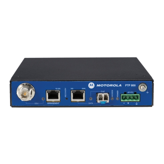
Cambium Networks PTP 800 Series User Manual (648 pages)
Brand:
Cambium Networks
| Category:
Switch
| Size: 12 MB
Table of Contents
Table of Contents
5
Important Safety Information
3
Table of Contents
5
List of Tables
23
About this User Guide
31
Contacting Cambium Networks
32
General Information
32
Version Information
32
Problems and Warranty
34
Security Advice
36
Warnings, Cautions, and Notes
37
Caring for the Environment
38
Cambium License Agreement
39
Licensing Requirements
39
Operating License
39
Chapter 1: Product Description
41
Overview
42
Key Features
42
Supported Bands and Frequencies
43
Table 1 PTP 800 Licensed Bands and Frequencies (ODU-A Platform)
43
Table 2 PTP 800 Licensed Bands and Frequencies (ODU-B Platform)
43
Table 3 PTP 800 Licensed Bands and Frequencies (IRFU Platform)
44
Typical Users and Applications
44
System Components
45
Link Types
46
Compact Modem Unit (CMU)
48
CMU Description
48
CMU Interfaces
49
Table 4 CMU Interfaces
49
Table 5 CMU LED States
51
Further Reading on the CMU
52
Outdoor Unit (ODU)
53
ODU Description
53
ODU Interfaces
54
Table 6 ODU Interfaces
56
Further Reading on the ODU
57
Indoor RF Unit (IRFU)
58
IRFU Description
58
Branching Unit
59
Transceivers
59
IRFU Availability
59
IRFU Configuration Options
60
IRFU Interfaces
65
Table 7 IRFU Transceiver Interfaces
65
Further Reading on the IRFU
66
Antennas and Couplers
67
Antennas
67
Remote Mounting Kits (Rmks)
69
Coupler Mounting Kits
70
Direct Mount Dual-Polar Antennas
72
Further Reading on Antennas and Couplers
73
Cabling and Lightning Protection
74
Cable Grounding (ODU Platforms Only)
74
CMU to Network Connections
74
Lightning Protection (ODU Platforms Only)
74
RFU to CMU Connections
74
Further Reading on Cabling and Lightning Protection
76
Wireless Operation
77
Channel Bandwidth
77
Channel Separation
77
Adaptive Coding and Modulation
78
Automatic Transmitter Power Control
78
Modulation Modes
78
Maximum Receive Power
79
Further Reading on Wireless Operation
80
Maximum Transmit Power
80
Security
80
Ethernet Bridging
82
Customer Network
82
Management Network
83
Protocol Model
86
Further Reading on Ethernet Bridging
90
System Management
91
Management Agent
91
Web Server
91
Configuration Pages
93
Installation Wizard
93
RADIUS Authentication
93
Email Alerts
94
Snmp
94
Simple Network Time Protocol (SNTP)
96
Snmpv3 Security
96
System Logging (Syslog)
99
AES License
100
Flexible Capacity Upgrades
101
Login Information
101
Recovery Mode
102
Software Upgrade
102
Further Reading on System Management
103
1+1 Hot Standby Link Protection
104
1+1 Hot Standby Overview
104
1+1 Hot Standby Link Antenna Options
105
Bridging in 1+1 Links
106
Receive Diversity
107
Further Reading on 1+1 Hot Standby
109
Fips 140-2
110
FIPS 140-2 Capability
110
FIPS 140-2 Mode
111
Further Reading on FIPS 140-2
112
Chapter 2: Planning Considerations
113
Link Planning
114
Process
114
Maximum if Cable Length
115
Site Selection
115
Wind Loading
115
Power Supply Considerations
116
PTP Linkplanner
117
Grounding and Lightning Protection
119
Standards
119
The Need for Power Surge Protection
119
Lightning Protection Zones
120
General Protection Requirements
121
Protection Requirements for a Mast or Tower Installation
123
Protection Requirements for the ODU on a High Rise Building
125
Protection Requirements for the IRFU
129
Data Network Planning
130
Management Mode
130
IP Interface
131
Priority for Management Traffic
131
Quality of Service for Bridged Ethernet Traffic
131
VLAN Membership
131
Fast Ethernet Port Shutdown
133
Security Planning
134
Planning for AES Encryption
134
Planning for SNTP Operation
134
Planning for HTTPS/TLS Operation
135
Table 8 HTTPS/TLS Security Material
135
Planning for FIPS 140-2 Operation
136
Planning for Snmpv3 Operation
137
Table 9 Permitted Character Set for Snmpv3 Passphrases
138
Table 10 Default Snmpv3 Users
139
Planning for RADIUS Operation
140
Table 11 Definition of Auth-Role Vendor-Specific Attribute
141
Planning 1+0 Links
142
Antenna, RFU and CMU Configurations for 1+0
142
Concept of a 1+0 Link
142
Network Configurations for 1+0
146
Planning 1+1 Hot Standby Links
147
Antenna, RFU and CMU Configurations for 1+1
147
Concept of a 1+1 Hot Standby Link
147
Designating Primary and Secondary Units
154
Link Planning for 1+1 Hot Standby Links
154
Network Configurations for 1+1
155
Planning for Receive Diversity
158
Table 12 Frame Size and Latency Relationship in Rx SD Links
160
Planning 2+0 Links
161
Antenna, RFU and CMU Configurations for 2+0
161
Concept of a 2+0 Link
161
Frequency Spacing in 2+0 IRFU Based Links
167
Frequency Spacing in 2+0 ODU Based Links
167
Network Configurations for 2+0
167
Table 13 Minimum Transmit/Transmit Frequency Separation at a 2+0 IRFU Link End
167
Table 14 Minimum Transmit/Receive Frequency Separation at a 2+0 IRFU Link End
168
Ordering Components
169
Ordering Cmus
169
Table 15 Optional Components for PTP 800 Cmus
169
Ordering Antennas
171
Table 16 Selecting Antennas for each Hardware Configuration
171
Table 17 Antennas: 6 Ghz Single Polarization
172
Table 18 Antennas: 6 Ghz Dual Polarization
172
Table 19 Antennas: 7 Ghz and 8 Ghz Single Polarization
173
Table 20 Antennas: 7 Ghz and 8 Ghz Dual Polarization
173
Table 21 Antennas: 11 Ghz Single Polarization
174
Table 22 Antennas: 11 Ghz Dual Polarization
174
Table 23 Antennas: 13 Ghz Single Polarization
175
Table 24 Antennas: 13 Ghz Dual Polarization
175
Table 25 Antennas: 15 Ghz Single Polarization
176
Table 26 Antennas: 15 Ghz Dual Polarization
176
Table 27 Antennas: 18 Ghz Single Polarization
177
Table 28 Antennas: 18 Ghz Dual Polarization
177
Table 29 Antennas: 23 Ghz Single Polarization
178
Table 30 Antennas: 23 Ghz Dual Polarization
178
Table 31 Antennas: 26 Ghz Single Polarization
179
Table 32 Antennas: 26 Ghz Dual Polarization
179
Table 33 Antennas: 28 Ghz Single Polarization
179
Table 34 Antennas: 28 Ghz Dual Polarization
179
Table 35 Antennas: 32 Ghz Single Polarization
180
Table 36 Antennas: 32 Ghz Dual Polarization
180
Table 37 Antennas: 38 Ghz Single Polarization
180
Table 38 Antennas: 38 Ghz Dual Polarization
180
Ordering Odus
181
Table 39 Parabolic Radomes (Optional)
181
Table 40 Odus: Lower 6 Ghz ODU-A
182
Table 41 Odus: Upper 6 Ghz ODU-A
182
Table 42 Odus: 7 Ghz ODU-A
183
Table 43 Odus: 8 Ghz ODU-A
185
Table 44 Odus: 11 Ghz ODU-B
186
Table 45 Odus: 11 Ghz ODU-A
187
Table 46 Odus: 13 Ghz ODU-A
187
Table 47 Odus: 15 Ghz ODU-A
188
Table 48 Odus: 18 Ghz ODU-B
189
Table 49 Odus: 18 Ghz ODU-A
189
Table 50 Odus: 23 Ghz ODU-B
190
Table 51 Odus: 23 Ghz ODU-A
190
Table 52 Odus: 26 Ghz ODU-A
191
Table 53 Odus: 28 Ghz ODU-A
191
Table 54 Odus: 32 Ghz ODU-A
191
Ordering if Cable, Grounding and Lpus
192
Table 55 Odus: 38 Ghz ODU-A
192
Table 56 Cable and LPU Components
193
Table 57 Inventory of the Coaxial Cable Installation Assembly Kit (WB3616)
195
Ordering Rmks and Waveguides
197
Table 58 Rmks, Waveguides and Accessories
197
Table 59 Remote Mounting Kits
198
Table 60 Flexible Waveguides
199
Ordering Coupler Mounting Kits
200
Table 61 Flex-Twist Hanger Kits Available from Cambium
200
Table 62 ODU Coupler Mounting Kits
200
Ordering Omks
202
Table 63 Orthogonal Mounting Kits (Omks)
202
Ordering Irfus and Accessories
203
Table 64 Irfus - 6 Ghz and 11 Ghz
203
Table 66 IRFU Transceivers, Fan and Covers - 6 Ghz and 11 Ghz
205
Table 67 RF Cables between Transceiver and BU - 6 Ghz and 11 Ghz
205
Table 68 IRFU Filter Assemblies - 6 Ghz and 11 Ghz
206
Table 69 IRFU Upgrade Kits - 6 Ghz and 11 Ghz
206
Table 70 Antennas and Antenna Accessories for IRFU Deployments
207
Ordering Network Connection Components
208
Table 71 Copper Network Cables and Connectors
208
Table 72 Fiber Network Cables and Connectors
208
Ordering Capacity Upgrades
209
Table 73 Single-Step Capacity Upgrades (Per Unit)
210
Table 74 Step-By-Step Capacity Upgrades (Per Unit)
210
Chapter 3: Legal Information
211
Cambium Networks End User License Agreement
212
Acceptance of this Agreement
212
Definitions
212
Grant of License
212
Conditions of Use
213
Confidentiality
214
Title and Restrictions
214
Maintenance
215
Right to Use Cambium's Name
215
Transfer
215
Updates
215
Disclaimer
216
Limitation of Liability
216
Governing Law
217
Term of License
217
U.S. Government
217
Assignment
218
Entire Agreement
218
Survival of Provisions
218
Third Party Software
218
Hardware Warranty
230
Limit of Liability
231
Chapt er 4: Reference Inform at Ion
234
CMU Specifications
234
Equipment Specifications
234
Table 75 CMU Physical Specifications
234
Table 76 CMU Environmental Specifications
234
Table 77 CMU Electrical Specifications
234
Table 78 ODU and CMU Power Consumption (ODU-A Only)
235
ODU Specifications
237
Table 80 ODU Physical Specifications
237
Table 81 ODU-A and ODU-B Environmental Specifications
237
Table 82 RSSI Voltage, Received Signal Level and Bandwidth
237
IRFU Specifications
240
Table 83 IRFU Physical Specifications
240
Table 84 IRFU Electrical Specifications
241
Table 85 IRFU Environmental Specifications
241
Table 86 IRFU EMC and Safety Compliance
241
Flexible Waveguide Specifications
242
Table 87 IRFU Transceiver Power Consumption
242
Table 88 Antenna, Transition, Waveguide and RMK Flanges
243
Coupler Mounting Kit Specifications
247
Table 89 Torque Value in Nm (Lb Ft) for each Fastener Size
247
Table 90 ODU Coupler Physical Specifications
247
Table 91 ODU Coupler Environmental Specifications
247
Table 92 ODU Coupler Return Losses and Isolation
248
Table 93 ODU Coupler Insertion Losses
248
Protection Interface Specifications
249
Table 95 Out-Of-Band Protection Cable Pin Outs
249
General Wireless Specifications
251
Table 97 General Wireless Specifications
251
Wireless Specifications
251
Table 98 ETSI Band Plan (ODU-A and ODU-B)
252
Table 100 FCC and IC Band Plan (IRFU Platforms)
253
Table 99 FCC and IC Band Plan (ODU-A and ODU-B)
253
Capacity, Transmit Power and Sensitivity
254
Table 101 NTIA Band Plan
254
Table 102 Brazil Band Plan
254
Table 103 Lower 6 Ghz FCC and Canada with 10 Mhz Bandwidth
256
Table 104 Lower 6 Ghz FCC and Canada with 30 Mhz Bandwidth
256
Table 105 Lower 6 Ghz ETSI with 29.65 Mhz Channel Separation
257
Table 106 Upper 6 Ghz FCC with 10 Mhz Bandwidth
258
Table 107 Upper 6 Ghz FCC with 30 Mhz Bandwidth
258
Table 108 Upper 6 Ghz ETSI with 7 Mhz Channel Separation
259
Table 109 Upper 6 Ghz ETSI with 14 Mhz Channel Separation
259
Table 110 Upper 6 Ghz ETSI with 30 Mhz Channel Separation
259
Table 111 Upper 6 Ghz ETSI with 40 Mhz Channel Separation
260
Table 112 Upper 6 Ghz ETSI with 60 Mhz Channel Separation
260
Table 113 6 Ghz FCC and Canada with 10 Mhz Bandwidth for IRFU
261
Table 114 6 Ghz FCC with 25 Mhz Bandwidth for IRFU
262
Table 115 6 Ghz FCC and Canada with 30 Mhz Bandwidth for IRFU
262
Table 116 Transmit Branching Unit Losses for 6 Ghz IRFU
263
Table 117 Receive Branching Unit Losses for 6 Ghz IRFU
263
Table 118 7 Ghz ETSI with 7 Mhz Channel Separation
264
Table 119 7 Ghz ETSI with 14 Mhz Channel Separation
264
Table 120 7 Ghz ETSI with 28 Mhz Channel Separation
265
Table 121 8 Ghz ETSI with 7 Mhz Channel Separation
265
Table 122 8 Ghz ETSI with 14 Mhz Channel Separation
266
Table 123 8 Ghz ETSI with 28 Mhz Channel Separation
266
Table 124 8 Ghz ETSI with 29.65 Mhz Channel Separation
266
Table 125 11 Ghz FCC and Canada with 10 Mhz Bandwidth (ODU-A)
267
Table 126 11 Ghz FCC and Canada with 10 Mhz Bandwidth (ODU-B)
267
Table 127 11 Ghz FCC and Canada with 30 Mhz Bandwidth (ODU-A)
268
Table 128 11 Ghz FCC and Canada with 30 Mhz Bandwidth (ODU-B)
268
Table 129 11 Ghz FCC and Canada with 40 Mhz Bandwidth (ODU-A)
269
Table 130 11 Ghz FCC and Canada with 40 Mhz Bandwidth (ODU-B)
269
Table 131 11 Ghz ETSI with 40 Mhz Channel Separation
270
Table 132 11 Ghz FCC and Canada with 10 Mhz Bandwidth for IRFU
271
Table 133 11 Ghz FCC and Canada with 30 Mhz Bandwidth for IRFU
272
Table 134 11 Ghz FCC and Canada with 40 Mhz Bandwidth for IRFU
272
Table 135 Transmit Branching Unit Losses for 11 Ghz IRFU
273
Table 136 Receive Branching Unit Losses for 11 Ghz IRFU
273
Table 137 13 Ghz ETSI with 7 Mhz Channel Separation
274
Table 138 13 Ghz ETSI with 14 Mhz Channel Separation
274
Table 139 13 Ghz ETSI with 28 Mhz Channel Separation
275
Table 140 15 Ghz ETSI with 7 Mhz Channel Separation
276
Table 141 15 Ghz ETSI with 14 Mhz Channel Separation
276
Table 142 15 Ghz ETSI with 28 Mhz Channel Separation
277
Table 143 15 Ghz ETSI with 56 Mhz Channel Separation
277
Table 144 18 Ghz FCC and Canada with 10 Mhz Bandwidth (ODU-A)
278
Table 145 18 Ghz FCC and Canada with 10 Mhz Bandwidth (ODU-B)
278
Table 146 18 Ghz FCC and Canada with 20 Mhz Bandwidth (ODU-A)
279
Table 147 18 Ghz FCC and Canada with 20 Mhz Bandwidth (ODU-B)
279
Table 148 18 Ghz FCC and Canada with 30 Mhz Bandwidth (ODU-A)
280
Table 149 18 Ghz FCC and Canada with 30 Mhz Bandwidth (ODU-B)
280
Table 150 18 Ghz FCC and Canada with 40 Mhz Bandwidth (ODU-A)
281
Table 151 18 Ghz FCC and Canada with 40 Mhz Bandwidth (ODU-B)
281
Table 152 18 Ghz FCC and Canada with 50 Mhz Bandwidth (ODU-A)
282
Table 153 18 Ghz FCC and Canada with 50 Mhz Bandwidth (ODU-B)
282
Table 154 18 Ghz FCC and Canada with 80 Mhz Bandwidth (ODU-B)
283
Table 155 18 Ghz ETSI with 7 Mhz Channel Separation
283
Table 156 18 Ghz ETSI with 13.75 Mhz Channel Separation
283
Table 157 18 Ghz ETSI with 27.5 Mhz Channel Separation
284
Table 158 18 Ghz ETSI with 55 Mhz Channel Separation
284
Table 159 18 Ghz Brazil with 13.75 Mhz Channel Separation
285
Table 160 18 Ghz Brazil with 27.5 Mhz Channel Separation
285
Table 161 18 Ghz Brazil with 55 Mhz Channel Separation
285
Table 162 23 Ghz FCC and Canada with 10 Mhz Bandwidth (ODU-A)
286
Table 163 23 Ghz FCC and Canada with 10 Mhz Bandwidth (ODU-B)
287
Table 164 23 Ghz FCC and Canada with 20 Mhz Bandwidth (ODU-A)
287
Table 165 23 Ghz FCC and Canada with 20 Mhz Bandwidth (ODU-B)
288
Table 166 23 Ghz FCC and Canada with 30 Mhz Bandwidth (ODU-A)
288
Table 167 23 Ghz FCC and Canada with 30 Mhz Bandwidth (ODU-B)
289
Table 168 23 Ghz FCC and Canada with 40 Mhz Bandwidth (ODU-A)
289
Table 169 23 Ghz FCC and Canada with 40 Mhz Bandwidth (ODU-B)
290
Table 170 23 Ghz FCC and Canada with 50 Mhz Bandwidth (ODU-A)
290
Table 171 23 Ghz FCC and Canada with 50 Mhz Bandwidth (ODU-B)
291
Table 172 23 Ghz ETSI with 7 Mhz Channel Separation
291
Table 173 23 Ghz ETSI with 14 Mhz Channel Separation
291
Table 174 23 Ghz ETSI with 28 Mhz Channel Separation
292
Table 175 23 Ghz ETSI with 56 Mhz Channel Separation
292
Table 176 26 Ghz FCC with 10 Mhz Bandwidth
293
Table 177 26 Ghz FCC with 20 Mhz Bandwidth
293
Table 178 26 Ghz FCC with 40 Mhz Bandwidth
294
Table 179 26 Ghz ETSI with 7 Mhz Channel Separation
294
Table 180 26 Ghz ETSI with 14 Mhz Channel Separation
294
Table 181 26 Ghz ETSI with 28 Mhz Channel Separation
295
Table 182 26 Ghz ETSI with 56 Mhz Channel Separation
295
Table 183 28 Ghz ETSI with 7 Mhz Channel Separation
296
Table 184 28 Ghz ETSI with 14 Mhz Channel Separation
296
Table 185 28 Ghz ETSI with 28 Mhz Channel Separation
297
Table 186 28 Ghz ETSI with 56 Mhz Channel Separation
297
Table 187 32 Ghz ETSI with 7 Mhz Channel Separation
298
Table 188 32 Ghz ETSI with 14 Mhz Channel Separation
298
Table 189 32 Ghz ETSI with 28 Mhz Channel Separation
299
Table 190 32 Ghz ETSI with 56 Mhz Channel Separation
299
Table 191 38 Ghz FCC and Canada with 10 Mhz Bandwidth
300
Table 192 38 Ghz FCC and Canada with 50 Mhz Bandwidth
300
Table 193 38 Ghz ETSI with 7 Mhz Channel Separation
301
Table 194 38 Ghz ETSI with 14 Mhz Channel Separation
301
Table 195 38 Ghz ETSI with 28 Mhz Channel Separation
302
Table 196 38 Ghz ETSI with 56 Mhz Channel Separation
302
Data Network Specifications
303
Ethernet Interfaces
303
Table 197 Copper Data Port Specifications
303
Table 198 Fiber Data Port Specifications
303
Table 199 Management Port Specifications
303
Ethernet Bridging
304
Table 200 Ethernet Bridging Specifications
304
Configuration and Status Messages
305
Format of Syslog Server Messages
305
Syslog Message Formats
305
Event Messages
306
Table 201 Event Messages
306
Network Management Specifications
309
Standard SNMP Mibs
309
Table 202 Standard SNMP Objects
309
Table 203 Identification of Interfaces
311
Table 204 Counters for the Wireless Interface
311
Table 205 Counters for the Data Interface
312
Table 206 Counters for the Management Interface
312
Table 207 Supported Standard Notifications
313
Electrical Safety Compliance
314
Electromagnetic Compliance
314
EMC Immunity Compliance
314
Table 208 Electrical Safety Specifications
314
Table 209 EMC Immunity Compliance Specifications
314
Compliance Testing
315
Notifications
316
ETSI Method
318
Radiation Hazard Assessment
318
Table 210 PTP 800 Minimum Separation Distances, ETSI Method
319
FCC Method
320
Table 211 PTP 800 Minimum Separation Distances, FCC Method (ODU)
321
Table 212 PTP 800 Minimum Separation Distances, FCC Method (IRFU)
321
Chapter 5: Installation
323
Preparing for Installation
324
Grounding and Lightning Protection Requirements
324
Safety Precautions During Installation
324
Selecting Installation Options
324
Preparing Inventory
325
Preparing Personnel
325
Preparing Tools
325
Table 213 Tools Required for PTP 800 Installation
325
Unit Pre-Configuration
326
Installing Antennas and Odus
327
Table 214 Selecting Antenna and ODU Installation Procedures
327
Installing a Direct Mount Antenna with One ODU
328
Installing a Remote Mount Antenna with One ODU
331
Installing a Direct Mount Antenna with Two Odus (Via Coupler)
342
Installing a Remote Mount Antenna with Two Odus (Via Coupler)
348
Installing a Direct Mount Dual-Polar Antenna with Two Odus
355
Installing the if and Ground Cables
358
Fitting an N Type Connector to an if Cable
360
Preparing if Cables
360
Connecting the ODU to the Top LPU
364
Weatherproofing an N Type Connector
367
Hoisting the Main if Cable
371
Installing and Grounding the Main if Cable
374
Making an if Cable Ground Point
376
Installing and Grounding the if Cable at Building Entry
380
Testing the ODU and if Cable
382
Recommended Pre-Power Tests
382
Test Equipment
382
Test Preparation
383
Testing Cable Loss
384
Table 215 Expected Cable Loss When ODU Is Not Connected
388
Measuring Distance to Fault
389
Installing Antennas and Irfus
392
Preparation
392
Table 216 Tools Required for IRFU Installation
392
Installing the IRFU in the Rack
393
Connecting the Flexible Waveguide to the IRFU
394
Connecting the CMU Cables to the IRFU
395
Table 217 IRFU Waveguide and Flange Specifications
395
Grounding the IRFU
396
Connecting Power to the IRFU
398
Installing the CMU
399
Maximum Operating Ambient Temperature for the CMU
399
Operation of CMU in a Restricted Access Location
399
Mounting the CMU
400
Grounding the CMU
402
Connecting the CMU to the if Cable
403
Connecting the CMU Power Supply
404
Preparing Network Connections (1+0 and 2+0 Links)
406
Installing a Copper Data Interface
407
Installing a Fiber Data Interface
408
Installing a Management Interface
409
Connecting Fiber Cables to the CMU
410
Preparing Network Connections (1+1 Hot Standby)
411
Table 218 Selecting Network Interfaces for 1+1 Hot Standby Links
411
Installing an Out-Of-Band Protection Splitter
412
Installing a Redundant Copper Interface
413
Installing a Redundant Fiber Interface
414
Installing a Fiber-Y Interface
415
Installing a Protection Cable
416
Replacing IRFU Components
417
Replacing a Transceiver
419
Table 219 Tools Required for IRFU Component Replacement
419
Replacing a Branching Unit
422
Replacing Filters
424
Replacing a Fan Assembly
425
Replacing an RF Cable
426
Table 220 RF Cable Connections (1+1 Tx MHSB / Rx SD Example)
427
Chapter 6: Configuration and Alignment
429
Preparing for Configuration and Alignment
430
Regulatory Compliance During Configuration and Alignment
430
Safety Precautions During Configuration and Alignment
430
Selecting Configuration Options
430
Task 1: Connecting to the Unit
431
Configuring the Management PC
431
Updating the ARP Table
433
Connecting to the PC and Powering up
434
Logging into the Web Interface
434
Task 2: Configuring IP and Ethernet Interfaces
436
Managing the Units During Configuration and Alignment
436
Configuring the IP Interface and Management Mode
438
Table 221 IP Interface Attributes
440
Table 222 Management Port Attributes
442
Table 223 Data Port Attributes
444
Table 224 Bridged Ethernet Traffic Attributes
446
Reconnecting to the Management PC
447
Task 3: Installing License Keys
449
Checking Licensed Capabilities
449
Table 225 Capability Summary Attributes
450
Entering a New License Key
451
Generating a New License Key
451
Starting the Full Capacity Trial
452
Task 4: Upgrading Software Version
453
Checking the Installed Software Version
453
Upgrading to a New Software Version
454
Task 5: Configuring Security
456
Configuring AES Encryption
457
Configuring AES Encryption in an Operational Link
459
Configuring HTTPS/TLS
460
Using the Security Wizard
461
Configuring Local User Accounts
470
Table 228 Password Complexity Configuration Attributes
473
Changing Own User Password
476
Table 229 Identity-Based User Accounts Attributes
476
Protecting Access to the Summary and Status Pages
477
Configuring RADIUS Authentication
478
Table 230 RADIUS Authentication Attributes
480
Task 6: Configuring Protection
481
Configuring Unprotected Links
481
Configuring 1+1 Hot Standby Links
482
Table 231 Protection Configuration Attributes
486
Upgrading an Unprotected Link to 1+1 Hot Standby
489
Task 7: Configuring Wireless Interface
491
Prerequisites for the Installation Wizard
491
Starting Installation Wizard
491
Step 1: Enter Equipment Details
493
Table 232 Step 1: Equipment Configuration Attributes
494
Step 2: Enter Details of the Radio License
497
Table 233 Step 2: Radio License Configuration Attributes
499
Step 3: Configuring Wireless Parameters
500
Table 234 Step 3: Wireless Configuration Attributes
500
Step 4: Confirming Installation Configuration
501
Step 5: Skipping Antenna Alignment
503
Step 6: Completing Configuration Without Alignment
504
Task 8: Setting up SNMP Agent
505
Configuring Snmpv3 Agent
505
Table 235 Step 1: SNMP Configuration Attributes (for Snmpv3)
506
Table 236 Step 2: SNMP MIB-II System Objects Attributes
507
Table 237 Step 3: SNMP User Policy Configuration Attributes (for Snmpv3)
509
Table 238 Step 3: SNMP User Accounts Configuration Attributes (for Snmpv3)
510
Table 239 Step 5: SNMP Trap Configuration Attributes (for Snmpv3)
511
Configuring Snmpv1/2C Agent
514
Table 240 Step 1: SNMP Configuration Attributes (for Snmpv1/2C)
514
Table 241 Step 3: SNMP Trap Configuration Attributes (for Snmpv1/2C)
516
Task 9: Configuring Alarms and Messages
518
Configuring Generation of Diagnostics Alarms
518
Configuring Generation of Email Messages
520
Table 242 Email Configuration Attributes
521
Task 10: Configuring Syslog
522
Configuring System Logging (Syslog)
522
Table 243 Syslog Configuration Attributes
523
Task 11: Configuring Remote Access
524
Configuring Web-Based Management Attributes
524
Table 244 Web-Based Management Attributes
525
Task 12: Aligning Antennas
526
Introduction to Antenna Alignment
526
Aligning Dual-Polar Antennas
527
Aligning Protected Antennas
527
Prerequisites for Alignment
527
Aligning a Pair of Antennas
528
Step 5: Starting Antenna Alignment
528
Step 6: Aligning Antennas
528
Step 7: Completing Alignment
533
Task 13: Reviewing Configuration and Performance
534
Reviewing System Configuration Attributes
534
Table 245 System Configuration Attributes
536
Comparing Actual to Predicted Performance
538
Task 14: Configuring Quality of Service
539
Configuring Quality of Service
539
Table 246 Layer 2 Control Protocols
541
Table 247 Ethernet Priority Queue Settings
541
Task 15: Connecting Link to the Network
542
Connecting to the Network
542
Setting the Real-Time Clock
543
Table 248 Manual Clock Attributes
544
Table 249 SNTP Clock Attributes
546
Saving the System Configuration
547
Configuring for FIPS 140-2 Applications
549
Prerequisites for FIPS 140-2 Configuration
549
Checking that the Unit Is in FIPS 140-2 Secure Mode
550
Configuration Procedures for FIPS 140-2
550
HTTPS Key Size Warning
551
Chapt er 7: Operat Ion
554
Accessing the Web Interface
554
Web-Based Management
554
Table 250 Procedures Performed from each Menu Option
556
Table 251 System Summary Attributes
558
Viewing the System Summary
558
Viewing the System Status
559
Table 252 RFU Status Attribute Values
562
Table 253 Transmitter Status Attribute Values
562
Table 254 Wireless Link Status Attribute Values
563
Table 255 Transmit Modulation Selection Detail Attribute Values
563
Identifying a Unit from the Web Browser Title
564
Table 256 Data Port Status Attribute Values
564
Table 257 Management Port Status Attribute Values
564
Table 258 Browser Title Attribute Variables
565
Logging out
566
Managing Alarms
567
Managing Alarms and Events
567
Managing Email Alerts
576
Managing SNMP Traps
576
Managing Event Notification Messages
583
Disabling and Enabling the Wireless Interface
584
Disabling Wireless Transmission
584
Enabling Wireless Transmission
584
Managing 1+1 Hot Standby Links
585
Viewing the Status of a 1+1 Hot Standby Link
585
Table 260 Protected Link Page Symbols and Text
586
Using the Protected Link Page
588
Forcing Protection Switches
589
Enabling and Disabling Fault Protection
595
Replacing a CMU in a 1+1 Hot Standby Link
600
Exiting FIPS 140-2 Mode
603
Managing Security
603
Zeroizing Critical Security Parameters
603
Disabling AES Encryption
604
Displaying Login Information
604
Changing AES Encryption Keys
605
Changing the Log-Out Timer
608
Checking System Statistics and Counters
609
Managing Performance
609
Table 261 System Statistics and Counters Attributes
611
Resetting System Statistics and Counters
614
Viewing Diagnostics
614
Using the Diagnostics Plotter
615
Downloading Diagnostic Data
616
Changing the Diagnostics Refresh Period
617
Maintaining the System
618
Restoring the System Configuration
619
Restoring, Upgrading and Rebooting
619
Upgrading Software
620
Rebooting
621
Upgrading Software in an Operational 1+1 Hot Standby Link
621
Checking the Recovery Version
622
Entering Recovery Mode
623
Using Recovery Mode
623
Selecting Recovery Option
624
Table 262 Recovery Options
625
Upgrading Software Image
626
Resetting IP and Ethernet Configuration to Factory Defaults
627
Erasing Configuration
628
Zeroizing Security Parameters
628
Downgrading PTP 800 Software
629
Chapter 8: Troubleshooting
631
Connecting to the Web Management Interface
632
Check the CMU Power Indicator
632
Check the DC Supply to the CMU
632
Table 263 CMU Power Indicator Checks
632
Table 264 DC Supply Checks When CMU Power Indicator Is off
632
Check the CMU Status Indicator
633
CMU out of Service
633
Table 265 CMU Status Indicator Checks
633
Check the Management Port Ethernet Connection
634
Table 266 Management Port Indicator Checks
634
Check the Copper Data Port Ethernet Connection
635
Table 267 Copper Data Port Indicator Checks
635
Check the Fiber Data Port Ethernet Connection
636
Table 268 Fiber Data Port Indicator Checks
636
Check Browser Settings
638
Table 269 Ping Response Checks
638
Installing the Link
639
Check RFU Status
639
Connect to the Web Management Interface
639
Table 270 RFU Status Checks
639
Antenna Alignment
640
Table 271 Transmitter Status Checks
640
Check Link Status
641
Check Transmit and Receive Frequencies
641
Check Waveguide and Antennas
641
Table 272 Link Status Checks
641
Check IRFU Status Leds
642
Table 273 IRFU LED Status Checks
642
Testing Protection Switchover
643
Check Protection Interface Status
643
Check that Protection Switching Is Enabled
643
Table 274 Protected Interface Status Values and Actions
643
Check the Configuration of the Active and Inactive Units
644
Check the Link Protection Cable
644
Check the Status of the Wireless Interface
644
Force a Protection Switchover
644
Glossary
645
Advertisement
Advertisement
Related Products
Cambium Networks PTP 820 Series
Cambium Networks PTP 820S Assured
Cambium Networks PTP 820C
Cambium Networks PTP 820C HP
Cambium Networks PTP 820S
Cambium Networks PTP 820E
Cambium Networks PTP 820G
Cambium Networks PTP 820 RFU-E
Cambium Networks PTP 850E
Cambium Networks PTP 820F
Cambium Networks Categories
Wireless Access Point
Network Hardware
Network Router
Switch
Wireless Router
More Cambium Networks Manuals
Login
Sign In
OR
Sign in with Facebook
Sign in with Google
Upload manual
Upload from disk
Upload from URL