
Related Manuals for HP E27m G4


Summary of Contents for HP E27m G4
- Page 1 Maintenance and Service Guide E27m G4 model SUMMARY This guide provides information about spare parts, removal and replacement of parts, diagnostic tests, problem troubleshooting, and more.
- Page 2 Devices, Inc. Bluetooth is a trademark sure to read “Important Safety Information”. owned by its proprietor and used by HP Inc. under license. NVIDIA is a trademark and/or registered trademark of NVIDIA Corporation in the U.S. and other countries.
-
Page 3: Table Of Contents
Table of Contents 1 Getting started….……………………………………………………………………………………………………………...2 Important safety information ..........................2 Important service information and precautions..................... 2 RoHS (2002/95/EC) requirements ........................3 General descriptions ............................3 Firmware updates ..............................3 Before returning the repaired product to the customer ..................3 2 Monitor features……………………………………………………………………………………………………………….4 Features ................................ -
Page 4: Getting Started
Getting started Read this chapter to learn about safety information and where to find additional HP resources. Important safety information Carefully read the cautions and notes within this document to minimize the risk of personal injury to service personnel. The cautions and notes are not exhaustive. Proper service methods are important to the safe, reliable operation of equipment. -
Page 5: Rohs (2002/95/Ec) Requirements
Level 2: Circuit board or standard parts replacement Firmware updates Firmware updates for the monitor are available at support.hp.com. If no firmware is posted, the monitor does not need a firmware update. Before returning the repaired product to the customer Perform an AC leakage current check on exposed metallic parts to be sure the product is safe to operate without the potential of electrical shock. -
Page 6: Monitor Features
Plug and Play capability, if supported by your operating system Monitor stand ● Removable stand for flexible monitor head mounting solutions ● HP Quick Release 2 device to quickly attach the monitor head to the stand with a simple click, and then remove it with the convenient sliding tab release... - Page 7 For safety and regulatory information, refer to the Product Notices provided in your documentation kit. To access the latest user guides or manuals for your product, go to http://www.hp.com/support and follow the instructions to find your product. Then select Manuals.
-
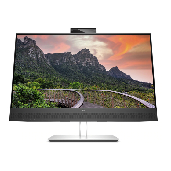
Page 8: Front Components
Front components To identify the components on the front of the monitor, use this illustration and table. Table 1-1: Front components and their descriptions Component Function Camera Allows you to video chat, record video, and record still images. NOTE: Camera functions vary depending on the camera hardware and software installed on your product. - Page 9 For additional safety information, see the Regulatory, Safety, and Environmental Notices To access this guide, type HP Documentation in the taskbar search box, and then select HP Documentation.
- Page 10 USB Type C Connects a USB Type C cable from the source device to the monitor. Serves as a single connection when docking an HP notebook. DisplayPort OUT port Connects a DisplayPort cable from the monitor to a secondary monitor.
-
Page 11: Locating The Serial Number And Product Number
The SPEC label (1) and Barcode label (2) are located on the rear of the monitor. The serial number and product number are located on a Safety label. You may need these numbers when contacting HP about the monitor model. - Page 12 For India: Bar code label Spec label...
-
Page 13: Illustrated Parts Catalog
Illustrated parts catalog To identify the monitor major components, use this illustration and table. Item Description LOGO HP 12 DECO_BEZEL Deco mylar Speaker Cover Lens SPEAKER Panel MIDDLE_FRAME Mylar... - Page 14 Power Board RUBBER Boss MAINFRAME HEAT SINK Skype key board Skype key Spring Release button K-lock plate Audio board Audio Finger OSD key board OSD key board REAR_COVER Rubber Column Base Logo-56(7121-8871) Webcam Finger Webcam Housing Webcam Hinge Webcam Scissor Webcam bracket Webcam LES USB Finger...
-
Page 15: How To Order Parts
How to order parts The HP authorized repair center can purchase the power board from HP. Power board Description HP spare part number Manufacturer part number N02580-001 PLPCLH351IQA3 PSU E27m G4 1 source N02580-002 PLPCLH511AQA1 PSU E27m G4 2 source... -
Page 16: Removal And Replacement Procedures
Removal and replacement procedures Adherence to these procedures and precautions is essential for proper service. Preparation for disassembly Use this information to properly prepare to disassemble and reassemble the monitor. 1) Read the “Important safety information” and “Important service information and precautions” sections in the “Getting started”... - Page 17 1) Remove four screw from the rear case. 2) Use your fingers to split the left and right sides apart between the middle frame and rear case. 3) Insert the scraper bar tool into the gap between the middle frame and rear case, and then rotate. The hook opens.
- Page 18 6) Remove the Audio board wire, Connector board wire and Webcam module wire from the Interface- board. 7) Disassemble the USB board from the Rear Cover (if required). 8) Remove 2 screws from the bracket. 9) Disassemble 7 screws from the board. 10) Disassemble all the boards from housing.
-
Page 19: Power Board
Before removing the power board, follow these steps: ▲ Prepare the monitor for disassembly. See Preparation for disassembly on page 14. Remove the power board: 1) The HP E24m G4 power board connector position is as follows: CN910 Warning: After unplugging the... - Page 20 The connectors are on the main board (board part number CBPCPD9H1Q1) The connectors identifiers are as follows: Connector Location HDMI CN501 DisplayPort 1 CN502 DisplayPort 2 CN503 USB Type-C CN101 RJ45 CN105 USB 3.0 CN103 MAIN BOARD CN501 CN502 CN101 CN503 CN105 CN103 This procedure includes audio connectors.
- Page 21 AUDIO BOARD CN610 This procedure includes USB3.0 connectors The connectors is on USB board (board part number USBPQAE). The connector identifiers are as follows: Connector Location USB 3.0 CN1032 USB 3.0 CN1033 USB BOARD CN1032 CN1033 Before repairing connectors, follow these steps: ▲...
-
Page 22: Audio Connector Cn610
• If connector need to replace, please insert new parts carefully because the near pin may cause short circuit by inappropriate operate. • DO NOT allow any liquid on the board. Water and moisture may cause short-circuit to the electronic components and lead to malfunctions. •... -
Page 23: Dp Connector Cn502
2) Use a hot air gun to melt the solder on the pins. 3) Lift the CN501 connector from the circuit board. 4) Place the new component on the circuit board. Be sure that it matches the footprint. 5) Solder the new component. DP connector CN502 Repair the DP connector: 1) Use a soldering iron and a de-soldering pump to remove as much solder as possible from the pin. -
Page 24: Type-C Connector Cn101
2) Use a hot air gun to melt the solder on the pins. 3) Lift the CN503 connector from the circuit board.. 4) Place the new component on the circuit board. Be sure that it matches the footprint. 5) Solder the new component. TYPE-C connector CN101 Repair the TYPE-C connector: 1) Use a soldering iron and a de-soldering pump to remove as much solder as possible from the pin. -
Page 25: Rj45 Connector Cn105
4) Place the new component on the circuit board. Be sure that it matches the footprint. 5) Solder the new component. RJ45 connector CN105 Repair the RJ45 connector: 1) Use a soldering iron and a de-soldering pump to remove as much solder as possible from the pin. 2) Lift the CN105 connector from the circuit board. - Page 26 2) Lift the CN1032&CN1033 connector from the circuit board. 3) Place the new component on the circuit board. Be sure that it matches the circuit board footprint. 4) Solder the new component.
-
Page 27: Function Test
Function test After repair, be sure to confirm that all functions are working. Table 4-1: Function test Test item Operating description Tool used HDMI test Confirm whether image displays and sound Computer or DVD player plays correctly on the monitor. DP test Confirm whether image displays and sound Computer or DVD player... - Page 28 computer’s on-board video sources. Image appears Brightness is too low. Open the OSD menu and blurred, select Brightness to adjust indistinct, or too the brightness scale as dark. needed. Check Video Monitor video cable is disconnected. Connect the appropriate Cable is video signal cable displayed on between the computer and...
-
Page 29: Index
Index components preparation for disassembly, 14 front, 6 RC removal, 14 rear, 6 rear components, 6 connector repair, 17 removal features, 4 power board, 17 firmware updates, 3 RC, 14 front components, 6 removal and replacement procedures, 14 function test, 25 returning to customer, 3 how to order parts, 12 RoHS (2002/95/EC) requirements, 3...
Need help?
Do you have a question about the E27m G4 and is the answer not in the manual?
Questions and answers