
Subscribe to Our Youtube Channel
Related Manuals for Honeywell Notifier NFN-GW-EM-3


Summary of Contents for Honeywell Notifier NFN-GW-EM-3
- Page 1 NFN-GW-EM-3 Installation and Operation Manual Embedded NFN Gateway NFN-GW-EM-3 Installation and Operation Manual Document LS10017-000NF-E Rev: D1 5/1/2019 ECN: 19-0592...
- Page 2 Fire Alarm & Emergency Communication System Limitations While a life safety system may lower insurance rates, it is not a substitute for life and property insurance! An automatic fire alarm system—typically made up of smoke Heat detectors do not sense particles of combustion and alarm detectors, heat detectors, manual pull stations, audible warning only when heat on their sensors increases at a predetermined rate devices, and a fire alarm control panel (FACP) with remote notifica-...
- Page 3 HARSH™, NIS™, and NOTI•FIRE•NET are all trademarks; and Acclimate® Plus™, eVance®, FlashScan®, FAAST Fire Alarm Aspiration Sensing Technology®, Honeywell®, Intelligent FAAST®, NOTIFIER®, ONYX®, ONYXWorks®, SWIFT®, VeriFire®, and VIEW® are all registered trademarks of Honeywell International Inc. Microsoft® and Windows® are registered trademarks of the Microsoft Corporation. Chrome™ and Google™ are trademarks of Google Inc.
- Page 4 Documentation Feedback Your feedback helps us keep our documentation up-to-date and accurate. If you have any comments or suggestions about our on-line help or manuals, please email us at FireSystems.TechPubs@honeywell.com. On-Line Help – Please include the following information: • Product name and version number (if applicable) •...
-
Page 5: Table Of Contents
Table of Contents Section 1 Product Overview ..............................7 1.1: Operation ..........................................7 1.2: Functionality .........................................7 1.3: Recommended Cybersecurity Practices ................................7 1.4: Required Software ........................................7 1.5: Environmental Requirements ....................................7 1.6: System Architecture......................................7 Figure 1.1 Direct Panel Architecture ...............................7 Figure 1.2 Single NFN Network Architecture............................8 Figure 1.3 Multiple NFN Networks Architecture............................9 1.6.1: Redundancy ......................................10 Figure 1.4 Redundant NFN-GW-EM-3s..............................10... - Page 6 Table of Contents 3.2.3: Main Menus ......................................25 Table 3.1 Main Menus ...................................25 3.2.4: Product Information....................................26 Table 3.2 Product Information................................26 3.2.5: Additional Properties ....................................27 Table 3.3 Additional Properties ................................27 3.2.6: Node List .........................................29 3.2.7: Error Log .........................................29 Table 3.4 Error Log Descriptions ................................29 3.3: Security Certificate ......................................29 Figure 3.2 Chrome Security Warning Example.............................29 3.4: Web Portal Setup ........................................30...
-
Page 7: Section 1 Product Overview
Section 1 Product Overview 1.1 Operation ® ® ™ The NFN-GW-EM-3 serves as a bridge between an ONYXWorks Workstation or ONYX FirstVision and the connected Fire Alarm Control Panels (FACPs), NFN network, or high-speed NFN network. ® The web portal feature serves as a bridge between eVance and the connected FACPs, NFN network, or high-speed NFN network. - Page 8 Product Overview System Architecture IP Network Ethernet Ethernet Workstation Workstation Ethernet NFN-GW-EM-3 HS-NCM NFN Network FACP FACP FACP Figure 1.2 Single NFN Network Architecture NFN-GW-EM-3 Installation and Operation Manual — P/N LS10017-000NF-E:D1 5/1/2019...
- Page 9 System Architecture Product Overview IP Network Ethernet Ethernet PC Gateway with Workstation Workstation Ethernet Ethernet NFN-GW-EM-3 Workstation HS-NCM NFN Network NFN Network FACP FACP FACP FACP FACP FACP Figure 1.3 Multiple NFN Networks Architecture NFN-GW-EM-3 Installation and Operation Manual — P/N LS10017-000NF-E:D1 5/1/2019...
-
Page 10: 1: Redundancy
Product Overview System Architecture 1.6.1 Redundancy A redundant gateway is a second gateway which communicates with an NFN network. If the main gateway cannot be reached, the system attempts to communicate with the network through the redundant gateway. For more information about configuring redundant gateways, refer to the ONYXWorks Workstation Installation and Operation Manual. -
Page 11: Ip Requirements
IP Requirements Product Overview 1.7 IP Requirements 1.7.1 IP Port Settings The following IP ports must be available to the NFN-GW-EM-3: Port Type Direction Purpose UDP and TCP Out DNS resolution: The optional web portal feature in the NFN-GW-EM-3 must resolve www.evanceservices.com for communications to the... -
Page 12: Agency Listings
Product Overview Agency Listings 1.8 Agency Listings 1.8.1 Standards Compliance - This product has been investigated to, and found to be in compliance with, the following standards: National Fire Protection Association NFPA72 National Fire Alarm and Signaling Code • Underwriters Laboratories •... -
Page 13: Compatible Equipment
Compatible Equipment Product Overview 1.9 Compatible Equipment The NFN-GW-EM-3 is compatible with the following equipment. Table 1.1 Compatible Equipment Type Equipment • NFS-320 • NFS2-640 Fire Panels: • NFS2-3030 • NCM-W, NCM-F Network Cards: • HS-NCM-W, HS-NCM-SF, HS-NCM-MF, HS-NCM-WSF, HS-NCM-WMF, HS-NCM-MFSF •... -
Page 14: Section 2 Installation
Section 2 Installation 2.1 Required Equipment 2.1.1 NFN-GW-EM-3 Assembly: The following components are shipped with the NFN-GW-EM-3: • NFN-GW-EM-3 Printed Circuit Board • Surge Suppressor (P/N PNET-1) • NUP-to-NUP Cable (P/N 75577) - Used to connect the NFN-GW-EM-3 board to an NCM-W or NCM-F board or supported panel. -
Page 15: Board Installation
Board Installation Installation 2.2 Board Installation The NFN-GW-EM-3 may be installed in a CAB-3 or CAB-4 cabinet as shown below. Keypad Removed Mounting Studs Board Board Bracket Slot Install bracket on 1/2” standoffs. Place the board’s Mount in 4th column of the NFS2-640 Series tab in the bracket slot and screw the board to the chassis. -
Page 16: Connections
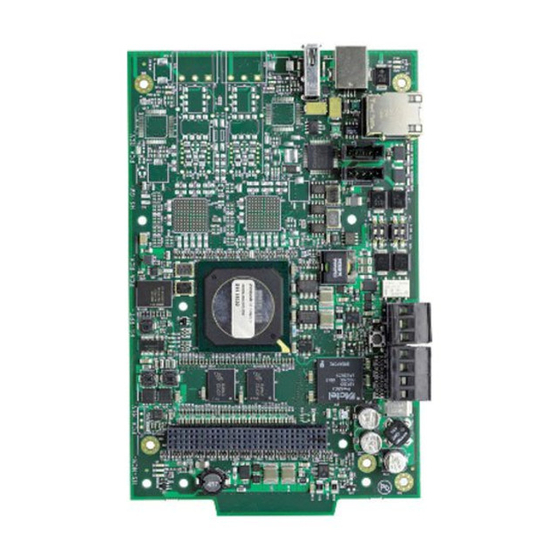
Installation Connections 2.3 Connections 2.3.1 Connecting to the NFN-GW-EM-3 USB “A” Host (J2) USB “B” Device (J1) Ethernet Connector (J3) NUP A Connector (J4) Mounting Hole (1 of 12) Not Used (J5) Trouble Relay (See 2.3.2) (TB1) 24 V Out (TB2) 24 V In Figure 2.5 NFN-GW-EM-3 Connections... - Page 17 Connections Installation (J1) (J3) LEDs (See Table Below) (J4) (J5) (TB1) (TB2) Figure 2.6 NFN-GW-EM-3 LEDs Table 2.2 LED Definitions Reference Label Description Designator ACTIVE Active/Lit indicates that WinCE is running. NUPA RX Blinks when data is received on the NUP A port (J4). PROGRAM Not Used NUPB RX...
-
Page 18: 2: Trouble Relay Connections
Installation Connections 2.3.2 Trouble Relay Connections The NFN-GW-EM-3 can be supervised by using an input module on an FACP. During normal operation (when the NFN-GW-EM-3 is not detecting an error) it activates the internal relay. When the relay is active, the input module detects the end-of-line resistor. When the NFN-GW-EM-3 detects an error, it deactivates the internal relay and posts an event to the error log (refer to 3.2.7, "Error Log"). -
Page 19: 3: Connecting To A Standard Ncm
Connections Installation 2.3.3 Connecting to a Standard NCM Connect Either Cable to Either NUP Connector on the NCM Communication from NUP A (J4) Only NFN-GW-EM-3 Out to NCM – 24V In From External Power Source to TB2 – 24 VDC Figure 2.8 Routing Power and Communication to a Standard NCM Table 2.3 Standard NCM Connections Type... -
Page 20: 4: Connecting To An Hs-Ncm
Installation Connections 2.3.4 Connecting to an HS-NCM For Communications, Connect USB A to B OR USB B to A HS-NCM NFN-GW-EM-3 Out to HS-NCM – – 24V In From External 24 VDC Power Source to TB2 Figure 2.9 Routing Power and Communication to an HS-NCM Table 2.4 HS-NCM Connections Type Connection... -
Page 21: 5: Connecting To A Fire Alarm Control Panel (Facp)
Connections Installation 2.3.5 Connecting to a Fire Alarm Control Panel (FACP) Panel is shown for illustrative purposes only. The NUP Cable Provides Both NFN-GW-EM-3 is mounted within the FACP cabinet and Power and Communication connected with the NUP connection located on the FACP. -
Page 22: System Power
Installation System Power 2.4 System Power Table 2.5 Power Requirements Power Requirement Input Voltage (Nominal) 24 VDC Input Current @ 24 VDC 125 mA 2.5 Testing and Maintenance Testing and maintenance should be performed according to the Testing and Maintenance section of NFPA-72 and CAN/ULC S536. NFN-GW-EM-3 Installation and Operation Manual —... -
Page 23: Section 3 Configuration
Section 3 Configuration 3.1 Configuration Web Page Configuration of the NFN-GW-EM-3 is via a web page running on the NFN-GW-EM-3. Supported web browsers are listed in 1.4, "Required Software". The following information applies to IP settings: • Each NFN-GW-EM-3 is shipped with a default IP address of 192.168.1.2 and a default node number of 240. •... -
Page 24: 2: Basic Configuration Tool Layout
Configuration Configuring the NFN-GW-EM-3 3.2.2 Basic Configuration Tool Layout Click for Product Click to Enter or Information (see 3.2.4) Change Text Main Menus (see 3.2.3) Click for Drop-down List Click to View Sub-items Error Log (see 3.2.7) Click to Apply Changes Navigation Tree: Additional Properties (see 3.2.5) Node List (see 3.2.6) -
Page 25: 3: Main Menus
Configuring the NFN-GW-EM-3 Configuration 3.2.3 Main Menus The following table describes the options available in the configuration tool main menus (see Figure 3.1). Table 3.1 Main Menus Menu Option Description Reboot Reboots the NFN-GW-EM-3. File History Displays a window containing a historical list of error messages. View Node Table Displays a window containing software version information for all monitored... -
Page 26: 4: Product Information
Configuration Configuring the NFN-GW-EM-3 3.2.4 Product Information The following information displays when initially opening the configuration tool. It can also be accessed by clicking the first entry in the navigation tree (see Figure 3.1). Table 3.2 Product Information Property Value Type Displays the gateway type by name. -
Page 27: 5: Additional Properties
Configuring the NFN-GW-EM-3 Configuration 3.2.5 Additional Properties The Additional Properties folder is located in the navigation tree area of the configuration tool (see Figure 3.1). After configuring the settings, click Apply in the lower right corner of the window. Table 3.3 Additional Properties Navigation Property Value... - Page 28 Configuration Configuring the NFN-GW-EM-3 Table 3.3 Additional Properties (Continued) Navigation Property Value Tree Label NFN Settings Node Settings (Continued) Node Enter the NFN node number of the NFN-GW-EM-3. (Default is 240) Panel Label Enter panel label. • Select None if Mass Notification is not used (default). Mass •...
-
Page 29: 6: Node List
Security Certificate Configuration 3.2.6 Node List The node list is located in the navigation tree area of the configuration tool screen (see Figure 3.1). Click the desired node label to view information about that node. The information displayed is dependent on the node type. Labels for off-line nodes display in red text. 3.2.7 Error Log The error log displays specific information when the NFN-GW-EM-3 detects a problem with the web portal connection. -
Page 30: Web Portal Setup
Configuration Web Portal Setup address of the gateway must be provided. The certificate is specific to the specified IP address. If the IP address is changed, a new certificate will be required. In addition, the certificates have an expiration date. Once the certificate expires, a new certificate needs to be sent to the gateway. -
Page 31: Client Monitoring
Client Monitoring Configuration 3.5 Client Monitoring The NFN-GW-EM-3 is able to monitor connected clients. When the NFN-GW-EM-3 detects a monitored client has disconnected, the NFN-GW-EM-3 deactivates the output relay. An active relay indicates that the client is operating properly. If power is disconnected from the gateway, the lack of the active relay results in a trouble on the connected monitor module. -
Page 32: Appendix A Gateway Settings
Appendix A Gateway Settings NOTE: The procedures in this appendix require the use of a USB flash memory drive. A.1 Viewing Existing IP Settings Connect the flash drive to the NFN-GW-EM-3. Reboot the gateway. A file is created that matches the configured IP address of the gateway, followed by the extension “.txt” (e.g., 192.168.1.2.txt). If the file already exists on the drive, it will be altered to match the gateway configuration. - Page 33 Manufacturer Warranties and Limitation of Liability Manufacturer Warranties. Subject to the limitations set forth herein, Manufacturer warrants that the Products manufactured by it in its Northford, Connecticut facility and sold by it to its authorized Distributors shall be free, under normal use and service, from defects in material and workmanship for a period of thirty six months (36) months from the date of manufacture (effective Jan.
- Page 34 NOTIFIER 12 Clintonville Road Northford, CT 06472-1610 USA 203-484-7161 www.notifier.com...
Need help?
Do you have a question about the Notifier NFN-GW-EM-3 and is the answer not in the manual?
Questions and answers