
Related Manuals for Honeywell NOTIFIER VESDA-HLI-GW


Summary of Contents for Honeywell NOTIFIER VESDA-HLI-GW
- Page 1 VESDA-HLI-GW Installation and Operation Manual VESDA Gateway VESDA-HLI-GW Installation and Operation Manual Document LS10023-000NF-E Rev: C3 6/1/2022 ECN: 9200...
- Page 2 Fire Alarm & Emergency Communication System Limitations While a life safety system may lower insurance rates, it is not a substitute for life and property insurance! An automatic fire alarm system—typically made up of smoke IMPORTANT! Smoke detectors must be installed in the same room detectors, heat detectors, manual pull stations, audible warning as the control panel and in rooms used by the system for the devices, and a fire alarm control panel (FACP) with remote...
-
Page 3: Installation Precautions
Microsoft Corporation. Chrome™ and Google™ are trademarks of Google Inc. © 2022 by Honeywell International Inc. All rights reserved. Unauthorized use of this document is strictly prohibited. VESDA-HLI-GW Installation and Operation Manual — P/N LS10023-000NF-E:C3 6/1/2022... -
Page 4: Software Downloads
Documentation Feedback Your feedback helps us keep our documentation up-to-date and accurate. If you have any comments or suggestions about our on-line help or manuals, please email us at FireSystems.TechPubs@honeywell.com. On-Line Help – Please include the following information: • Product name and version number (if applicable) •... -
Page 5: Table Of Contents
Table of Contents Section 1 Product Overview ..............................7 1.1: Operation ..........................................7 1.2: Functionality .........................................7 1.3: Recommended Cybersecurity Practices ................................7 1.4: Features..........................................8 1.5: Required Software ........................................8 1.6: Environmental Requirements ....................................8 1.7: System Architecture......................................9 Figure 1.1 Network Architecture with VESDA Detectors ..........................9 1.8: IP Requirements........................................10 1.8.1: IP Port Settings ......................................10 1.8.2: IP Restrictions......................................10... - Page 6 Table of Contents 3.2.7: Error Log .........................................24 Table 3.5 Error Log Label Definitions ..............................24 Table 3.6 Error Log Message Definition ..............................24 3.2.8: Zone Mapping and Control by Event ..............................25 Table 3.7 Zone Setting/Alarm State Relationships............................25 3.3: Security Certificate ......................................26 Figure 3.2 Chrome Security Warning Example............................26 Appendix A Gateway Settings............................27 A.1: Viewing Existing IP Settings .....................................27 A.2: Resetting Factory Default Values..................................27...
-
Page 7: Section 1 Product Overview
Section 1 Product Overview 1.1 Operation ™ The VESDA-HLI-GW provides a communication link between the Xtralis network and the network via VESDAnet the VHX-1420-HFS High Level Interface (HLI). This link enables event notification and control of devices on the through the network. -
Page 8: Features
Product Overview Features 1.4 Features Monitor: (NCA-2, LCD-160, and ONYXWORKS-WS) - Highest priority event is shown on annunciators. • Prealarm • Fire Alarms • Point (VESDA Detector) Disable • Each of the following trouble categorizations encompass several related troubles. Refer to Xtralis resources for additional information.: –... -
Page 9: System Architecture
System Architecture Product Overview 1.7 System Architecture The following figure is an overview of a fire network with VESDA detectors reporting events on a VESDAnet via the VESDA-HLI-GW. RS-485 VESDA Detector VESDA Detector VESDAnet Network VESDA Detector VESDA Detector VHX-1420-HFS RS-232 VESDA-HLI-GW HS-NCM... -
Page 10: Ip Requirements
Product Overview IP Requirements 1.8 IP Requirements 1.8.1 IP Port Settings The following IP ports must be available to the VESDA-HLI-GW: Port Type Direction Purpose Redirection to Port 443 Both HTTPS Communications 4016 Upgrades 1.8.2 IP Restrictions The following restrictions apply: •... -
Page 11: Compatible Equipment
Compatible Equipment Product Overview 1.10 Compatible Equipment The VESDA-HLI-GW is compatible with the following equipment. Table 1.1 Compatible Equipment Type Equipment • VESDA Lasercompact (VLC) • VESDA Laserfocus (VLF) • VESDA Laserplus (VLP) • VESDA Laserscanner (VLS) • VEP-A00-P • VEP-A00-1P •... -
Page 12: Section 2 Installation
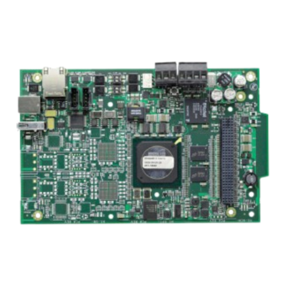
Section 2 Installation 2.1 Required Equipment 2.1.1 VESDA-HLI-GW Assembly: The following components are shipped with the VESDA-HLI-GW: • VESDA-HLI-GW printed circuit board • NUP-to-NUP Cable (P/N 7556) - Used to connect the VESDA-HLI-GW board to a standard NCM and supported panel. •... -
Page 13: Board Installation
Board Installation Installation 2.2 Board Installation The VESDA-HLI-GW may be installed in a CAB-3 or CAB-4 cabinet as shown below. Keypad Removed Mounting Studs Board Board Bracket Slot Install bracket on 1/2” standoffs. Place the board’s Mount in 4th column of the NFS2-640 Series tab in the bracket slot and screw the board to the chassis. -
Page 14: Connections
Installation Connections 2.3 Connections 2.3.1 Connecting the VESDA-HLI-GW USB “A” Host (J2) USB “B” Device (J1) Used for Configuration Only (J3) NUP A Connector (J4) Mounting Hole NUP B Connector (J5) (1 of 12) Trouble Relay (See 2.3.2) 24 V Out 24 V In Figure 2.5 VESDA-HLI-GW Connections Table 2.1 Connection Specifications... - Page 15 Connections Installation (J1) (J3) LEDs (See Table Below) (J4) (J5) (TB1) (TB2) Figure 2.6 VESDA-HLI-GW LEDs Table 2.2 LED Definitions Reference Label Description Designator ACTIVE Active/Lit indicates that WinCE is running. NUPA RX Blinks when data is received on the NUP A port (J4). PROGRAM Not Used NUPB RX...
-
Page 16: 2: Trouble Relay Connections
Installation Connections 2.3.2 Trouble Relay Connections The VESDA-HLI-GW can be supervised by using an input module on an FACP. During normal operation (when the VESDA-HLI-GW is not detecting an error) it activates the internal relay. When the relay is active, the input module detects the end-of-line resistor. When the VESDA-HLI-GW detects an error, it deactivates the internal relay and posts an event to the error log (see 3.2.7, "Error Log"). -
Page 17: 3: Connecting To A Standard Ncm
Connections Installation 2.3.3 Connecting to a Standard NCM Connect Either Cable to Either NUP Connector on the NCM Communication from NUP A (J4) Only VESDA-HLI-GW Out to NCM – 24V In From External Power Source to TB2 – 24 VDC Figure 2.8 Routing Power and Communication to a Standard NCM Table 2.3 Standard NCM Connections Type... -
Page 18: 4: Connecting To An Hs-Ncm
Installation Connections 2.3.4 Connecting to an HS-NCM For Communications, Connect USB A to B OR USB B to A HS-NCM VESDA-HLI-GW Out to HS-NCM – – 24V In From External 24 VDC Power Source to TB2 Figure 2.9 Routing Power and Communication to an HS-NCM Table 2.4 HS-NCM Connections Type Connection... -
Page 19: 5: Connecting To The Vhx-1420-Hfs
System Power Installation 2.3.5 Connecting to the VHX-1420-HFS For additional information, refer to the documentation included with the VHX-1420-HFS. NUP “B” Connector (J5) VESDA-HLI-GW DB-9 Connector VHX-1420-HFS Figure 2.10 Connecting to the VHX-1420-HFS 2.4 System Power Table 2.5 Power Requirements Power Requirement Input Voltage (Nominal) -
Page 20: Section 3 Configuration
Section 3 Configuration 3.1 Configuration Web Page Configuration of the VESDA-HLI-GW is via a web page running on the VESDA-HLI-GW. Supported web browsers are listed in 1.5, "Required Software". The following information applies to IP settings: • Each VESDA-HLI-GW is shipped with a default IP address of 192.168.1.2 and a default node number of 240. •... -
Page 21: 2: Basic Configuration Tool Layout
Configuring the VESDA-HLI-GW Configuration 3.2.2 Basic Configuration Tool Layout Click for Product Click to Enter or Click for Drop-down List Information (see 3.2.4) Change Text Main Menus (see 3.2.3) Click to View Sub-items Error Log (see 3.2.7) Navigation Tree: Additional Properties (see 3.2.5) Click to Apply Changes Node List (see 3.2.6) Figure 3.1 Basic Configuration Tool Layout... -
Page 22: 4: Product Information
Configuration Configuring the VESDA-HLI-GW 3.2.4 Product Information The following information displays when initially opening the configuration tool. It can also be accessed by clicking the first entry in the navigation tree (see Figure 3.1) Table 3.2 Product Information Property Description Type Displays the gateway type by name. -
Page 23: 6: Detector List
Configuring the VESDA-HLI-GW Configuration Table 3.3 Additional Properties (Continued) Navigation Property Description Tree Label NFN Settings Node Settings (Continued) Node Enter the NFN node number for the VESDA-HLI-GW. (Default is 0) Panel Label Enter the panel label. (Default is “Vesda Gateway”) DCC Participation This network function ensures that one location at a time is in command of the Acknowledge, System Reset, Signal Silence, and Drill functions. -
Page 24: 7: Error Log
Configuration Configuring the VESDA-HLI-GW 3.2.7 Error Log The error log displays specific information when the VESDA-HLI-GW detects a trouble condition. The following table defines the meaning of the label text. Table 3.5 Error Log Label Definitions Label Description The gateway is not reporting any errors. No Errors Found The gateway is reporting error(s). -
Page 25: 8: Zone Mapping And Control By Event
Configuring the VESDA-HLI-GW Configuration 3.2.8 Zone Mapping and Control by Event The VESDA-HLI-GW may be configured for up to 10 general zones per VESDA device. Zones 0 to 999 are supported with Zone 0 being a general alarm zone that is active if any detectors are in the FIRE1 or FIRE2 state. The zones have the following characteristics: •... -
Page 26: Security Certificate
Configuration Security Certificate 3.3 Security Certificate The VESDA-HLI-GW communicates with the browser using secure communications facilitated by a self-signed security certificate. Using the self-signed security certificate will cause the browser to display warnings similar to the following: Figure 3.2 Chrome Security Warning Example The browser warning is displayed upon each connection to the gateway. -
Page 27: Appendix A Gateway Settings
Appendix A Gateway Settings NOTE: The procedures in this appendix require the use of a USB flash memory drive. A.1 Viewing Existing IP Settings Connect the flash drive to the VESDA-HLI-GW. Reboot the gateway. A file is created that matches the configured IP address of the gateway, followed by the extension “.txt” (e.g., 192.168.1.2.txt). If the file already exists on the drive, it will be altered to match the gateway configuration. - Page 28 Gateway Settings Resetting Factory Default Values Notes VESDA-HLI-GW Installation and Operation Manual — P/N LS10023-000NF-E:C3 6/1/2022...
-
Page 29: Manufacturer Warranties And Limitation Of Liability
Manufacturer Warranties and Limitation of Liability Manufacturer Warranties. Subject to the limitations set forth herein, Manufacturer warrants that the Products manufactured by it in its Northford, Connecticut facility and sold by it to its authorized Distributors shall be free, under normal use and service, from defects in material and workmanship for a period of thirty six months (36) months from the date of manufacture (effective Jan. - Page 30 NOTIFIER 12 Clintonville Road Northford, CT 06472-1610 USA 203-484-7161 www.notifier.com...
Need help?
Do you have a question about the NOTIFIER VESDA-HLI-GW and is the answer not in the manual?
Questions and answers