Advertisement
Quick Links
Advertisement

Subscribe to Our Youtube Channel
Related Manuals for EDLUND 270


Summary of Contents for EDLUND 270
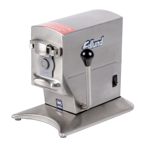
- Page 1 SERVICE MANUAL- M131 REVA MODEL 270 ELECTRIC CAN OPENER...
- Page 2 M131 Repair and Service Guidelines When a Model 270 electric can opener is returned to the factory for warranty repair, repair or for any other service issues, the following procedure will be used: Read the Quality Improvement Report that accompanies the product to determine what problems or complaints that the customer has listed.
- Page 3 M131 Model 270 Can Opener Assembly Procedures The Model 270 and Model 270C can openers will be assembled according to the following procedure. Model 270 & Model 270C Gear Plate Assembly (A272/A285 & A276) 1. Assemble the front and rear gear plate assemblies (A277) & (A276) by pressing the flanged bushing and straight bushing into the respective bushing holes.
- Page 4 M131 Model 270 & Model 270C Motor and Gear \box Assemblies (A272/A285) 1. Install the thrust washer (W093) and the output gear assembly (A278) into the front gear plate (A277). Install the second gear and pinion (A573) and the first gear and pinion (A572) into the front gear assembly.
- Page 5 M131 Frame Assembly (A283/) (Fig. 8) 1. Assemble the lever assembly (A280) onto the bottom of the motor and gearbox assembly (A272/A285) using clevis pin (P002) and cotter pin (P010). 2. Assembly one-rod retainer (R093) into the bottom of the frame assembly (A282) using two screws (S085) and washers (W023) and Loctite 242.
- Page 6 Replace the frame assembly and try latching the shield again. Repeat shimming procedure until the shield will lock in place. 4. For Model 270, place a nut (N019) on screw (S050) and install into threaded hole in stop in throat of housing. This will be adjusted later. (See Fig. 1) 5.
- Page 7 17. The base can now be installed. Place gasket plate (P244) and gasket (G047) onto the bottom of the housing assembly and install the base. For Model 270, install base assembly (A274) and secure with four screws (S071) and washers (W018). Plug the holes on the bottom of the base using plugs (P165).
- Page 8 M131 270 MAIN - 115 VOLT...
- Page 9 M131 270 – 115 VOLT CE...
- Page 10 M131 270 – 230 VOLT...
- Page 11 M131...
- Page 12 M131 18. Table clamp of Model 270C can be assembled by first installing the top bearing (B255) and bottom bearing (B258) and secure using two screws (S364) each. Slide the housing and base assembly (A294) into the table clamp. Install two plungers (P297) and two bearings (P313) into the two screw holes in the table clamp and screw in until the housing assembly will not descend faster than one inch per second.
-
Page 13: Troubleshooting Guide
M131 TROUBLE SHOOTING GUIDE Problem Cause Correction I. Can opener will not 1. Cordset not plugged into outlet. 1. Plug cordset into grounded outlet with same voltage as start. listed on rating label located on back of opener. 2. Circuit breaker tripped (CSA & 230 volt models). 2. Reset breaker, if breaker continues to trip replace breaker. - Page 14 M131 FINAL INSPECTION INSTRUCTION MODEL 270 COPY OF DOC: EC1062B 1.0 PURPOSE and SCOPE To provide a uniform and consistent method for acceptance/rejection of finished product. 2.0 INSTRUCTION 2.1 GROUND CONTINUITY/DIELECTRIC TEST The ground continuity test is performed using one of the following:...
Need help?
Do you have a question about the 270 and is the answer not in the manual?
Questions and answers