Advertisement
Quick Links
STC 160 Head-End Station
RF output collector 8 to 1
Notes on the Assembly Instructions.
As well as this supplementary Assembly
Instructions, the Assembly Instructions for the
head-end station apply.
GSS
Grundig SAT Systems GmbH
Beuthener Strasse 43
D-90471 Nuremberg
Phone:
+49 (0) 911 / 703 8877
Fax:
+49 (0) 911 / 703 9210
Email:
info@gss.de
Internet:
www.gss.de/en
HOC 168
Advertisement

Related Manuals for GSS HOC 168


Summary of Contents for GSS HOC 168
- Page 1 STC 160 Head-End Station RF output collector 8 to 1 HOC 168 Notes on the Assembly Instructions. As well as this supplementary Assembly Instructions, the Assembly Instructions for the head-end station apply. Phone: +49 (0) 911 / 703 8877 Grundig SAT Systems GmbH...
- Page 2 Meaning of the symbols used ............... 4 Technical data..................4 Description ..................4 3 Overview ......................5 4 Installing the RF output collector ................. 6 5 Setting the output level ..................7 6 Final procedures ....................8 - 2 - HOC 168...
- Page 3 2.1 s C o p e d e l i v e ry 1 RF output collectorHOC 168 1 Brief Assembly Instructions - 3 - HOC 168...
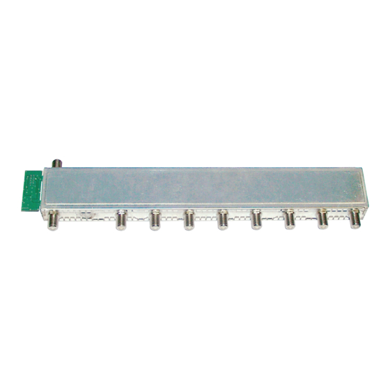
- Page 4 2.4 d es C r i p t i o n The active RF output collector HOC 168 has 8 RF inputs, one RF output and one RF test output (-20 dB). The RF output collector collects the output signals of the modules´...
- Page 5 Fig. 1 Output Connector block Test output (-20 dB) Inputs - 5 - HOC 168...
- Page 6 (knock-outs) in the rear panel of the head-end station and tighten it. • Mount the RF output collector HOC 168 to the position in the head-end sta- tion according to fig. 4. • Fasten the outer sockets of the RF output collector (Fig.
- Page 7 “Select module / channel strip” – “SETUP BE160”. • By pressing the button, you will be returned to the menu item “Select module / channel strip” – “SETUP BE160” without saving the programmed data. - 7 - HOC 168...
- Page 8 • Push the base plate in direction of the arrow and lock it with the locking screw • Tighten the fastening screws • Tighten the nuts of retrofitted F terminals if applicable. • Mount the front cover (see STC 160 assembly instructions). - 8 - HOC 168...
- Page 9 CE - Declaration of Conformity Alterations reserved. Technical data E. & O.E. © by GSS GmbH 28062013...
Need help?
Do you have a question about the HOC 168 and is the answer not in the manual?
Questions and answers