
Subscribe to Our Youtube Channel
Related Manuals for Moog Tritech Seanet SCU v5


Summary of Contents for Moog Tritech Seanet SCU v5
- Page 1 Seanet SCU v5 Seanet SCU v5 Product Manual 0581-SOM-00002, Issue: 05 0581-SOM-00002, Issue: 05 © Tritech International Ltd.
- Page 2 Seanet SCU v5 © Tritech International Ltd The copyright in this document is the property of Tritech International Ltd. The document is supplied by Tritech International Ltd on the understanding that it may not be copied, used, or disclosed to others except as authorised in writing by Tritech International Ltd. Tritech International Ltd reserves the right to change, modify and update designs and specifications as part of their ongoing product development programme.
-
Page 3: Table Of Contents
Seanet SCU v5 Table of Contents Help & Support ......................4 Warning Symbols ......................5 1. Introduction ......................6 2. Specification ......................7 2.1. Dimensions ....................7 2.2. Computer and Electrical ................8 2.3. Physical ....................... 8 2.4. SCUv5 Front Panel ..................9 2.5. -
Page 4: Help & Support
Seanet SCU v5 Help & Support First please read this manual thoroughly (particularly the Troubleshooting section, if present). If a warranty is applicable, further details can be found in the Warranty Statement, 0080- STF-00139, available upon request. Tritech International Ltd can be contacted as follows: Mail Tritech International Ltd Peregrine Road... -
Page 5: Warning Symbols
Seanet SCU v5 Warning Symbols Throughout this manual the following symbols may be used where applicable to denote any particular hazards or areas which should be given special attention: Note This symbol highlights anything which would be of particular interest to the reader or provides extra information outside of the current topic. -
Page 6: Introduction
Seanet SCU v5 1. Introduction The Seanet Surface Control Unit SCU (v5) incorporates the very latest in electronics and PC technology including readers for memory cards and a built-in factory restore mode. The latest v5 model of the SCU has again been designed with reliability and robustness in mind. The SCU is housed in a rugged 3U rack mount chassis and incorporates a front panel Remote Access Terminal (RAT) which enables all functions to be controlled by a combination of pointer and function button operations. -
Page 7: Specification
Seanet SCU v5 2. Specification 2.1. Dimensions All dimensions are in mm. Not to scale. 465.9 All dimensions are in mm. Not to scale. 0581-SOM-00002, Issue: 05 © Tritech International Ltd. -
Page 8: Computer And Electrical
Specification Seanet SCU v5 2.2. Computer and Electrical Item Details Processor Intel™ Dual Core (or better) Operating System Microsoft Windows® Embedded Primary Control PS/2 Remote Access Terminal (RAT) Video Output SVGA, XGA, SXGA, and Display Port HDMI and DVI available via Display Port adaptors ARCNET Link 1 x 156kbit·s (1200m) or 78kbit·s... -
Page 9: Scuv5 Front Panel
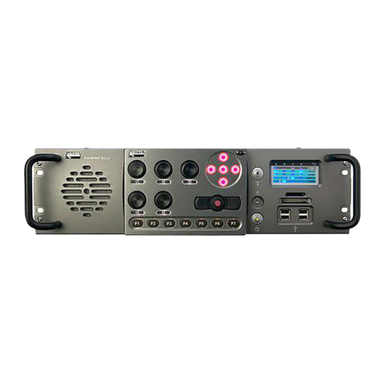
Specification Seanet SCU v5 2.4. SCUv5 Front Panel 1. The RAT can be de-coupled from the main unit completely or operated from an RS232 extension cable. The function of the RAT controls depend on which subsea sensors are fitted, and the user should refer to the appropriate section of each product manual for full details. -
Page 10: Major Differences Between Scuv4 And Scuv5
Specification Seanet SCU v5 Note The exact rear panel layout of the SCUv5 is subject to change and may not be identical to the layout shown above. For detailed pin-out diagrams and wiring options for the DE-9 and DA-15 connectors refer to Appendix A, Data and Control Ports and Appendix B, SCUv5 Communications Setup. - Page 11 Specification Seanet SCU v5 motherboard it is recommended that this port is not used to connect sensor equipment. Contact Tritech International Ltd with details of your SCU if more information or assistance is required. 0581-SOM-00002, Issue: 05 © Tritech International Ltd.
-
Page 12: Installation
Seanet SCU v5 3. Installation The Seanet SCU (v5) should be carefully removed from its transit case and checked to see that the control unit is undamaged. The unit may be inverted to check for any parts that may have been loosened during transit. If so, remove the unit cover and investigate further. The unit should be firmly mounted in a clean dry installation such as a rack system. -
Page 13: Communication Configuration
Installation Seanet SCU v5 3.2. Communication Configuration Fitted inside the SCU, located at the front panel, is the SCUv5 Main Board. This is a multi- purpose board that houses the bulk of the circuitry from the superseded AIF PCB. This includes the ARCNET interface, for communications with the subsea sensor heads, and the RAT interface. - Page 14 Installation Seanet SCU v5 Use with Serial Devices The SCU is installed with four DE-9 ports on the rear panel for use with serial communications. These ports can be configured for different standards and for survey data output ports to a data logger or as ports where Tritech International Ltd or other 3rd party sensors/devices can be connected.
-
Page 15: Operation
Seanet SCU v5 4. Operation Once a system has been installed in conjunction with the relevant sections of this manual and any relevant sensor manuals, it can be tested in air by powering up the system and observing that communications with the subsea device(s) is established. Caution The power should be turned off before making a connection between the sonar head and surface controller (SCU or SeaHub). -
Page 16: System Software Configuration
Seanet SCU v5 5. System Software Configuration Your system will be delivered with Microsoft Windows® Embedded and Seanet System Software pre-installed. A complete image of the Microsoft Windows® Embedded Operating System is provided on an internal flash memory device. This is independent from the primary C:\ partition where the system software is installed to. -
Page 17: Full Disk Re-Installation Using Boot Recovery
System Software Configuration Seanet SCU v5 5.3. Full Disk Re-Installation using Boot Recovery If any part of the Microsoft Windows® operating system becomes corrupt and requires re- installing, the original factory configuration can be restored from a backup image of the primary disk that is retained on internal flash memory. -
Page 18: Maintenance
Seanet SCU v5 6. Maintenance There are few user-serviceable parts inside the Seanet SCU (v5) that can be checked and/ or replaced. Firstly, it is recommended that the unit be used in a clean, well ventilated and dust-free environment. Also, operating in extreme temperature and humidity should be avoided if possible. -
Page 19: Data And Control Ports
Seanet SCU v5 Appendix A. Data and Control Ports Waterblock Pin-out Diagram MAIN port AUX port Cable colour RS232 TX RS232 RX ARCNET A ARCNET A Yellow RS485 A RS485 A RS232 RX RS232 TX ARCNET B ARCNET B Blue RS485 B RS485 B +DC Power... - Page 20 Data and Control Ports Seanet SCU v5 The COMMS row of LEDs are bi-colour, with Red - Receive; Green - Transmit The remaining LEDs are Blue, indicating the communications protocol which has been software selected for a particular port. If working in reduced lighting conditions, the overall brightness of the status indicators may be controlled through the “Seanet Setup”...
- Page 21 Data and Control Ports Seanet SCU v5 When used in RS-232 mode, the pin out of this port is wired in the same way as a PC serial “COM” port (i.e. using DTE signal directions), and compatible with any standard RS-232 peripherals and cabling.
- Page 22 Data and Control Ports Seanet SCU v5 ARCNET Port DA-15 female connector, providing access to: • Isolated +12V and +5V supplies. • Isolated and protected TTL ARCNET connections (LAN PULSE1, LAN PULSE2, LAN EN and LAN RX). • Isolated and protected differential ARCNET connections (LAN A, LAN B). •...
- Page 23 Data and Control Ports Seanet SCU v5 • RAT RS-485 and PS2 data signals are not isolated, and are with respect to the internal power supplies “+5V” and “GROUND”. • An internal 150ohm termination resistor is fitted across the RS-485 input signals (pins 3 and 4).
-
Page 24: Scuv5 Communications Setup
Seanet SCU v5 Appendix B. SCUv5 Communications Setup There is no AIF card inside the V5 Seanet SCU, in its place is the V5 Main Board. The Main Board provides 4 Serial Ports A,B,C,D which can be configured to RS232, RS485 or RS422. These are available on separate 9 pin D-type connectors In addition to this the Main Board feeds a 15 pin D-type connector which has the same pinouts as the 15D connector fitted to the AIF card on earlier SCU models. - Page 25 SCUv5 Communications Setup Seanet SCU v5 Tritech DA-15 Connector Connector ARCNET A ARCNET B (see note) (see note) Tritech 6-pin connector ARCNET A SCU DA-15 female connector ARCNET B nc = not connected Note Power will need to be supplied to the sonar head through pin 3 (for example 24V DC supply for a SeaKing) and pin 4 (0V ground) of the Tritech connector - the ARCNET port will not be able to supply this power and a suitable external source should be used.
- Page 26 SCUv5 Communications Setup Seanet SCU v5 Junction Box or Split AIF with RS232 Connection to the SCU should be made through the DA-15 connector. Connection Connection ARCNET Ground RS232 Rx RS232 Tx SCU DA-15 female connector nc = not connected Note In DA-15 can operate in RS232 mode (this type of operation is fixed during manufacture of the unit and cannot subsequently be changed).
- Page 27 SCUv5 Communications Setup Seanet SCU v5 Single SeaKing Sensor in RS232 The V5 SCU can support direct connection of a single node to a dedicated RS232 port. Connection can be made through the DA-15 connector (if it is wired for RS232 communications) or through one of the standard DE-9 ports, such as PORT A shown above.
- Page 28 SCUv5 Communications Setup Seanet SCU v5 SeaKing Sensors Through TTL to ARCNET Modem This is only applicable to systems operating with the Tritech International Ltd TTL to ARCNET interface PCB or alternative such as the Subsea 7 “Eagle Eye” PCB. Connection to the SCU should be made through the DA-15 connector, wired as below.
-
Page 29: Arcnet Termination
Seanet SCU v5 Appendix C. ARCNET Termination Depending on the cable length the ARCNET communication link requires a termination resistor to be installed at each end of the umbilical cable. Normally this is supplied fitted within the ARCNET cable DA-15 or within the SCU/SeaHub at the surface and is left for the user to fit at the sub-sea end in a convenient junction box or by use of a special waterblock. - Page 30 Seanet SCU v5 Appendix D. Setting the computer IP address in Windows® 7 or Windows® 10 The following instructions apply to a computer running Windows® 7 or Windows® 10, though the sequence for other operating systems will be similar. All screenshots are from a Windows®...
-
Page 31: Setting The Computer Ip Address In Windows® 7 Or Windows® 10
Setting the computer IP address in Windows® 7 or Windows® 10 Seanet SCU v5 A list of attached network devices should now present itself. Find the one which the Gemini head is to be connected to and double-click on it. The Local Area Connection Properties dialog should be displayed. -
Page 32: Glossary
Seanet SCU v5 Glossary Originally "Acoustic Interface" but also used to refer to "ARCNET Interface" in which case it can refer to either the interface port on a SeaHub or SCU or to the expansion card available for installation into a computer. - Page 33 Glossary Seanet SCU v5 Surface Control Unit - a specially manufactured computer which is rack mountable and capable of processing the data from the sonar equipment running either Windows® XP Embedded or Windows® 7 and Seanet Pro or Gemini software. SeaHub An alternative to using a Seanet SCU, this device connects to a laptop or PC via USB interface, essentially this takes the signal from the sonar...
Need help?
Do you have a question about the Tritech Seanet SCU v5 and is the answer not in the manual?
Questions and answers