Table of Contents
Advertisement
Quick Links
QUICK GUIDE
AIR
CONDITIONER
Please read this installation manual completely before installing the product.
Installation work must be performed in accordance with the national wiring standards by
authorized personnel only.
Please retain this installation manual for future reference after reading it thoroughly.
PDI (PDI Standard)
PPWRDB000
Original instructions
[Representative] LG Electronics Inc. EU Representative : LG Electronics European Shared Service Center B.V.
Krijgsman 1, 1186 DM Amstelveen, The Netherlands
[Manufacturer] LG Electronics Inc. Changwon 2nd factory 84, Wanam-ro, Seongsan-gu, Changwon-si,
Gyeongsangnam-do, KOREA
For more information, Refer to the CD or LG Web site (www.lg.com).
MFL69157007
Rev.00_092520
Copyright © 2015 - 2020 LG Electronics Inc. All Rights Reserved.
www.lg.com
Advertisement
Table of Contents

Related Manuals for LG PDI PPWRDB000


Summary of Contents for LG PDI PPWRDB000
- Page 1 PDI (PDI Standard) PPWRDB000 Original instructions [Representative] LG Electronics Inc. EU Representative : LG Electronics European Shared Service Center B.V. Krijgsman 1, 1186 DM Amstelveen, The Netherlands [Manufacturer] LG Electronics Inc. Changwon 2nd factory 84, Wanam-ro, Seongsan-gu, Changwon-si, Gyeongsangnam-do, KOREA For more information, Refer to the CD or LG Web site (www.lg.com).
- Page 2 IMPORTANT SAFETY INSTRUCTIONS IMPORTANT SAFETY INSTRUCTIONS (Only Australia) READ ALL INSTRUCTIONS BEFORE USING THE APPLIANCE. Always comply with the following precautions to avoid dangerous situations and ensure peak performance of your product. • This appliance is not intended for use by persons (including children) with reduced physical, sensory or mental capabilities, or lack of experience and knowledge, unless they have been given supervision or instruction concerning use of...
- Page 3 SAFETY PRECAUTIONS (For global) • This product must be installed by an installation professional from an LG authorized service center. • Any issues stemming from an installation by an unauthorized person is the responsibility of the user and will not be covered by warranty.
- Page 4 SAFETY PRECAUTIONS you purchased the product, or a service center. - Installation of the product by an unauthorized person may result in fire, electric shock, explosion, injury, or a malfunctioning of the product. • For electrical work, please have an electrician do the work based on the installation manual and specified circuit diagram.
- Page 5 SAFETY PRECAUTIONS - Using an unauthorized non-standard cord may result in a fire or electric shock. • Do not use a heat device near the power cord. - It may cause a fire or electric shock. • Ensure that water never gets into the product. - It can result in an electric shock, or the product may malfunction.
- Page 6 SAFETY PRECAUTIONS • If the product sounds or smells different, stop using the product. - It may cause a fire or electric shock. • Do not place a heavy object on the product. - The product may malfunction. • Do not spray water on the product, or clean it with a water-soaked cloth.
- Page 7 SAFETY PRECAUTIONS • Do not touch the panel using a pointy or sharp object. - It can result in an electric shock, or the product may malfunction. • Do not let the product come into contact with a metal substance. - The product may malfunction.
- Page 8 SAFETY PRECAUTIONS CAUTION Changes or modifications not expressly approved by the manufacturer responsible for compliance could void the user’s authority to operate the equipment. Disposal of your old appliance 1 When this crossed-out wheeled bin symbol is attached to a product it means the product is covered by the European Directive 2002/96/EC.
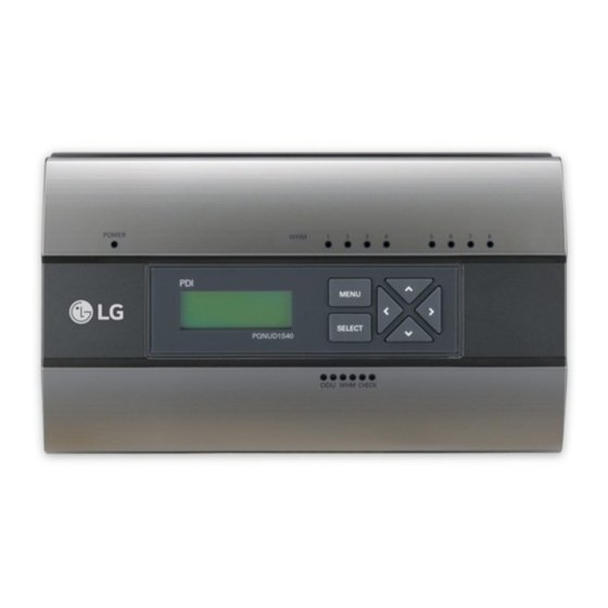
- Page 9 COMPONENTS COMPONENTS POWER MENU SELECT PPWRDB000 WHM CHECK 120 mm 270 mm Manual Power supply Power distribution indicator POWER ODU WHM CHECK Front cover Screw 1 core Item Specification Protection class IP20...
-
Page 10: Name Of Each Part
NAME OF EACH PART NAME OF EACH PART POWER Front cover ODU WHM CHECK LED display POWER Menu button MENU LCD display SELECT PPWRDB000 SELECT button WHM CHECK LED display Navigation button Power supply ① Front cover ⑤ SELECT button Use for initial setting ②... -
Page 11: Installation Method
INSTALLATION METHOD INSTALLATION METHOD Diagram of overall product configuration When interlocked to pulse type wattmeter • Interlocked Operation with Central Controller (interlocked to EHP product) Pulse signal Wattmeter Pulse signal Power In 3 phase 4 wire 380-415 V 3N~, POWER 50/60 Hz Power In MENU... - Page 12 INSTALLATION METHOD • When interlocked to GHP product - When linked with the GHP product, the central controller is linked only possible model of ACS IV series or later. Pulse signal(Power) Pulse signal(Gas) Wattmeter Power In 3 phase 4 wire 380-415 V 3N~, POWER 50/60 Hz...
-
Page 13: How To Wire The Product (When Ehp Product Is Connected)
INSTALLATION METHOD How to wire the product (when EHP product is connected) Wiring Power Indicator Wiring Power Supply Connection of pulse type wattmeter (Port 1 ~ 2) POWER 220-240 V~ power cable connection MENU terminal SELECT Grounding cable PPWRDB000 220-240 V~ connection terminal WHM CHECK... - Page 14 INSTALLATION METHOD Wiring • Separate the power supply case. • Loosen the clamp fixating the power supply. • Connect the 220-240 V~ power cable to the black and grounding terminal. • Connect the 24 V~ power cable to the yellow terminal. •...
- Page 15 INSTALLATION METHOD Connect the wattmeter and Connection of wattmeter, gas meter and communication cable (EHP products) communication cable (GHP products) When connecting the pulse-type When connecting the pulse-type wattmeter wattmeter / gas meter • Independent Operation of Power Indicator (interlocked to EHP product) Pulse type Pulse type wattmeter...
-
Page 16: Setting And Using Method
SETTING AND USING METHOD SETTING AND USING METHOD Setting up detailed functions (EHP products) Flowchart for how to set up functions (EHP products) While EHP product is selected, set the detailed functions of the power indicator with reference to the flowchart below E L E C T R I C P O W E R D I S T R I B U T O R... - Page 17 SETTING AND USING METHOD CAUTION • Power indicator setting only can be changed during the 20 minutes after turning on the power. 20 minutes later, if you need to change settings, turn the power indicator on again. C T & P U L S E R A T I O S E T C T : 0 0 0 0 0...
-
Page 18: Setting Detailed Functions (Ghp Products)
SETTING AND USING METHOD Setting detailed functions (GHP products) Function Setting Method Flowchart (GHP products) While GHP product is selected, set the detailed functions of the power indicator with reference to the following flowchart. ‘MENU’ button + ‘SELECT’ button C O N N E C T I O N : M A S T E R C O N N E C T I O N T Y P E... - Page 19 SETTING AND USING METHOD CAUTION • Power indicator setting only can be changed during the 20 minutes after turning on the power. 20 minutes later, if you need to change settings, turn the power indicator on again. C T & P U L S E R A T I O S E T C T : 0 0 0 0 0...
- Page 20 SETTING AND USING METHOD • If entering the setting screen for the first time. - After turning power on, press the ‘MENU’ button and the ‘SELECT’ button at the same time and the screen will change to the screen where you can select the product connection type.
- Page 21 ver. 1.0.4...
Need help?
Do you have a question about the PDI PPWRDB000 and is the answer not in the manual?
Questions and answers