Table of Contents
Advertisement
Quick Links
TM
FMS-cradleGUARD
Operating Manual and Installation Instructions
Wireless Signal Transmission
from Cradle to Control Station
Document Version
2.10
Published / Author
07/2019 / NS
Diese Bedienungsanleitung ist auch in Deutsch erhältlich.
Bitte nehmen Sie mit der nächstgelegenen FMS Niederlassung Kontakt auf.
© by FMS Force Measuring Systems AG, CH-8154 Oberglatt – All rights reserved.
Advertisement
Table of Contents

Related Manuals for FMS FMS-cradleGUARD

Summary of Contents for FMS FMS-cradleGUARD
- Page 1 Cradle to Control Station Document Version 2.10 Published / Author 07/2019 / NS Diese Bedienungsanleitung ist auch in Deutsch erhältlich. Bitte nehmen Sie mit der nächstgelegenen FMS Niederlassung Kontakt auf. © by FMS Force Measuring Systems AG, CH-8154 Oberglatt – All rights reserved.
-
Page 2: Table Of Contents
As-delivered Condition ..........................7 Preparation ..............................7 Installation of the FMS-cradleGUARD.T Transmission Module ..............7 Electrical Connection of the FMS-cradleGUARD.T Transmission Module ..........8 4.4.1 Connection of Sensors and Switches ....................10 Electrical Connection of the FMS-cradleGUARD.R Receiver Module ............12 DISPLAY AND OPERATION .......................... -
Page 3: Safety Information
If the battery cover is not secured correctly, it can be ejected in the case of rotating machines. Tighten the screws of the cover sufficiently. Changes or modification to this device that have not been expressly approved by FMS AG, will result in the approval for operation of this device being voided. 24.07.2019... - Page 4 FMS-cradleGUARD Operating Manual and Installation Instructions The function of this system is only ensured with the components in the specified layout to one another. Otherwise, severe malfunctions may occur. Thus, the installation information on the following pages must be followed.
-
Page 5: Product Information
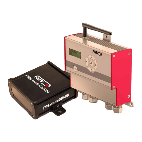
3.1 Functional Description The FMS-cradleGUARD consists of two different system components. A transmission module (FMS-cradleGUARD.T) per cradle contains terminal blocks for up to 3 sensors and the radio module. The radio frequencies can be clearly separated and ensure operational safety. The receiver module (FMS-cradleGUARD.R) outside of the machine receives the signals of the... -
Page 6: Scope Of Supply
Sensors (including cables), installation material; installation and start-up: our experts will assist you upon request Accessories: 24 VDC power supply for FMS-cradleGUARD.R receiver module, patch cable for the connection of receiver module and (e.g.) laptop for configuration via web interface. 24.07.2019... -
Page 7: Installation
The components may not be subjected to loads outside of the specified values during installation and operation later. The fastening points for supporting the components must be designed correctly. Pay attention to proper installation of the FMS- cradleGUARD.T transmission modules on the machine. The sensors must be connected electrically correctly. -
Page 8: Electrical Connection Of The Fms-Cradleguard.t Transmission Module
We recommend a centered installation of the receiver modules on the cradle to avoid this effect. 4.4 Electrical Connection of the FMS-cradleGUARD.T Transmission Module We recommend a cable with 3 x 0.5 mm for the sensor connection. The cables must be routed separately from power cables. - Page 9 FMS-cradleGUARD Operating Manual and Installation Instructions Figure 3: FMS-cradleGUARD.T Terminal Designation and Connection FMS_cradleGUARD_BA_Manual.ai Designation of sensors You can modify the below stated names (Pintle,…) of the sensors via the web browser. FMS-cradleGUARD.R Item Description 1 to 3 Sensor 1 – PINTLE LEFT (pintle lock left)
-
Page 10: Connection Of Sensors And Switches
Dip switch for channel assignment (do not change!) Dip switch for setting the ID (do not change!) Table 3: Terminal Block for FMS-cradleGUARD.T Sensors Do not change the Dip switches! Changing the Dip switches will result in the loss of the radio connection. - Page 11 FMS-cradleGUARD Operating Manual and Installation Instructions Figure 4: Sensors and Switches FMS_cradleGUARD_BA_Manual.ai 24.07.2019...
-
Page 12: Electrical Connection Of The Fms-Cradleguard.r Receiver Module
FMS-cradleGUARD Operating Manual and Installation Instructions 4.5 Electrical Connection of the FMS-cradleGUARD.R Receiver Module First, remove the cover from the front side of the component for the connection. The cover is secured with 4 countersunk-head screws. We recommend a 3 x 0.5 mm cable for the power supply. -
Page 13: Display And Operation
FMS-cradleGUARD Operating Manual and Installation Instructions 5 Display and Operation Figure 6: Control Panel and Display FMS_cradleGUARD_BA_Manual.ai FMS-cradleGUARD.R Item Description Antenna Upper fastening lug Display 24.07.2019... -
Page 14: Configuration On The Device
FMS-cradleGUARD Operating Manual and Installation Instructions FMS-cradleGUARD.R Item Description Navigation keys Left – Scroll parameter list to the left Right – Scroll parameter list to the right Up – Increase parameter value Down – Decrease parameter value Enter key Select parameter, confirmation 6;... - Page 15 FMS-cradleGUARD Operating Manual and Installation Instructions System Parameters Parameter Description IP address The IP address must be entered in 4 blocks. Min. Max. Default value 192.168.000.090 Subnet The address must be entered in 4 blocks. Min. Max. Default value 255.255.255.0 Gateway The address of the gateway must be entered in 4 blocks.
-
Page 16: Display
The system can be integrated in an Ethernet network and configured via a browser (e.g., Internet Explorer 8 or higher). The FMS-cradleGUARD.R receiver module has a static IP address, which can be set via the control panel. The IP address is not automatically obtained via DHCP. - Page 17 FMS-cradleGUARD Operating Manual and Installation Instructions Figure 9: Home FMS_cradleGUARD_BA_Manual.ai Web Interface – Home Item Description Page navigation Table 7: Home Figure 10: Current Reading FMS_cradleGUARD_BA_Manual.ai 24.07.2019...
- Page 18 Depending on the zoom factor of the browser window, the tables can also be arranged among each other. Column “ID” (IDentification) Every FMS-cradleGUARD.T transmission module has its own ID number for easy assignment. The ID can be found on a sticker on the housing.
- Page 19 FMS-cradleGUARD Operating Manual and Installation Instructions Figure 8: Sensor Settings FMS_cradleGUARD_BA_Manual.ai Web Interface – Sensor Settings Column Description ID ACTIVE Using this checkbox, the transmission module with the respective ID is activated. As soon as it is activated, it appears in the “Current Reading”...
- Page 20 FMS-cradleGUARD Operating Manual and Installation Instructions Figure 12: Relay Settings FMS_cradleGUARD_BA_Manual.ai You can define individual trigger conditions for the 4 relay outputs in the receiver module. Web Interface – Relay Settings Function Description Disabled Without function Pintle left If 2 pintles exist on the cradle, they can be differentiated here.
- Page 21 FMS-cradleGUARD Operating Manual and Installation Instructions Save changes If you made changes, you must confirm them using “Save changes.” Otherwise, your entries will be discarded once you leave the page! Recommendation for Alarms We recommend to select at least the "Master alarm" and "Battery low"...
- Page 22 FMS-cradleGUARD Operating Manual and Installation Instructions Figure 14: System Settings FMS_cradleGUARD_BA_Manual.ai Saving changes If you made changes, you must confirm them using “Save changes.” Otherwise, your entries will be discarded once you leave the page! Web Interface – System settings...
-
Page 23: Technical Data
FMS-cradleGUARD Operating Manual and Installation Instructions 6 Technical Data 6.1 FMS-cradleGUARD.R Receiver Module FMS-cradleGUARD.R technical data Property Description Display LCD 2 x 8 characters (5 mm) Propagation delay 8.4 sec, 840 ms Interface Ethernet via web interface (Internet Explorer 8 or higher) Radio interface 2.44 GHz... -
Page 24: Lifetime Of Batteries
FMS-cradleGUARD Operating Manual and Installation Instructions 6.2.1 Lifetime of Batteries The lifetime is dependent on many factors. Type and quantiy of sensors that are connected to the transmission module, quality and age of batteries, just to name a few. Lifetime Lifetime (24h operation per day, No. -
Page 25: Dimensions
FMS-cradleGUARD Operating Manual and Installation Instructions 7 Dimensions 7.1 FMS-cradleGUARD.R Receiver Module Figure 15: FMS-cradleGUARD.R Receiver Module Dimensions FMS_cradleGUARD_BA_Manual.ai 24.07.2019... -
Page 26: Fms-Cradleguard.t Transmission Module
FMS-cradleGUARD Operating Manual and Installation Instructions 7.2 FMS-cradleGUARD.T Transmission Module Figure 16: FMS-cradleGUARD.T Transmission Module Dimensions FMS_cradleGUARD_BA_Manual.ai 24.07.2019... -
Page 27: Troubleshooting, Faq
FMS-cradleGUARD Operating Manual and Installation Instructions 8 Troubleshooting, FAQ Errors and solutions Error pattern Cause and correction Connection lost from Patch cable Check cable, check plug connections PC to receiver module Connection lost to Battery empty Replace battery transmission Radio transmission faulty ... - Page 28 FMS-cradleGUARD Operating Manual and Installation Instructions FMS Force Measuring FMS USA, Inc. FMS (UK) FMS Italy Systems AG 2155 Stonington Avenue Suite 119 Aspstrasse 6 Aspstrasse 6 Aspstrasse 6 Hoffman Estates,, IL 60169 (USA) 8154 Oberglatt (Switzerland) 8154 Oberglatt (Switzerland) 8154 Oberglatt (Switzerland) Tel.
Need help?
Do you have a question about the FMS-cradleGUARD and is the answer not in the manual?
Questions and answers