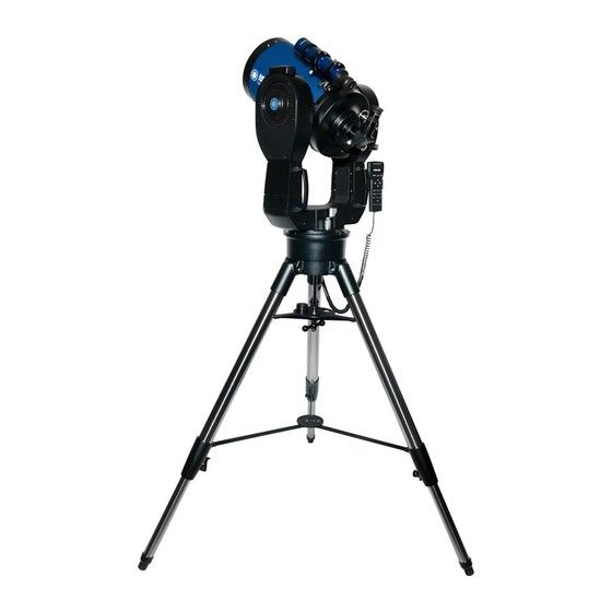
Meade LX200 Classic Service Manual
Procedures for removal and installation of printed circuit board and motor assemblies
Hide thumbs
Also See for LX200 Classic:
- Instruction manual (93 pages) ,
- Service (6 pages) ,
- Instruction manual (65 pages)
Advertisement
Quick Links
Procedures for Removal and Installation of Printed Circuit Board
STATIC ELECTRICITY HAZARD AND PREVENTION
Static electricity can easily damage the electronics of your telescope. Great care should
be observed in the handling of the electronics to prevent damage. Note that it is very
easy to generate several thousand volts of static electricity on plastic surfaces just by
handling them. This includes plastic bags, bubble wrap, styrafoam packing materials, as
well as indoor carpet. Take the following precautions:
• Work on metal or wooden surfaces.
• DO NOT work in an area with a rug on the floor.
• Be sure to discharge yourself by touching the metal of the telescope BEFORE
handling the electronics.
• DO NOT put the printed circuit board in a plastic bag unless you have the type
designed for holding electronics (conductive plastic bags).
• DO wrap the printed circuit board in aluminum foil before packing it in a box if
you don't have a conductive plastic bag.
Telescope Service
Meade LX200 "Classic" Telescopes
And Motor Assemblies
Advertisement

Related Manuals for Meade LX200 Classic


Summary of Contents for Meade LX200 Classic
- Page 1 Telescope Service Meade LX200 “Classic” Telescopes Procedures for Removal and Installation of Printed Circuit Board And Motor Assemblies STATIC ELECTRICITY HAZARD AND PREVENTION Static electricity can easily damage the electronics of your telescope. Great care should be observed in the handling of the electronics to prevent damage. Note that it is very easy to generate several thousand volts of static electricity on plastic surfaces just by handling them.
- Page 2 Tools Needed o Phillips head screwdriver (medium size) o 1/16 hex wrench (Allen head) o 5/64 hex wrench (Allen head) o Putty knife or other thin bladed tool o Solvent (Alcohol) Printed Circuit Board (PCB) Removal WARNING Static Electricity can damage the electronics of your telescope. Review the section on Static Electricity prevention and electronics handling before proceeding.
- Page 3 Pic 1...
- Page 4 Pic 2...
- Page 5 Printed Circuit Board (PCB) Installation WARNING Static Electricity can damage the electronics of your telescope. Review the section on Static Electricity prevention and electronics handling before proceeding. 1. Check the back of the circuit board for nylon standoff washers which are glued over the mounting holes to insulate the PCB from the base.
- Page 6 Pic 3...
- Page 7 R.A. Motor Removal 1. Disconnect the R.A. Motor cable (7 Pin connector) from the Printed Circuit Board. 2. Remove the 2 hex (Allen) screws holding the RA Motor assembly to the drive base. Be very careful you don’t drop the hex screws down into the base as it’s very difficult to retrieve them, and you could jam the worm gear.
- Page 8 R.A. Motor Assembly Installation 1. Align the RA motor assembly with the two threaded mounting holes. Note that some motor assemblies have a step in the base of the mount which requires a special mounting plate. We recommend you smear some grease on the base and mounting plate to hold them together while installing the motor assembly.
- Page 9 DEC Motor Removal 1. Remove the declination lock knob (unthread) 2. Remove the plastic cover that is attached by three mounting screws 3. At this point it is a good idea to see how the motor assembly lines up with the fork arm mounting holes.
- Page 10 Pic 5 Declination Motor Installation 1. Pass the power cable of the motor assembly through the opening I the fork arm and plug it into the RJ-45 jack inside the fork arm. 2. Center the motor assembly over the two threaded mounting holes in the fork arm housing.
- Page 11 6. Semi-tighten the left mounting screw, push up on the motor block to level the assembly and tighten the right mounting screw. Tighten the left mounting screw. Check the worm gear and worm wheel meshing to ensure a good fit. 7.
Need help?
Do you have a question about the LX200 Classic and is the answer not in the manual?
Questions and answers