Table of Contents
Advertisement
Quick Links
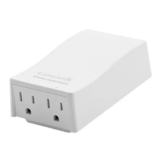
Wireless Outlet
Switch Installation
Supported Models and Requirements
LOZ-5S1-W
Wireless Outlet Switch
Graphical Symbols in this Guide
The following symbols and their descriptions draw your attention to important safe
practices and additional information that can help you avoid injury, death, or loss of
material or time.
WARNING! This indicates a potentially hazardous situation that, if not
avoided, may result in death or serious injury.
CAUTION! This indicates a potentially hazardous situation that, if not avoided,
may result in minor or moderate injury.
IMPORTANT!
This indicates information that will help you avoid damage to
your equipment, loss of materials, or loss of time.
IMPORTANT STATEMENTS!
Specifications and Supported Fixtures
This Wireless Outlet Switch plugs into a standard, earth-grounded (3-prong)
electrical outlet and communicates with the Control4 system using a wireless
ZigBee connection through its built-in antenna.
Use the Wireless Outlet Switch to control electrical devices such as pumps,
Christmas lights, fans, and fluorescent lights, individually or within a lighting
scene. The Wireless Outlet Switch can sense the power state of the devices
attached to it (On, Off, or Stand-by).
WARNING! The Wireless Outlet Switch is rated for a combined load of 1150
Watts; do not plug in devices that require more than 1150 Watts, either alone or
in combination.
The Control4 Wireless Outlet Switch offers these features:
•
Power sensors allow the Control4 system to detect the power state
of the devices you have plugged into each outlet.
•
Two tri-color LEDs to indicate outlet activity and system feedback.
•
A security screw tab that attaches to the outlet's center screw.
•
An external button for manual operation and to automatically identify
the device to the Control4 system.
Specifications
Power Requirements:
120 VAC, 50/60 Hz, 1.7 W
Load Ratings:
120 VAC, 1150 VA, Inductive, Total
(Total of Both Outlets)
120 VAC, 1/3 HP (7.2 FLA), Total
120 VAC, 7.2 A, Ballast, Total
Operating
All load ratings are based on an ambient
Temperature:
temperature of 25 degrees Celsius.
Guide
DO NOT IGNORE A WARNING!
DO NOT IGNORE A CAUTION!
PAY ATTENTION TO THESE
Important Warnings and Information
WARNING! Improper use or installation can cause SERIOUS
INJURY, DEATH, or LOSS/DAMAGE OF PROPERTY.
WARNING! Install in accordance with all national, state, and local
electrical codes.
This product generates heat. The room must have
WARNING!
adequate ventilation or the ability to dissipate heat effectively.
WARNING! This product must be grounded in accordance with the
National Electrical Code (NEC) requirements.
WARNING! Use only in dry locations.
For residential use only.
CAUTION!
Using this product in a manner other than outlined in this
IMPORTANT!
document voids your warranty. Further, Control4 is not liable for any
damage incurred because of the misuse of this product. See "Limited
1 Year Warranty" on page 2.
Install and Configure a Wireless Outlet Switch
To enable full use of the Control4 system's features, configure your Wireless
Outlet Switch to read the power state of the devices that you plug into it. For
example, if your switch can read the power state of the DVD player, your
DVD player can then participate in concert with the lights and the other
devices in your home theater in a lighting scene.
1
Choose a location where the ZigBee wireless communication will be
most efficient: (1) Place the Outlet Switch near enough to the next
ZigBee device to facilitate communication (2); Keep the Outlet Switch
from being continually too close to devices that can cause interference,
such as microwave ovens or cordless telephones with a 2.4 GHz
frequency.
2
Remove the screw that holds the faceplate onto
the AC outlet to which you will plug the Wireless
Outlet Switch.
3
Plug the Wireless Outlet Switch into the
receptacle of the outlet, keeping the faceplate
between the Wireless Outlet Switch and the
wall.
4
Through the Wireless Outlet Switch's security screw tab, insert the
screw that you removed in Step 2 and then screw it back in place.
5
Within Composer software, add the outlet to the project and make
necessary connections. See "Configure an Outlet Switch or Dimmer" in
Composer online help.
To identify the Wireless Outlet Switch as part of the Composer software
configuration, press the button on the top panel of the Wireless Outlet
Switch.
6
Plug in the device you would like to control, such as a DVD player, into
one of the Wireless Outlet Switch's receptacles (on the bottom panel).
7
Push and hold the button on the top panel of the Wireless Outlet Switch
until the two LED lights flash orange, On and Off, from one to the next.
8
When the LED lights up on the side that corresponds to the outlet in
which your device is plugged, release the button. For example, if the
device you have plugged in is on the right side of the Wireless Outlet
Switch, release the button when the LED lights on the right side.
The LED on that side of the switch alone flashes orange, indicating that
it is in the first phase of learning the state (Off) of the device. When it
has completed this learning phase, the LED then shines solid orange.
9
When the LED shines solid orange, turn On the device that you have
plugged into the Wireless Outlet Switch. The LED light again flashes
orange while the Wireless Outlet Switch completes the first phase of
Advertisement
Table of Contents

Related Manuals for Control 4 LOZ-5S1-W


Summary of Contents for Control 4 LOZ-5S1-W
- Page 1 See “Limited 1 Year Warranty” on page 2. Supported Models and Requirements LOZ-5S1-W Wireless Outlet Switch Install and Configure a Wireless Outlet Switch To enable full use of the Control4 system’s features, configure your Wireless Graphical Symbols in this Guide Outlet Switch to read the power state of the devices that you plug into it.
- Page 2 learning the electrical currents associated with this state (On) of the device. FCC ID: R33L0Z5S11 When the Wireless Outlet Switch has competed the first phase of This device complies with Part 15 of the FCC Rules. Operation is subject to learning the On state, it shines solid orange again.
Need help?
Do you have a question about the LOZ-5S1-W and is the answer not in the manual?
Questions and answers