Subscribe to Our Youtube Channel
Summary of Contents for PerkinElmer PS-1120
- Page 1 (217) 352-9330 | Click HERE Find the Perkin Elmer PS-1120-1 at our website:...
- Page 2 A B C R D PS-1120 POWER SUPPLY OPERATION MANUAL PerkinElmer Optoelectronics 35 Congress St., Salem, MA 01970 USA Phone: (978)745-3200 FAX: (978)745-0894 Toll Free: (800)950-3441 in USA only Website http://www.perkinelmer.com/opto E-mail opto@perkinelmer.com FF0091 UM0024 Rev L Artisan Technology Group - Quality Instrumentation ... Guaranteed | (888) 88-SOURCE | www.artisantg.com...
- Page 3 Heatsinking of metal-can flashlamps and Lite-Pacs is required when these devices are operated above 25 watts. WARNUNG! Das Netzteil PS-1120 erzeugt bis zu 20 Watt Ausgang. Bei Leistungen höher als 25 Watt müssen Dosenlampe sowie Triggermodul, mittels eines Kühlblechs, abgekühlt werden. ATTENTION! L'alimentation PS-1120 fournit jusqu' à...
-
Page 4: Table Of Contents
FIGURES FIGURE 1. OPTIONAL PERKINELMER LITE-PACS AND ACCESSORIES ..........2 FIGURE 2. OUTLINE AND MOUNTING DIMENSIONS ................4 FIGURE 3. PS-1120 TYPICAL CHARGE RATE CURVES................ 5 FIGURE 4. OUTPUT VOLTAGE VS. TIME....................5 FIGURE 5. INPUT TRIGGER CIRCUIT....................... 6 FIGURE 7. -
Page 5: Introduction
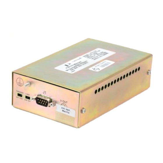
A B C R D PS-1120 POWER SUPPLY OPERATION MANUAL INTRODUCTION DESCRIPTION The PS-1120 POWER SUPPLY is one of a series of Power Supplies designed for high energy capacitor discharge service with any guided arc bulb-type flashlamp and Lite-Pac® including those shown below. LITE-PACS... -
Page 6: Specifications
A B C R D PS-1120 POWER SUPPLY OPERATION MANUAL SPECIFICATIONS Table 1. Electrical Input Voltage 15-28V DC Current Less than 1.2A DC @ 24V DC, 20W output Optically isolated; 20-50mA peak input; 10-20µs pulse Trigger width; leading edge trigger. Int. series resistor = 150Ω. -
Page 7: Installation
A B C R D PS-1120 POWER SUPPLY OPERATION MANUAL INSTALLATION MOUNTING Two 6-32 UNC threaded holes in the base of the enclosure are provided for mounting the unit (see Figure 2). Mounting hardware is user-supplied. PS-1120 POWER SUPPLY A SHIELDING ENTRANCE PLATE FOR J2 IS PROVIDED. -
Page 8: Operating Conditions
At 24V input, 600V output, the unit delivers a minimum of 20 joules per second to the discharge capacitor. Figure 3.1 shows typical charge rate values vs output voltage for four different DC inputs. Figure 3. PS-1120 Typical Charge Rate Curves. The energy per discharge is given by the expression: J = Discharge energy... -
Page 9: Operation
Figure 5. Input Trigger Circuit The PS-1120 can be tested for proper Operation by moving the TRIGGER switch to the INT position. The unit should now flash at a low rate. INTERNAL ADJUSTMENT OF HV OUTPUT REFERENCE VOLTAGE... -
Page 10: Interconnections
A B C R D PS-1120 POWER SUPPLY OPERATION MANUAL INTERCONNECTIONS Make input connections according to Figure 7 and 9 or 10 (whichever is appropriate). Make output connections according to Figure 8 and 9 or 10. When using a standard wiring Figure 7. -
Page 11: Maintenance
Repairs must be made only by factory-trained personnel. REPACKING AND STORAGE If the PS-1120 is to be stored for a prolonged period, shipped to another location, or returned to the factory for repair, it should be repacked in the original packaging material.

Need help?
Do you have a question about the PS-1120 and is the answer not in the manual?
Questions and answers