Table of Contents
Advertisement
Quick Links
Advertisement
Table of Contents

Related Manuals for METER ATMOS 14


Summary of Contents for METER ATMOS 14
- Page 1 ATMOS 14...
-
Page 2: Table Of Contents
....................1 2. Operation ....................2 2.1 Installation ....................2 2.2 Connecting ....................4 2.2.1 Connect to METER Logger ..............4 2.2.2 Connect to Non-METER Logger ............5 2.3 Communication ..................6 3. System ......................7 3.1 Specifications .................... 7 3.2 Components .................... -
Page 4: Introduction
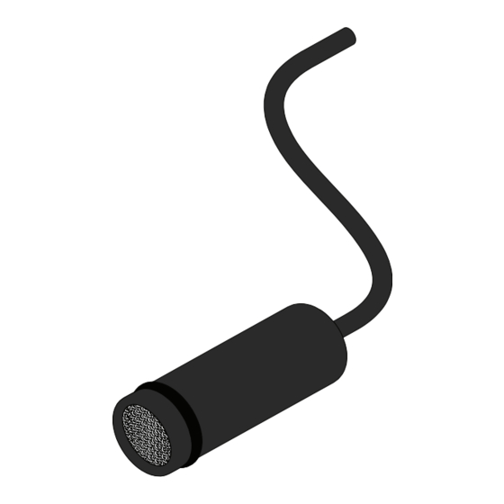
ATMOS 14 1. INTRODUCTION Thank you for choosing the ATMOS 14 temperature and relative humidity (RH) sensor from METER Group. The ATMOS 14 is designed to measure the following: • Air temperature • RH • Barometric pressure • Vapor pressure... -
Page 5: Operation
METER sensors are built to the highest standards, but misuse, improper protection, or improper installation may damage the sensor and possibly void the manufacturer’s warranty. Before integrating ATMOS 14 into a system, follow the recommended installation instructions and have the proper protections in place to safeguard sensors from damage. - Page 6 Install cables in conduit or plastic cladding when near the ground to avoid rodent damage. Gather and secure cables between the ATMOS 14 and the data logger to the mounting mast in one or more places. Connect to Data Logger Plug the sensor into a data logger.
-
Page 7: Connecting
OPERATION 2.2 CONNECTING The ATMOS 14 seamlessly with METER data loggers. The sensor can also be used with other data loggers, such as those from Campbell Scientific, Inc. For extensive directions on how to integrate the sensor into third-party loggers, refer to the ATMOS 14 Integrator Guide. -
Page 8: Connect To Non-Meter Logger
Data Logger Figure 3 Wiring diagram NOTE: The acceptable range of excitation voltages is from 3.6 to 15.0 VDC. To read the ATMOS 14 with Campbell Scientific data loggers, power the sensors off a switched 12-V port. If the ATMOS 14 cable has a standard stereo plug connector and needs to be connected to... -
Page 9: Communication
ATMOS 14 Integrator Guide. The SDI-12 protocol requires that all sensors have a unique address. ATMOS 14 sensor factory default is an SDI-12 address of 0. To add more than one SDI-12 sensor to a bus, the sensor address must be changed as described below: Using a PROCHECK connected to the sensor, press the MENU button to bring up the Configuration tab. -
Page 10: System
ATMOS 14 3. SYSTEM This section describes the ATMOS 14 sensor. 3.1 SPECIFICATIONS MEASUREMENT SPECIFICATIONS Relative Humidity (RH) Range 0–100% RH (0.00–1.00) Resolution 0.1% RH Accuracy Sensor measurement accuracy is variable across a range of RH. Refer to the chart in Figure 4. - Page 11 SYSTEM Accuracy Sensor measurement accuracy is variable across a range of temperatures. Refer to the chart in Figure 5. Figure 5 Temperature sensor accuracy Equilibration <400 s (response time in 1 m/s air stream Time (τ, 63%) Long-Term Drift <0.04 °C/year, typical Vapor Pressure Range 0–47 kPa...
- Page 12 ATMOS 14 Barometric Pressure Range 50–110 kPa Resolution 0.01 kPa ±0.4 kPa Accuracy COMMUNICATION SPECIFICATIONS Output DDI serial or SDI-12 communication Data Logger Compatibility Any data acquisition system capable of 3.6- to 15.0-VDC power and serial or SDI-12 communication. PHYSICAL SPECIFICATIONS...
- Page 13 SYSTEM ELECTRICAL AND TIMING CHARACTERISTICS Supply Voltage (VCC to GND) Minimum 3.6 VDC Typical Maximum 15.0 VDC Digital Input Voltage (logic high) Minimum 2.8 V Typical 3.0 V Maximum 5.5 V Digital Input Voltage (logic low) Minimum –0.3 V Typical 0.0 V Maximum 0.8 V...
- Page 14 ATMOS 14 Power Up Time (DDI serial) Minimum Typical Maximum 100 ms Power Up Time (SDI-12) Minimum 100 ms Typical 1,100 ms Maximum 1,100 ms Measurement Duration Minimum Typical 550 ms Maximum 600 ms COMPLIANCE Manufactured under ISO 9001:2015 2004/108/EC and 2011/65/EU...
-
Page 15: Components
filter and sensors Figure 7 ATMOS 14 components The ATMOS 14 uses a primary sensor chip to measure RH and air temperature (Section 3.2.2) and a secondary chip to measure barometric pressure (Section 3.2.3). A microprocessor within the ATMOS 14 calculates vapor pressure from the RH and temperature measurements. -
Page 16: Barometric Pressure Sensor
The barometric pressure sensor measures the atmospheric pressure of the environment in which the ATMOS 14 is deployed. With a range from 49 to 109 kPa, it is suitable for measurement across a wide range of elevations, but the magnitude of sensor output will depend chiefly on the installation altitude with subtle changes caused by weather. -
Page 17: Relative Humidity
0 °C introduce errors due to the use of liquid water as the reference. However, because the Buck (1981) formulation for liquid water is used to calculate vapor pressure over the full temperature range, ATMOS 14 vapor pressure output values are correct over the full temperature range. -
Page 18: Service
Seal the ATMOS 14 sensor into the container, making sure that the ATMOS 14 is held or suspended above the salt solution . NOTE: Ensure the ATMOS 14 sensor is at the same temperature as the salt solution or large errors in the measured RH occur. -
Page 19: Troubleshooting
NaCl 6.00 If the ATMOS 14 sensor has lost accuracy due to exposure to solvents or other chemicals, the following conditioning procedure may bring the sensor back to the original calibration state: Bake the sensor in dry heat at 100 to 105 °C for 10 h. -
Page 20: Customer Support
(make sure it is fully shaded). This includes direct, diffuse, incident, and reflected solar radiation. Ensure that the ATMOS 14 radiation shield is mounted in a location with adequate ventilation/wind speed to bring the sensor to air temperature. Sensor not reading... -
Page 21: Terms And Conditions
NOTE: For products purchased through a distributor, please contact the distributor directly for assistance. 4.5 TERMS AND CONDITIONS By using METER instruments and documentation, you agree to abide by the METER Group, Inc. USA Terms and Conditions. Please refer to metergroup.com/terms-conditions... -
Page 22: References
ATMOS 14 REFERENCES Buck, Arden L. 1981. New Equations for Computing Vapor Pressure and Enhancement Factor. Journal of Applied Meteorology. 20 (12):1527–1432. Murray, F.W. 1967. On the Computation of Saturation Vapor Pressure. Journal of Applied Meteorology. 6:203–204. World Meteorological Organization (WMO). 2008. Guide to Meteorological Instruments and... -
Page 23: Index
INDEX INDEX phone number 17 applications 1 references 19 barometric pressure 9, 13 relative humidity 7, 12, 14 calibration 15 salt solution 15–16 cleaning. See maintenance sensor poisoning 15 compliance 11 specifications components 12–13 communication 9 barometric pressure sensor 13 filter 12 electrical and timing 10–11 physical 9 radiation shield 2, 12, 15... - Page 24 18014-03 1.17.2020 METER Group, Inc. USA 2365 NE Hopkins Court Pullman, WA 99163 T: +1.509.332.2756 F: +1.509.332.5158 E: info@metergroup.com W: metergroup.com METER Group AG Mettlacher Straße 8, 81379 München T: +49 89 1266520 F: +49 89 12665220 E: info.europe@metergroup.com W: metergroup.de...
Need help?
Do you have a question about the ATMOS 14 and is the answer not in the manual?
Questions and answers