Table of Contents
Advertisement
Advertisement
Table of Contents

Related Manuals for METER TEROS 11


Summary of Contents for METER TEROS 11
- Page 1 TEROS 11/12...
-
Page 2: Table Of Contents
1. Introduction ....................1 2. Operation ....................2 2.1 Installation ....................2 2.2 Connecting ....................6 2.2.1 Connect to METER Logger ..............6 2.2.2 Connect to Non-METER Logger............7 2.3 Communication ..................8 3. System ....................... 10 3.1 Specifications ..................10 3.2 Components .................... - Page 3 4.2 Cleaning ....................19 4.3 Troubleshooting ..................19 4.4 Customer Support..................20 4.5 Terms and Conditions ................21 References ....................22 Index ......................... 23...
-
Page 5: Introduction
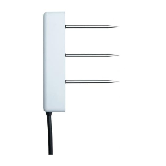
VWC using capacitance/frequency-domain technology. The sensor uses a 70-MHz frequency, which minimizes textural and salinity effects, making the TEROS 11/12 accurate in most mineral soils. The TEROS 11/12 uses a thermistor in the center needle to measure temperature and EC (TEROS 12 only) using a stainless-steel electrode array. -
Page 6: Operation
Please read all instructions before operating the TEROS 11/12 to ensure it performs to its full potential. SAFETY PRECAUTIONS METER sensors are built to the highest standards. Misuse, improper protection, or improper installation may damage the sensor and possibly void the manufacturer’s warranty. Before integrating the TEROS 11/12 into a system, follow the recommended installation instructions and have the proper protections in place to safeguard sensors from damage. - Page 7 Insert Sensor Determine sensor orientation. The TEROS 11/12 sensor may be positioned in any direction. However, with the body in a vertical position (as shown below), there is less restriction to water flow. A vertical position will also integrate more soil depth into the soil moisture measurement.
- Page 8 Install cables in conduit or plastic cladding when near the ground to avoid rodent damage. Gather and secure cables between the TEROS 11/12 and the data logger to the mounting mast in one or more places. Connecting...
- Page 9 TEROS 11/12 Table 2 Installation methods Borehole Advantage Disadvantage This method uses the Borehole Installation Tool (Table 1) that Minimizes soil Requires a allows a profile of soil moisture disturbance at specialized sensors to be installed at measurement installation different depths within a single site.
-
Page 10: Connecting
TEROS 11/12 sensors come with a 3.5-mm stereo plug connector (Figure 1) to facilitate easy connection with METER data loggers. TEROS 11/12 sensors may be ordered with stripped and tinned wires to facilitate connecting to some third-party loggers (Section 2.2.2). Ground Data output... -
Page 11: Connect To Non-Meter Logger
Utility or ZENTRA Cloud. Refer to the logger user manual for more information about these programs. 2.2.2 CONNECT TO NON-METER LOGGER The TEROS 11/12 can be purchased for use with non-METER (third-party) data loggers. Refer to the third-party logger manual for details on logger communications, power, and ground ports. The TEROS 11/12 Integrator Guide... -
Page 12: Communication
TEROS 11/12 Integrator Guide. The SDI-12 protocol requires that all sensors have a unique address. TEROS 11/12 sensor factory default is an SDI-12 address of 0. To add more than one SDI-12 sensor to a bus, the sensor address must be changed as described below: Using a ProCheck connected to the sensor, press the Menu button to bring up the CONFIG menu. - Page 13 Detailed information can also be found in the application note Setting SDI-12 addresses on METER digital sensors using Campbell Scientific data loggers and LoggerNet. When using the sensor as part of an SDI-12 bus, excite the sensors continuously to avoid...
-
Page 14: System
1–40 (soil range) , ±1 (unitless) ε permittivity ( 40–80, 15% of measurement Dielectric Measurement Frequency 70 MHz Temperature TEROS 11 Range −40 to +60 °C Resolution 0.1 °C Accuracy ±1 °C from −40 to 0 °C ±0.5 °C from 0 to +60 °C NOTE: Temperature measurement, for applicable sensors, may not be accurate if sensor is not fully immersed in the medium of interest, due to longer equilibration time. - Page 15 ±8% from 10–20 dS/m COMMUNICATION SPECIFICATIONS Output DDI serial or SDI-12 communications protocol Data Logger Compatibility METER ZL6, EM60, and Em50 data loggers or any data acquisition system capable of 4.0- to 15-VDC power and serial or SDI-12 communication PHYSICAL SPECIFICATIONS Dimensions Length 9.4 cm (3.70 in)
- Page 16 SYSTEM ELECTRICAL AND TIMING CHARACTERISTICS Supply Voltage (VCC to GND) Minimum 4.0 VDC Typical Maximum 15.0 VDC Digital Input Voltage (logic high) Minimum 2.8 V Typical 3.6 V Maximum 3.9 V Digital Input Voltage (logic low) Minimum –0.3 V Typical 0.0 V Maximum 0.8 V...
-
Page 17: Components
TEROS 11/12 Operating Temperature Range Minimum –40 °C Typical Maximum +60 °C NOTE: Sensors may be used at higher temperatures under certain conditions; contact Customer Support for assistance. Power-Up Time (DDI serial) Minimum 80 ms Typical Maximum 100 ms Power-Up Time (SDI-12) - Page 18 The TEROS 11/12 VWC measurement sensitivity is contained within a 1,010-mL volume roughly depicted in Figure 5. Please see the application note Measurement volume of METER volumetric water content sensors for testing protocol and more thorough analysis. 9.3 cm 1 cm...
-
Page 19: Theory
4.1). 3.3.2 TEMPERATURE The TEROS 11 uses a small thermistor mounted on the PCB near the lower needle. The TEROS 11 temperature measurement is optimized to be accurate when the TEROS 11 is fully buried in soil or substrate. The TEROS 12 uses a thermistor in the center needle to take temperature readings and responds faster to temperature changes and is better suited for needle-only insertion into greenhouse and nursery substrates. -
Page 20: Pore Water Versus Saturation Extract Ec (Teros 12 Only)
= 0 improves the accuracy of the calculation of in most cases. METER testing indicates that the method for calculating (Equation 1) results in good accuracy (±20%) in moist soils and other growth media. In dry soils, where VWC is less than 0.10 m... - Page 21 TEROS 11/12 Saturation extract EC is the EC of pore water removed from a saturated paste. Saturation extract EC can be measured directly if distilled water is used to wet the soil until the soil saturates. The soil is then placed on filter paper in a vacuum funnel and suction is applied.
-
Page 22: Service
(i.e., potting soil, perlite, or peat moss), and dielectric permittivity. However, for added accuracy, customers are encouraged to perform soil-specific calibrations. For more information on how to calibrate sensors or to learn about METER calibration service (calibrations performed for a standard fee), see soil sensor calibration or contact Customer Support. -
Page 23: Apparent Dielectric Permittivity
TEROS 11/12 4.1.3 APPARENT DIELECTRIC PERMITTIVITY Apparent dielectric permittivity ( ) can be used to determine VWC using external published equations such as the Topp equation (Topp et al. 1980). Dielectric permittivity is also used for calculating pore water EC. Dielectric permittivity is given by Equation −9... -
Page 24: Customer Support
SERVICE Table 3 Troubleshooting the TEROS 11/12 (continued) Problem Possible Solution Check to make sure that the media was not packed excessively or insufficiently during sensor installation. Higher density can cause sensor reading to be elevated. Ensure the calibration equation being used is appropriate for the media type. There are significant differences between calibrations, so be sure to use the Sensor reading one most suitable to the substrate, or consider developing a substrate-specific... -
Page 25: Terms And Conditions
NOTE: For products purchased through a distributor, please contact the distributor directly for assistance. 4.5 TERMS AND CONDITIONS By using METER instruments and documentation, you agree to abide by the METER Group, Inc. USA Terms and Conditions. Please refer to www.metergroup.com/company/meter-group-... -
Page 26: References
REFERENCES REFERENCES Hilhorst, M. A. 2000. "A pore water conductivity sensor." Soil Science Society of America Journal 64 (6):1922–1925. Topp, G. Clarke, J. L. Davis, and Aa P. Annan. 1980. "Electromagnetic determination of soil water content: Measurements in coaxial transmission lines." Water resources research 16 (3): 574–582. -
Page 27: Index
11 phone number 20 ferrite core 14 needles 11, 13 thermistor 13 references 22 configuration See data loggers, connect to METER logger customer support 20 safety 2 soil moisture 13 specifications 10–13 data loggers 6–7, 11 data logger compatibility 11... - Page 28 INDEX temperature theory 15 terms and conditions 21–22 theory 15–18 electrical conductivity 15–17 See also electrical conductivity temperature 15 volumetric water content 15 See theory, volumetric water content troubleshooting 19–20 volumetric water content specifications 10 theory 15...
- Page 29 18226-01 2.15.2019 METER Group, Inc. USA 2365 NE Hopkins Court Pullman, WA 99163 T: +1.509.332.5600 F: +1.509.332.5158 E: info@metergroup.com W: metergroup.com METER Group AG Mettlacher Straße 8, 81379 München T: +49 89 1266520 F: +49 89 12665236 E: info@metergroup.de W: metergroup.de...
Need help?
Do you have a question about the TEROS 11 and is the answer not in the manual?
Questions and answers