Table of Contents
Advertisement
Advertisement
Table of Contents

Subscribe to Our Youtube Channel
Related Manuals for METER TEROS 21


Summary of Contents for METER TEROS 21
- Page 1 TEROS 21...
-
Page 3: Table Of Contents
13755-03 11.10.2017 TABLE OF CONTENTS 1. Introduction ....................1 2. Operation ....................2 2.1 Installation ....................2 2.2 Connecting ....................3 3. System ......................6 3.1 Specifications .................... 6 3.2 Components ....................9 3.3 Theory ......................9 3.3.1 Water Potential Measurement ............9 3.3.2 Measurement Range .............. -
Page 5: Introduction
TEROS 21 1. INTRODUCTION Thank you for purchasing the TEROS 21 Soil Water Potential Sensor from METER Group. TEROS 21 was designed to be a maintenance-free matric potential sensor designed for long- term, continuous field measurements. The TEROS 21 measures the dielectric permittivity of a solid matrix to determine the water content of the solid matrix. -
Page 6: Operation
OPERATION 2. OPERATION Please read all instructions before operating the TEROS 21 to ensure it performs to its full potential. SAFETY PRECAUTIONS METER sensors are built to the highest standards, but misuse, improper protection, or improper installation may damage the sensor and possibly void the manufacturer’s warranty. -
Page 7: Connecting
Return soil to the hole, packing the soil back to its native bulk density. 2.2 CONNECTING The TEROS 21 sensors work best with METER data loggers or ProCheck handheld readers. 1. Check data logger software and firmware versions to ensure they support TEROS 21 sensors (http://www.metergroup.com/teros21-support/). - Page 8 Please refer to the complete TEROS 21 Integrator Guide for more detailed explanations and instructions. There are two options to connect a sensor with the standard stereo plug to a non-METER data logger. Option 1 1. Clip the plug off the sensor cable.
- Page 9 SDI-12 communications. SDI-12 communication can convey multiple parameters from a single function call. In the data stream, TEROS 21 reports (1) the sensor address, (2) the water potential (in kilopascals), and (3) the temperature (in Celsius).
-
Page 10: System
SYSTEM 3. SYSTEM This section reviews the components and functionality of the TEROS 21 sensor. 3.1 SPECIFICATIONS Measurement Specifications Water Potential Range: −9 to −100,000 kPa (1.96 to 6.01 pF) Resolution: 0.1 kPa Accuracy: ±(10% of reading + 2 kPa) from −9 to −100 kPa... - Page 11 TEROS 21 Output RS232 (TTL) with 3.9-VDC levels or SDI-12 communication protocol Connector Types 3.5-mm stereo plug connector or stripped and tinned wires Cable Length 5 m (standard) 75 m (maximum custom cable length) Data Logger Compatibility Any data acquisition system capable of 3.9- to 15.0-VDC power and serial or...
- Page 12 SYSTEM Current Drain (during measurement) Minimum 3.0 mA Typical 3.6 mA Maximum 10.0 mA Current Drain (while asleep) Minimum Typical 0.03 mA Maximum Operating Temperature Range Minimum –40 °C Typical Maximum 50 °C Power Up Time (DDI serial) Minimum Typical Maximum 100 ms Power Up Time (SDI-12)
-
Page 13: Components
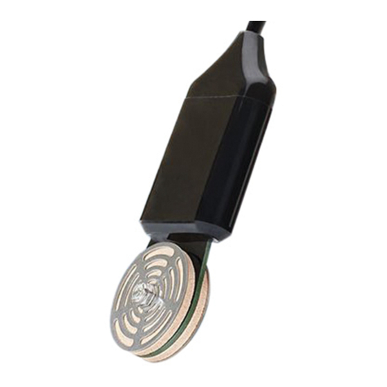
(static matrix) Figure 3 TEROS 21 sensor 3.3 THEORY TEROS 21 sensors measure water potential, so they are not as sensitive to soil disturbance as water content sensors. TEROS 21 need good hydraulic contact with the surrounding soil for accurate measurements. -
Page 14: Measurement Range
Water content and water potential are related by a relationship unique to a given material, called the moisture characteristic curve. The ceramic used with the TEROS 21 has a wide pore size distribution and is consistent between discs, giving each disc the same moisture characteristic curve. - Page 15 10,000 100,000 WATER POTENTIAL (-kPa) Figure 4 Moisture characteristic curve of TEROS 21 ceramic derived from mercury porosimeter data DRY-END LIMITATIONS As the sensor dries past the plant-available range, the total pore volume that drains at a given water potential decreases. At these low water potentials, the measured water potential can become somewhat noisy because small changes in measured water content of the ceramic translate into large changes in water potential.
-
Page 16: Measurement Accuracy
SYSTEM 3.3.3 MEASUREMENT ACCURACY TEROS 21 is calibrated at a saturated state (0 kPa), at an air-dry state (−100,000 kPa), and at three calibration points between 0 and −100 kPa, resulting in accuracy of ±(10% of reading + 2 kPa) over the range of −9 to −100 kPa. -
Page 17: Temperature Measurement
−3,500.0 −4,000.0 −4,500.0 Figure 6 Time series TEROS 21 water potential data collected at 20 cm under a dry oak forest in Switzerland (Walthert 2013). Note the range extends well beyond permanent wilting point. 3.3.4 TEMPERATURE MEASUREMENT TEROS 21 uses a surface-mounted thermistor to take temperature readings. The thermistor is located underneath the sensor epoxy. -
Page 18: Measuring In High Salinity
A saturation extract electrical conductivity (EC) greater than 10 dS/m will confound the capacitance measurement taken by the sensor resulting in erroneous matric potential readings. It is recommend that the TEROS 21 only be used in environments where the saturation extract EC does not exceed 10 dS/m. -
Page 19: Service
TEROS 21 calibration is not affected by soil type because the sensors only measure the water potential of the ceramic discs in equilibrium with the soil. TEROS 21 works in any soil type or other porous media as long as it is installed correctly with adequate hydraulic contact (to ensure timely water potential equilibrium between the sensor and the medium of interest). -
Page 20: Troubleshooting
If contacting METER by email or fax, please include the following information: Name Email address Address Instrument serial number Phone Description of the problem NOTE: For TEROS 21 Soil Water Potential sensors purchased through a distributor, please contact the distributor directly for assistance. -
Page 21: Terms And Conditions
PRICES AND PAYMENT. Invoice prices will be based upon METER prices as quoted or at METER list price in effect at the time an order is received by the Seller. Prices do not include any state or federal taxes, duties, fees, or charges now or hereafter enacted applicable to the goods or to this transaction, all of which are the responsibility of the Buyer. - Page 22 SERVICE WARRANTIES. The Seller warrants all equipment manufactured by it to be free from defects in parts and labor for a period of one year from the date of shipment from factory. The liability of the Seller applies solely to repairing, replacing, or issuing credit (at the Seller’s sole discretion) for any equipment manufactured by the Seller and returned by the Buyer during the warranty period.
-
Page 23: References
TEROS 21 REFERENCES Bittelli M and Flury M. 2009. Errors in water retention curves determined with pressure plates. Soil Sci Soc Am J. 73:1453–1460. Campbell GS. 1988. Soil water potential measurement: an overview. Irrigation Sci. 9:265–273. Frydman S and Baker R. 2009. Theoretical soil–water characteristic curves based on adsorption, cavitation, and a double porosity model. -
Page 24: Index
SERVICE INDEX cable colors 4 specifications 6–7 calibration 12, 15 cable length 7 ceramic pore size 13–14 dimensions 6 cleaning. See maintenance components ceramic discs 9, 10, 10–11, 15, 16 temperature 6, 9, 13 circuit board 9 terms and conditions 17–18 screens 9, 15 theory sensor body 3, 9, 13... - Page 25 14567-01 11.10.2017 METER Group 2365 NE Hopkins Court Pullman, WA 99163 T: +1.509-332-2756 F: +1.509.332.5158 E: info@metergroup.com W: www.metergroup.com © 2017 All Rights Reserved.
Need help?
Do you have a question about the TEROS 21 and is the answer not in the manual?
Questions and answers