Table of Contents
Advertisement
Quick Links
TEROS 11/12 INTEGRATOR GUIDE
SENSOR DESCRIPTION
The TEROS 11 Soil Moisture and Temperature sensor and the TEROS 12 Soil Moisture, Temperature,
and Electrical Conductivity (EC) sensor are accurate tools for monitoring volumetric water content
(VWC), temperature in soil and soilless substrates, and electrical conductivity (TEROS 12 only). The
TEROS 11/12 determines VWC using capacitance/frequency-domain technology. The sensor uses a 70 MHz
frequency, which minimizes textural and salinity effects, making the TEROS 11/12 accurate in most mineral
soils. The TEROS 11/12 uses a thermistor in the center needle to measure temperature and electrical
conductivity (TEROS 12 only) using a stainless-steel electrode array.
For a more detailed description of how this sensor makes measurements, refer to the
APPLICATIONS
TEROS 11
• Volumetric water content VWC
• Soil/substrate water balance
• Irrigation management
• Soil/substrate temperature measurement
• Plant growth research
TEROS 12
• Volumetric water content VWC
• Soil/substrate water balance
• Irrigation management
• Soil/substrate temperature measurement
• Solute/fertilizer movement
• Soil EC measurement
ADVANTAGES
• Three-wire sensor interface: power, ground, and data
• Digital sensor communicates multiple measurements over serial interface
• Robust thermistor for accurate temperature measurements
• Low-input voltage requirements
• Low-power design supports battery-operated data loggers
• Robust epoxy encapsulation resists corrosive environments
• Supports SDI-12 or DDI serial communications protocols
• Modern design optimized for low-cost sensing
PURPOSE OF THIS GUIDE
METER provides the information in this integrator guide to help customers establish communication
between these sensors and their data acquisition equipment or field data loggers. Customers using data
loggers that support SDI-12 sensor communications should consult the data logger user manual. METER
sensors are fully integrated into the METER system of plug-and-play sensors, cellular-enabled data loggers,
and data analysis software.
COMPATIBLE FIRMWARE VERSIONS
This guide is compatible with firmware versions 1.07 or newer.
METER Group, Inc. USA
2365 NE Hopkins Court, Pullman, WA 99163
T
+1.509.332.2756
F
+1.509.332.5158
E
info@metergroup.com
W
metergroup.com
TEROS 11/12 User
Manual.
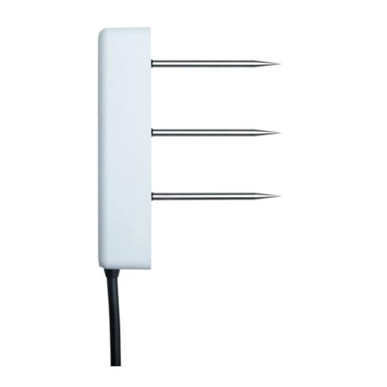
Figure 1 TEROS 11/12 sensor
18224-02
2.15.2019
Advertisement
Table of Contents

Related Manuals for METER Teros 11


Summary of Contents for METER Teros 11
- Page 1 TEROS 11/12 accurate in most mineral soils. The TEROS 11/12 uses a thermistor in the center needle to measure temperature and electrical conductivity (TEROS 12 only) using a stainless-steel electrode array.
-
Page 2: Measurement Specifications
±8% from 10–20 dS/m measurement COMMUNICATION SPECIFICATIONS Data Logger Compatibility Output METER ZL6, EM60, and Em50 data loggers DDI serial or or any data acquisition system capable of SDI-12 communication protocol 4.0- to 15-VDC power and serial or SDI-12 communication... - Page 3 2014/30/EU and 2011/65/EU EN61326-1:2013 and EN55022/CISPR 22 EQUIVALENT CIRCUIT AND CONNECTION TYPES Refer to Figure 2 Figure 3 to connect the TEROS 11/12 to a data logger. Figure 2 provides a low-impedance variant of the recommended SDI-12 specification. PIGTAIL CABLE Power (brown)
-
Page 4: Safety Precautions
DDI SERIAL INTRODUCTION The DDI serial protocol is the method used by the METER data loggers for collecting data from the sensor. This protocol uses the data line configured to transmit data from the sensor to the receiver only (simplex). Typically, the receive side is a microprocessor UART or a general-purpose I/O pin using a bitbang method to receive data. -
Page 5: Sdi-12 Timing
SDI-12 standard. Out of the factory, all METER sensors start with SDI-12 address 0 and print out the DDI serial startup string during the power-up time. This can be interpreted by non-METER SDI-12 sensors as a pseudo-break condition followed by a random series of bits. - Page 6 METER sensors. IDENTIFICATION COMMAND (aI!) The Identification command can be used to obtain a variety of detailed information about the connected sensor. An example of the TEROS 11 command and response is shown in Example 1 and the TEROS 11 command and...
- Page 7 The Change Address command is used to change the sensor address to a new address. All other commands support the wildcard character as the target sensor address except for this command. All METER sensors have a default address of 0 (zero) out of the factory. Supported addresses are alphanumeric (i.e., a–z, A–Z, and 0–9).
- Page 8 NOTES: <electricalConductivity> is only output on the TEROS 12. This command does not adhere to the SDI-12 concurrent command requirements. See METER SDI-12 Implementation for more information. The measurement and corresponding data commands are intended to be used back to back. After a measurement command is processed by the sensor, a service request a <CR><LF>...
- Page 9 This protocol is subject to change as METER improves and expands the line of digital sensors and data loggers. TEROS 11/12 will omit the DDI serial startup string when the SDI-12 address is nonzero. NOTE: Out of the factory, all METER sensors start with SDI-12 address 0 and print out the startup string when power cycled.
- Page 10 DDI SERIAL TIMING Table 8 lists the DDI serial communication configuration. Table 8 DDI serial communication configuration Baud Rate 1200 Start Bits Data Bits 8 (LSB first) Parity Bits 0 (none) Stop Bits Logic Standard (active high) At power up, the sensor will pull the data line high within 100 ms to indicate that the sensor is taking a reading (Figure 6).
- Page 11 These checksums are used in the continuous commands R3 and R4 as well as the DDI serial response. The legacy checksum is computed from the start of the transmission to the sensor identification character, excluding the sensor address. TEROS 11 LEGACY CHECKSUM EXAMPLE Legacy checksum example input is and the resulting checksum output is D.
- Page 12 TEROS 11 CRC6 The more robust CRC6, if available, utilizes the CRC-6-CDMA2000-A polynomial with the value 48 added to the results to make this a printable character and is computed from the start of the transmission to the legacy checksum character, excluding the sensor address.
-
Page 13: Customer Support
Phone: +49 89 12 66 52 47 Fax: +49 89 12 66 52 36 Website: metergroup.de If contacting METER by email, please include the following information: Name Email address Address Instrument serial number Phone number Description of problem NOTE: For products purchased through a distributor, please contact the distributor directly for assistance.
Need help?
Do you have a question about the Teros 11 and is the answer not in the manual?
Questions and answers