Table of Contents
Advertisement
Advertisement
Table of Contents

Related Manuals for METER TEROS 10


Summary of Contents for METER TEROS 10
- Page 1 TEROS 10...
-
Page 3: Table Of Contents
1. Introduction ....................1 2. Operation ....................2 2.1 Installation ....................2 2.2 Connecting ....................7 2.2.1 Connect to METER Data Logger ............7 2.2.2 Connect to a Non-METER Logger ............8 2.3 Interfacing With Data Loggers ..............9 3. System ....................... 10 3.1 Specifications ..................10 3.2 Components .....................12... -
Page 5: Introduction
• Volumetric water content (VWC) measurement • Soil/substrate water balance • Irrigation management Prior to use, verify the TEROS 10 arrived in good condition. METER recommends testing the sensors with the data logging device and software before going to the field. -
Page 6: Operation
Please read all instructions before operating the TEROS 10 to ensure it performs to its full potential. pRECAUTIONS METER sensors are built to the highest standards. Misuse, improper protection, or improper installation may damage the sensor and possibly void the manufacturer’s warranty. Before integrating the TEROS 10 into a system, follow the recommended installation instructions and have the proper protections in place to safeguard sensors from damage. - Page 7 TEROS 10 Table 1 Installation (continued) Determine Best Installation Method There are several methods for installing soil moisture sensors. These methods are described in Table Avoid putting Any Metal in Between the Sensor and the Ferrite Core Any metal located between the sensor and the ferrite core can interfere with the TEROS 10 VWC measurement.
- Page 8 Installing the sensor with the body oriented horizontally (on its side) will provide measurements at a more discreet depth. Measurement volume of METER volumetric water content sensors more information on sensor measurement volume. Select Location for Data Logger and Cable Connect to Data Logger Plug the sensor into the data logger.
- Page 9 TEROS 10 Table 1 Installation (continued) Install cables in conduit or plastic cladding when near the ground to avoid rodent damage. Relieve strain on the connections and prevent loose cabling from being inadvertently snagged by gathering and securing the cables between the mast TEROS 10 and the data acquisition device to the mounting mast in one or more...
- Page 10 The Borehole Installation Tool is then used to install the sensors in the sidewall of the borehole. NOTE: The borehole method requires specialized installation tool available from METER if installing at depths greater than 50 cm. Trench Advantage Disadvantage This method is best for shallow installations (less than 40 cm).
-
Page 11: Connecting
Once the TEROS 10 has been connected to the data logger, use the appropriate software application, configure the chosen logger port for TEROS 10. NOTE: The TEROS 10 is an analog sensor. The METER logger will not automatically identify the TEROS 10. Please use ZENTRA Utility or ZENTRA Cloud to apply the correct configuration. -
Page 12: Connect To A Non-Meter Logger
OpERATION 2.2.2 CONNECT TO A NON-METER LOGGER The TEROS 10 can be purchased for use with non-METER (third-party) data loggers. Refer to the third-party logger manual for details on logger communications, power, and ground ports. METER has some sample programs for third-party logger setup (see the METER Download website). -
Page 13: Interfacing With Data Loggers
2.3 INTERFACING WITH DATA LOGGERS The TEROS 10 sensor is designed to work most efficiently with METER data loggers. All METER readout devices use a 3.0-VDC excitation. The sensors, however, may be adapted for use with other data loggers, such as those from Campbell Scientific, Inc. -
Page 14: System
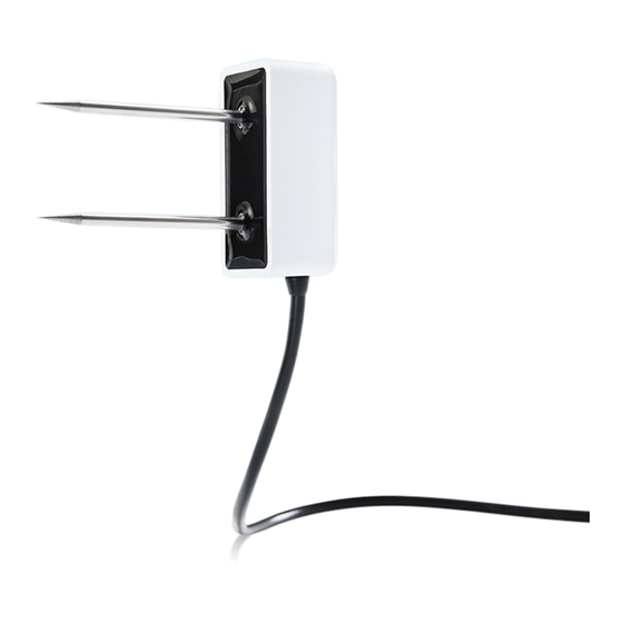
SySTEM 3. SySTEM This section reviews the components and functionality of the TEROS 10 sensor. 3.1 SpECIFICATIONS MEASUREMENT SpECIFICATIONS Volumetric Water Content (VWC) Range Mineral soil calibration 0.00–0.64 m Soilless media 0.0–0.7 m calibration Apparent dielectric 1 (air) to 80 (water) permittivity (ε... - Page 15 TEROS 10 pHySICAL SpECIFICATIONS Dimensions Length 5.1 cm (2.02 in) Width 2.4 cm (0.95 in) Height 7.5 cm (2.95 in) Needle Length 5.4 cm (2.11 in) Cable Length 5 m (standard) 40 m (maximum custom cable length) NOTE: Contact Customer Support if a nonstandard cable length is needed.
-
Page 16: Components
SySTEM COMpLIANCE Manufactured under ISO 9001:2015 EM ISO/IEC 17050:2010 (CE Mark) 2014/30/EU and 2011/65/EU EN61326-1:2013 and EN55022/CISPR 22 3.2 COMpONENTS The TEROS 10 sensors use an electromagnetic field to measure the apparent dielectric permittivity ( e ) of the surrounding medium. The sensor supplies a 70-MHz oscillating wave to the sensor needles, which charge according to the dielectric of the material. -
Page 17: Theory
TEROS 10 The TEROS 10 VWC measurement sensitivity is contained within a 430-mL volume roughly depicted in Figure 5. Please see the application note Measurement volume of METER volumetric water content sensors for testing protocol and more thorough analysis. 1 cm 2 cm... -
Page 18: Service
(metergroup.com/ soil-sensor-calibration). 4.1.1 MINERAL SOILS According to METER tests, a single calibration equation will generally suffice for most mineral soil types with ECs from 0 dS/m to 8 dS/m saturation extract. VWC () is given by Equation Θ m = 1.895×10... -
Page 19: Apparent Dielectric Permittivity
TEROS 10 learn about METER calibration service (calibrations performed for a standard fee), review the article on soil sensor calibration (metergroup.com/soil-sensor-calibration) or contact Customer Support. The calibration for several potting soils, perlite, and peat moss is shown in Equation × RAW ×... -
Page 20: Customer Support
NOTE: For TEROS 10 sensors purchased through a distributor, please contact the distributor directly for assistance. 4.4 TERMS AND CONDITIONS By using METER instruments and documentation, you agree to abide by the METER Group, Inc. USA Terms and Conditions. Please refer to metergroup.com/terms-conditions... -
Page 21: Reference
TEROS 10 REFERENCE Topp GC, David JL, and Annan AP. 1980. Electromagnetic determination of soil water content: Measurement in coaxial transmission lines. Water Resources Research 16(3): 574–582. -
Page 22: Index
10 See data logger theory 13 customer support 16 data loggers 7–8, 10 connect to METER logger 7 connect to non-METER logger 8–9 ferrite core about 12 installation 3 installation ferrite core 3 installation tool 2 methods 6–7... - Page 23 18242-00 6.30.2018 METER Group, Inc. USA 2365 NE Hopkins Court Pullman, WA 99163 T: +1.509-332-5600 F: +1.509.332.5158 E: info@metergroup.com W: www.metergroup.com © 2018 All Rights Reserved. Printed in USA.
Need help?
Do you have a question about the TEROS 10 and is the answer not in the manual?
Questions and answers