
Related Manuals for Ampcontrol IPD


Summary of Contents for Ampcontrol IPD
- Page 1 INTEGRATED PROTECTION RELAY User Manual Version: 14, September/2020 Designed and manufactured in Australia by Ampcontrol Pty Ltd...
- Page 2 The note symbol highlights key information. Please share these notes with other operators. ENVIRO The enviro (environmental) symbol highlights areas which may have an impact on the surrounding fauna and/or flora. Uncontrolled Copy - Refer to Ampcontrol Website for Latest Version Page 2 of 96...
- Page 3 IPDB014 Version 14 – SEP/2020 Copyright Notice The Ampcontrol relay described in this document is the property of AMPCONTROL PTY LTD. It is furnished under a license agreement and is to be used only in accordance with the terms of the agreement.
-
Page 4: Table Of Contents
6.11 RDM ...................... 32 6.12 PLC Interface ..................32 6.13 RTU ....................... 32 6.14 Start, MCI and Stop Inputs ..............32 7 REMOTE DISPLAY MODULE (RDM-D) ............33 Uncontrolled Copy - Refer to Ampcontrol Website for Latest Version Page 4 of 96... - Page 5 16 REMOTE DATA COMMUNICATIONS ............65 17 SERVICE, MAINTENANCE & DISPOSAL ............. 66 17.1 Equipment Service ................. 66 17.2 Equipment Maintenance ................ 66 17.3 Disposal ....................67 Uncontrolled Copy - Refer to Ampcontrol Website for Latest Version Page 5 of 96...
- Page 6 Figure 4.2: IPD System Block Diagram .............. 13 Figure 5.1: IPD Mounting Orientation ..............20 Figure 5.2: IPD Relay and Base Dimensional Details ......... 21 Figure 5.3: Optional RDM Installation Arrangement ..........22 Figure 5.4: RDM-D Dimensional Details ............. 22 Figure 5.5: 3.3kV CCMD Dimensional Details ............
-
Page 7: Version History
Version Release Date Changes First release of RTUs that were for use with the IPD. Earlier RTU versions (5 and below) are not certified for use with the IPD. Field trial firmware for the first of the “Blue” RTU-D3 hardware. -
Page 8: Safety And Other Warnings
2.1.1 Intended Use of Equipment The IPD is intended to be used as a part of the electrical protection system operating on outlets supplying underground mining machinery. Multiple protection functions, as listed in this document, are combined into a compact, plug-in unit, which can be easily changed out to minimise down time in the event of a problem with the relay. -
Page 9: Operational Restrictions And Limits
IPD USER MANUAL IPDB014 Version 14 – SEP/2020 2.2 Operational Restrictions and Limits The operational restrictions listed below must be understood before considering using the IPD within systems designed to ensure the safety of personnel. 2.2.1 Installation The selection, installation, commissioning and use of this protective... - Page 10 CAUTION! All ancillary equipment used with the IPD integrated protection relay should be as specified in the IPD Equipment List to ensure safe operation of the relay. CAUTION! Cleaning the controller may create an electrostatic hazard. Anti-static cleaning media must be used.
-
Page 11: Receiving And Storage
Equipment that is found to be damaged or has been modified away from its published specification must not be used. Please contact Ampcontrol if the equipment is suspected to be different than that ordered or if it does not match the published specifications. -
Page 12: Product Overview
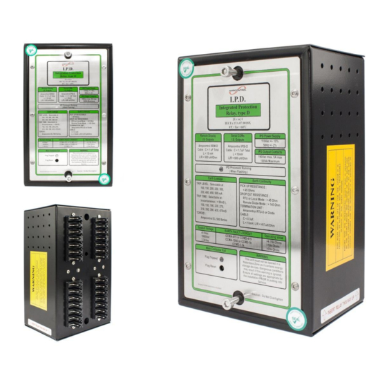
Remote Display Module (RDM) Figure 4.1: IPD Integrated Protection Relay The IPD relay mounts into the IPD Base Plate. All connections are made to the IPD Base Plate, allowing the relay to be changed out easily if required. The IPD relay has 5 Digital inputs, which feed into a microprocessor unit. The microprocessor has been... -
Page 13: Figure 4.2: Ipd System Block Diagram
The IPD Relay can provide machine communication through the use of a Remote Termination Unit (RTU-D) connected between the pilot and earth at the machine end of the trailing cable. The IPD’s protection parameters are automatically uploaded from the remote machine’s RTU-D when the cable is inserted into a power outlet. - Page 14 CTs to provide short circuit protection. The IPD can be set to open either its MCR output or CBR output when a short circuit trip is initiated. In typical installations the CBR output is used to trip a circuit breaker upstream from the outlet’s contactor.
-
Page 15: Accessories
The position of outlet’s contactor is monitored via the MCI input. The state of the contactor is then compared to the state of the IPD’s output relay. If the contactor is closed whilst the MCR is in the open position, a failed contactor trip will be initiated. - Page 16 4.2.4 Earth Leakage Toroid The IPD requires a summation toroid to be installed around the outlet’s three phase conductors. This toroid allows the IPD to measure the magnitude of outlet’s earth leakage current. Only one (1) earth leakage toroid is required per IPD.
- Page 17 IPDB014 Version 14 – SEP/2020 4.2.6 Remote Termination Unit Type D (RTU-D) (Optional) The RTU-D is an optional component in the IPD system. It is used to terminate the pilot cable in the motor enclosure instead of a diode. When used, the RTU-D stores the IPD’s Group 2 protection settings for that particular motor.
- Page 18 IPD’s earth fault lockout (EFLO) protection. This connection is made between the CCMD and the IPD, via a three (3) pole relay. The EFTM is connected between this relay and earth. To test the operation of the EFLO protection, the relay is held closed during an attempted start of the outlet.
-
Page 19: Installation
If modifications of any form are made to the IPD, the equipment may no longer be fit for use. If any modifications or damage to the IPD is evident, do not use the equipment and contact Ampcontrol for advice. -
Page 20: Mandatory Installation Practices
The installation is to be in accordance with the relevant installation Standards/Codes of Practice. Modifications must not be made to any part of the IPD. As supplied, the unit is built to, and complies with the relevant standards. Modifications to its construction will render the unit non- compliant. -
Page 21: Figure 5.2: Ipd Relay And Base Dimensional Details
Connections to the IPD Relay are made via a plug in base. This base is to be securely fastened to the enclosure in which it is being installed. The base is clearly labelled for ease of terminal location and identification. -
Page 22: Figure 5.3: Optional Rdm Installation Arrangement
However, if space restrictions preclude this, a compromise is to use one (1) RDM-D to monitor and control more than one IPD Relay. In these circumstances the following wiring arrangement is recommended:... -
Page 23: Figure 5.5: 3.3Kv Ccmd Dimensional Details
The Cable Connection Module (CCMD) is a resistor-diode barrier, which interfaces between the power circuit and the IPD Relay. It also provides an automatic High Voltage DC ‘Insulation Test’ following a successful Intrinsically Safe Earth Fault Lockout Test. The CCMD is housed in an encapsulated module. -
Page 24: Figure 5.6: 1Kv And 415V Ccmd Dimensional Details
This is not normally a problem with the current levels found in flameproof enclosure applications. To help avoid problems in other applications, select the smallest internal diameter CT, to suit the cable size. Uncontrolled Copy - Refer to Ampcontrol Website for Latest Version Page 24 of 96... -
Page 25: Figure 5.7: Earth Leakage Transformer Dimensional Details
4. Many small cables tend to be worse than say three large ones. Try to position the CT in the circuit with this in mind. There are two standard sizes of Earth Leakage Toroid that are permitted for use with the IPD Relay: a 60mm Inner Diameter and a 112mm Inner Diameter. -
Page 26: Figure 5.8: Current Transformer 45Mm I.d. (Part: 101272) Dimensional Details
IPD USER MANUAL IPDB014 Version 14 – SEP/2020 Figure 5.8: Current Transformer 45mm I.D. (Part: 101272) Dimensional Details Figure 5.9: Current Transformer 88mm I.D. (Part: 101703) Dimensional Details Uncontrolled Copy - Refer to Ampcontrol Website for Latest Version Page 26 of 96... -
Page 27: Electrical Installation Information
The IKD interface must be infallibly connected to the main system earth via at least one of the earthed mounting bolts on the chassis. The earth on pin 29 connects to the earth shield of the IPD Relay’s internal transformer. This earth is a protection earth and is not an intrinsic safety earth. -
Page 28: Table 1: Cable Recommendations: Intrinsically Safe Circuits
NOTE Wherever a screened cable is to be connected to Earth, ensure that the screen is earthed at ONE END ONLY, as near to the IPD as is practicable. Uncontrolled Copy - Refer to Ampcontrol Website for Latest Version... -
Page 29: Table 2: Cable Recommendations: Low Voltage Signal Circuits
Screen = Earth (Digital Input) * The IPD’s digital inputs could alternatively be run in a screened multi-core cable. (Separate cable for each IPD Relay in multiple installations.) Where these “low voltage” circuits need to connect near the power circuits (e.g. current transformers, cable connection module, main contactor auxiliaries etc.), care needs to be taken to ensure that the... - Page 30 IPDB014 Version 14 – SEP/2020 5.4.4 High Voltage Circuits The “high” voltage circuits of the IPD Relay are the 110VAC supply (pins 30, 31) and the relay contacts. Apart from keeping these separate from the other wiring to the relay there are no special requirements.
-
Page 31: Commissioning And Calibration
Disconnect the toroid from the IPD and ensure that a toroid fault trip is issued with similar effect. 6.3 Earth Fault Lockout Test the correct operation of Earth Fault Lockout protection by connecting test resistors on the relay side of the CCMD, per IPDE001. -
Page 32: Short Circuit Current Injection
LED is illuminated with each trip test conducted. 6.12 PLC Interface The correct operation of the PLC interface is determined by polling the IPD relay from either a PLC or a MODBUS capable PC, via the IPSI. -
Page 33: Remote Display Module (Rdm-D)
IPDB014 Version 14 – SEP/2020 7 REMOTE DISPLAY MODULE (RDM-D) The Ampcontrol RDM-D is the user interface for the IPD relay. The RDM-D consists of a two line, 16 character LCD display, LED status indicators and a tactile keypad. The display level is changed with the <UP> and <DOWN> arrow keys and the <LEFT> and <RIGHT>... -
Page 34: Trip / Status Messages
Voltage on load side of contactor is too low MC Close Fail MCI input did not close within 5 Sec of MCR relay closing IPD detected (via MCI input) that MC was opened – not External MC Open initiated by the IPD relay Insulation Alarm Test result at alarm level (1.5 x selected trip level) -
Page 35: Last Trip Status Messages
IPDB014 Version 14 – SEP/2020 7.2 Last Trip Status Messages The IPD Relay has several functions, which can stop/trip the outlet and then self-clear. The IPD Relay therefore saves the non-latched trip codes in a register and displays the ‘Last Trip’ messages in the Status Message Page. -
Page 36: Machine Communication
(See RTU-D General Case Dimensions, Drawing IPDA015 The Remote Termination Unit (RTU-D) provides remote stop, start facilities of the IPD Relay’s controlled outlet. The circuitry involved for these functions are self-diagnostic and will cause the outlet to turn off if the circuits are earthed or interconnected. -
Page 37: Machine Type Codes
There are 26 selectable machine type codes available for use in the Remote Termination Unit. The descriptive code is transmitted to the IPD Relay to identify the type of machine connected to the outlet. The codes are selected using the Remote Display Module (Level 9, Position 1). -
Page 38: Earth Protection Functions
Earth Continuity 9.1 Earth Leakage Protection The earth leakage protection function uses an Ampcontrol EL500 series toroid to measure the earth fault current. This function is tested to AS/NZS 2081.3 - 2002. A definite time operating characteristic is provided with adjustable trip sensitivity and an adjustable time delay. -
Page 39: Earth Fault Lockout Protection
The trip time for a CT detection fault has been fixed at 4 seconds in Version 5 of the IPD relay. This differs from earlier versions of the IPD firmware that derived the trip time from the Earth Leakage Time Delay setting. - Page 40 A cable connecting module, which is a resistive isolation device, is used to interface the power conductors to the IPD Relay. Modules are selected in the Group 1 Settings (Level 8, Position 3) for rated line voltages of 110V, 415V, 1000V or 3.3kV.
-
Page 41: Table 6: Insulation Test Trip Threshold And Alarm Level Comparison
Group 2 Settings Level 9, Position 15). The HV DC ‘Insulation Test’ is initiated when the IPD Relay closes its relay output RL4 for 2 seconds. This applies 110VAC to the CCMD Cable Connecting Module. A HV DC voltage is generated in the CCMD Module, which applies a voltage approaching the peak system voltage between each phase and earth. -
Page 42: Table 7: Insulation Test Accuracy With Respect To Trip Setting
Trip setting values of 10MΩ and 15MΩ aren’t specified above but are available for configuration within the software. These trip settings of 10MΩ and 15MΩ are not recommended for use by Ampcontrol. NOTE The start input must be held closed for the duration of the test. - Page 43 Only the <ENT> key is required to initiate the manual test. Mt:t The manual test is timing through the enabling period (3 seconds). Mt:A The manual test is Active. The display will show measured values. Uncontrolled Copy - Refer to Ampcontrol Website for Latest Version Page 43 of 96...
-
Page 44: Earth Continuity Protection
9.3.3 Setting the Parameters The IPD relay is configured to operate in either diode or RTU mode using the “Pilot Type” parameter, (Level 8, Position 1). This determines what terminating device the IPD expects to see on the pilot. -
Page 45: Current Related Functions
Phase Current Balance In addition to the above functions, IPD relays from Version 3 onwards have also had a Transient Overreach Compensation function implemented to compensate for spurious tripping from overreach at start-up. The IPD has a transient overreach performance figure of 35% (determined per IEC 60255-151, section 6.5.2). - Page 46 To reset a current related trip (excluding a short circuit trip), the following conditions must be met: a) The IPD reset input must be closed b) The trip accumulator must be less than 80% Uncontrolled Copy - Refer to Ampcontrol Website for Latest Version Page 46 of 96...
-
Page 47: Time Dependent Current Protection
If the selected current protection type is “vInv”, then a very inverse over-current characteristic set of curves are available for selection. The Very Inverse curve implemented in the IPD is equivalent to Curve B in Annex A of IEC 60255-151:... - Page 48 Typically, the capacity of a cold motor is given at six times its rated current. The IPD trip curves can be used to select the time multiplier, which best suits the motors overload capacity. While the main contactor is closed, the cooling output from the thermal model is calculated to achieve the necessary time constants.
-
Page 49: Short Circuit Protection
The “OC Trip” Accumulator shows the state of the thermal model: 0% = Cold, 100% = Trip. When a trip occurs the IPD Relay cannot be reset using the reset button until the accumulator is less than 80%. For the purposes of an emergency restart on a hot motor, the thermal memory can be reset by selecting Level 5, Position 3 on the Remote Display Module. -
Page 50: Phase Current Balance
Figure 10.2: Transient Overreach During Contactor Closure (Source: IEC 60255-151) Uncontrolled Copy - Refer to Ampcontrol Website for Latest Version Page 50 of 96... -
Page 51: Figure 10.3: Transient Overreach Protection Timing Diagram
Module: OFF, 40ms, 60ms, 80ms, 100ms or 120ms. When the START TRANSIENT mode is enabled, the IPD current setting is increased for the specified period of time, after the main contactor has been closed. The increased current is achieved by the following: 1. -
Page 52: Voltage Related Functions
IPDB014 Version 14 – SEP/2020 11 VOLTAGE RELATED FUNCTIONS The IPD relay uses the Cable Connection Module (CCMD/CCMA) to monitor the magnitude of the voltage on the load side of the outlet’s main contactor. The voltage measurement is used to implement the following functions: ... -
Page 53: Main Contactor Fail Protection
A main contactor fail trip causes the CBR relay to de-energise, which trips the circuit breaker. An internal battery backed flag in the IPD Relay is also tripped. A LED on the front panel of the IPD Relay begins to flash. -
Page 54: Fan Control
Remote Display Module - “Relay and Digital Input Status” Section (Level 6, Position 4). The outlet control in each IPD Relay has been designed so that an outlet will not run unless either: a) The FIR input is “ON”, or b) The Remote Termination Unit connected to that IPD has been programmed with machine type “iFan”. -
Page 55: Interlocking Sequence
12.2 Interlocking Sequence The fan interlocking operates as follows: 1. Each IPD powers up with the FID output turned off. At this point the FIR input on all IPD Relays will read, as off, therefore no outlet will run. 2. When a machine is plugged into an outlet that has its Remote Termination Unit programmed “iFan”... -
Page 56: User Adjustable Settings
Remote Termination Unit, depending on the “Pilot Mode” setting. Figure 13.1 shows how the memory is “switched”. If diode pilot mode is selected, the IPD Relay reads and writes to and from the relay’s internal memory for the Group 2 settings. -
Page 57: Table 8: Group 1 Settings
EL Sens Sets the sensitivity trip level for the earth leakage protection EFLO Selects the Cable Connection module to be used with the IPD Relay U/V Trip Selects the under-voltage trip threshold as a % of line volts Selects which output relay (MCR or CBR) is tripped in event of a... -
Page 58: Changing Parameter Settings
If the up or down keys are operated during the procedure the IPD Relay aborts the modifying sequence. When changes have been made to the stored values, the old value and the new value are stored in the event log. -
Page 59: Changing The Time & Date Settings
The date and time are used only to time stamp the events in the log (which are recorded sequentially regardless of the date/time). Date and time data is not used for any control functions. Uncontrolled Copy - Refer to Ampcontrol Website for Latest Version Page 59 of 96... -
Page 60: System Control
14 SYSTEM CONTROL 14.1 Inputs and Outputs 14.1.1 Digital Inputs The IPD Relay has five digital inputs, which are all voltage free contact inputs. Shorting the two input terminals together activates them. The inputs are: MCI – Main Contactor Position Feedback ... -
Page 61: Outlet Control
Both the remote and local stop buttons will turn off the outlet. WARNING! Stop/Start functions are operational only. Emergency stops must be wired directly into the pilot circuit. Uncontrolled Copy - Refer to Ampcontrol Website for Latest Version Page 61 of 96... -
Page 62: Operational Sequence
Once these conditions are obtained a cable fault lock out test is performed automatically. This takes 1 second. If the result of this test is satisfactory the IPD Relay goes into the run mode and the MCR relay picks up. -
Page 63: Event Log
IPDB014 Version 14 – SEP/2020 15 EVENT LOG A real time clock/calendar is included in the IPD Relay. This combines with the non-volatile memory to provide a data-logging feature. This log sequentially records the time, date and details of the most recent event. -
Page 64: Table 10: Event Log Identifiers And Descriptions
RTU Stop Stopping of the outlet by operation of the remote stop button MC Opened Main Contactor has opened but not initiated by the IPD Relay MC Fail Main Contactor Fail Function Trip Indicates that the MCI Input did not close within 5 seconds of MCR... -
Page 65: Remote Data Communications
IPDB014 Version 14 – SEP/2020 16 REMOTE DATA COMMUNICATIONS The IPD Integrated Protection Relay has the facility for connecting remote monitoring equipment. This can be in the form of either the Remote Display Module or other peripheral equipment such as PLC’s. -
Page 66: Service, Maintenance & Disposal
A number of external system based checks should be completed on a regular basis. These ‘routine inspections’ must be carried out by suitably trained people with knowledge of the IPD and the systems into which it is fitted. Routine inspections may take the form of either visual-only checks, or visual and ‘hands-on’... -
Page 67: Disposal
17.2.2 Internal Inspections Internal inspections are not permitted - do not open any of the IPD components. 17.2.3 Repair and Overhaul This is required every 4 years. The following components shall be returned to Ampcontrol for AS3800 inspection, repair and overhaul:- ... -
Page 68: Specifications
20, 40, 60, 80, 100, 120, 160ms Transient Delay Setting DISABLED, 40, 60, 80, 100, 120 Back EMF Timer Trip Delay Settings 2, 5, 10, 20 seconds Uncontrolled Copy - Refer to Ampcontrol Website for Latest Version Page 68 of 96... - Page 69 Selectable from 20% to 80% in 10% increments Trip Delay 800ms Serial Communications For information on Protocol and hardware requirements see DNET-IP2 Serial Communication System User Manual. Uncontrolled Copy - Refer to Ampcontrol Website for Latest Version Page 69 of 96...
-
Page 70: Equipment List
101703 CT 1000/1 88mm Inner Diameter OL2 (1000:1) REMOTE TERMINATION UNITS The IPD requires an RTU-D for its Machine Communication function. If this function is not required, than the RTU-D can be replaced with an appropriately rated diode. Part Number... - Page 71 Part Number Description 101826 EFTM 415/1kV IPC Earth/Fault Test 121170 EFTM 3.3kV IPC Earth/Fault Test 101296 Fuse Holder C/W 3A/660V Fuse 117139 Fuse 3A/660V (Spare Item) Uncontrolled Copy - Refer to Ampcontrol Website for Latest Version Page 71 of 96...
-
Page 72: Troubleshooting
20 TROUBLESHOOTING If a problem is experienced with the relay, use the following table to aid in fault finding. Should the fault persist, remove the relay and return the relay, plus a description of the fault, to Ampcontrol for repairs. NOTE Checking the Status page (level 0, position 0) should be the first step in troubleshooting. - Page 73 Time and date incorrect. Return to Ampcontrol for battery Low IS battery replacement and full testing. Resets to 1/01/9? on power up. Uncontrolled Copy - Refer to Ampcontrol Website for Latest Version Page 73 of 96...
-
Page 74: Appendix A: Drawings
3.3kV Cable Connecting Module – Dimensions & Marking Details IPDA020 110V Cable Connecting Module – Dimensions & Marking Details IPAA033 IPAA031 Relay Output Module PCB & Card Holder - General Arrangement Uncontrolled Copy - Refer to Ampcontrol Website for Latest Version Page 74 of 96... - Page 75 Ampcontrol Pty Ltd – ABN 28 000 915 542 IPD USER MANUAL IPDB014 Version 14 – SEP/2020 Uncontrolled Copy - Refer to Ampcontrol Website for Latest Version Page 75 of 96...
- Page 76 Ampcontrol Pty Ltd – ABN 28 000 915 542 IPD USER MANUAL IPDB014 Version 14 – SEP/2020 Uncontrolled Copy - Refer to Ampcontrol Website for Latest Version Page 76 of 96...
- Page 77 Ampcontrol Pty Ltd – ABN 28 000 915 542 IPD USER MANUAL IPDB014 Version 14 – SEP/2020 Uncontrolled Copy - Refer to Ampcontrol Website for Latest Version Page 77 of 96...
- Page 78 Ampcontrol Pty Ltd – ABN 28 000 915 542 IPD USER MANUAL IPDB014 Version 14 – SEP/2020 Uncontrolled Copy - Refer to Ampcontrol Website for Latest Version Page 78 of 96...
- Page 79 Ampcontrol Pty Ltd – ABN 28 000 915 542 IPD USER MANUAL IPDB014 Version 14 – SEP/2020 Uncontrolled Copy - Refer to Ampcontrol Website for Latest Version Page 79 of 96...
- Page 80 Ampcontrol Pty Ltd – ABN 28 000 915 542 IPD USER MANUAL IPDB014 Version 14 – SEP/2020 Uncontrolled Copy - Refer to Ampcontrol Website for Latest Version Page 80 of 96...
- Page 81 Ampcontrol Pty Ltd – ABN 28 000 915 542 IPD USER MANUAL IPDB014 Version 14 – SEP/2020 Uncontrolled Copy - Refer to Ampcontrol Website for Latest Version Page 81 of 96...
- Page 82 Ampcontrol Pty Ltd – ABN 28 000 915 542 IPD USER MANUAL IPDB014 Version 14 – SEP/2020 Uncontrolled Copy - Refer to Ampcontrol Website for Latest Version Page 82 of 96...
- Page 83 Ampcontrol Pty Ltd – ABN 28 000 915 542 IPD USER MANUAL IPDB014 Version 14 – SEP/2020 Uncontrolled Copy - Refer to Ampcontrol Website for Latest Version Page 83 of 96...
- Page 84 Ampcontrol Pty Ltd – ABN 28 000 915 542 IPD USER MANUAL IPDB014 Version 14 – SEP/2020 Uncontrolled Copy - Refer to Ampcontrol Website for Latest Version Page 84 of 96...
- Page 85 Ampcontrol Pty Ltd – ABN 28 000 915 542 IPD USER MANUAL IPDB014 Version 14 – SEP/2020 Uncontrolled Copy - Refer to Ampcontrol Website for Latest Version Page 85 of 96...
- Page 86 Ampcontrol Pty Ltd – ABN 28 000 915 542 IPD USER MANUAL IPDB014 Version 14 – SEP/2020 Uncontrolled Copy - Refer to Ampcontrol Website for Latest Version Page 86 of 96...
- Page 87 Ampcontrol Pty Ltd – ABN 28 000 915 542 IPD USER MANUAL IPDB014 Version 14 – SEP/2020 Uncontrolled Copy - Refer to Ampcontrol Website for Latest Version Page 87 of 96...
- Page 88 Ampcontrol Pty Ltd – ABN 28 000 915 542 IPD USER MANUAL IPDB014 Version 14 – SEP/2020 Uncontrolled Copy - Refer to Ampcontrol Website for Latest Version Page 88 of 96...
- Page 89 Ampcontrol Pty Ltd – ABN 28 000 915 542 IPD USER MANUAL IPDB014 Version 14 – SEP/2020 Uncontrolled Copy - Refer to Ampcontrol Website for Latest Version Page 89 of 96...
- Page 90 Ampcontrol Pty Ltd – ABN 28 000 915 542 IPD USER MANUAL IPDB014 Version 14 – SEP/2020 Uncontrolled Copy - Refer to Ampcontrol Website for Latest Version Page 90 of 96...
- Page 91 Ampcontrol Pty Ltd – ABN 28 000 915 542 IPD USER MANUAL IPDB014 Version 14 – SEP/2020 Uncontrolled Copy - Refer to Ampcontrol Website for Latest Version Page 91 of 96...
- Page 92 Ampcontrol Pty Ltd – ABN 28 000 915 542 IPD USER MANUAL IPDB014 Version 14 – SEP/2020 Uncontrolled Copy - Refer to Ampcontrol Website for Latest Version Page 92 of 96...
- Page 93 Ampcontrol Pty Ltd – ABN 28 000 915 542 IPD USER MANUAL IPDB014 Version 14 – SEP/2020 Uncontrolled Copy - Refer to Ampcontrol Website for Latest Version Page 93 of 96...
-
Page 94: Appendix B: Additional Information On Current Protection
(the threshold of independent time operation) is made redundant by the independent time characteristic of the IPD’s short circuit protection, which has a maximum setting of 10 times G NOTE: the function which has been published elsewhere in this document for Over Current is: ... - Page 95 Motor Overload – IEC60255-8 See “m-OL” Curves (Drawing IPDB019) and Motor Overload Functional Block Diagram (Drawing IPDB035) in Appendix A – Drawings. The Ampcontrol IPD implements the motor thermal model in line with IEC 60255 Part 8, represented by two curves: ...
- Page 96 IPDB014 Version 14 – SEP/2020 Also, 1800 Where: m is the time multiplier setting, programmed in the IPD menu. After a trip occurs, the thermal time constant is modified by the cooling modifier: cold...
Need help?
Do you have a question about the IPD and is the answer not in the manual?
Questions and answers