
Related Manuals for Ampcontrol IPM V2


Summary of Contents for Ampcontrol IPM V2
- Page 1 IPM V2 INTEGRATED PROTECTION RELAY User Manual Revision: 15, May 2018 Designed and manufactured in Australia by Ampcontrol Pty Ltd...
- Page 2 The note symbol highlights key information. Please share these notes with other operators. ENVIRO The enviro (environmental) symbol highlights areas which may have an impact on the surrounding fauna and/or flora. Uncontrolled Copy - Refer to Ampcontrol Website for Latest Version Page 2 of 83...
- Page 3 IPM2B003 Revision 15 – MAY/18 Copyright Notice The Ampcontrol relay described in this document is the property of AMPCONTROL PTY LTD. It is furnished under a license agreement and is to be used only in accordance with the terms of the agreement.
-
Page 4: Table Of Contents
7 CURRENT RELATED FUNCTIONS ..............36 7.1 Overload Protection ................. 37 7.2 Short Circuit Protection ................38 7.3 Phase Current Balance ................38 7.4 Residual Current Signal ................39 Uncontrolled Copy - Refer to Ampcontrol Website for Latest Version Page 4 of 83... - Page 5 Tripping Curves for Instantaneous Trip Time Setting ........65 Tripping Curves for 25mA Trip Level Setting ..........65 APPENDIX 2: IPM Full Load Current Selection Table (100:1 CT) ...... 66 Uncontrolled Copy - Refer to Ampcontrol Website for Latest Version Page 5 of 83...
- Page 6 APPENDIX 3: IPM Full Load Current Selection Table (1000:1 CT) ....67 APPENDIX 4: IPM Menu Structure ..............68 APPENDIX 5: IPM Modbus Address Table ............70 APPENDIX 6: Drawings ..................74 Uncontrolled Copy - Refer to Ampcontrol Website for Latest Version Page 6 of 83...
- Page 7 Figure 6.4: Earth Continuity Connections ..................34 Figure 7.1: IPM Phase CT Connections ..................36 Figure 8.1: IPM Voltage Monitoring Connections ................ 40 Figure 12.1: IPM Relay Fascia and Display................. 45 Uncontrolled Copy - Refer to Ampcontrol Website for Latest Version Page 7 of 83...
- Page 8 Table 6: Modbus Exception ......................49 Table 7: Modbus Status ......................50 Table 8: Events ........................... 56 Table 9: User Adjustable Settings ....................58 Table 10: User Adjustable Settings ..................... 59 Uncontrolled Copy - Refer to Ampcontrol Website for Latest Version Page 8 of 83...
-
Page 9: Safety And Other Warnings
As safety depends on the relay functioning correctly it is highly recommended that all safety functions of the relay be periodically tested to ensure correct operation. Uncontrolled Copy - Refer to Ampcontrol Website for Latest Version Page 9 of 83... -
Page 10: Receiving And Storage
Equipment that is found to be damaged or has been modified away from its published specification must not be used. Please contact Ampcontrol if the equipment is suspected to be different than that ordered or if it does not match the published specifications. -
Page 11: Product Overview
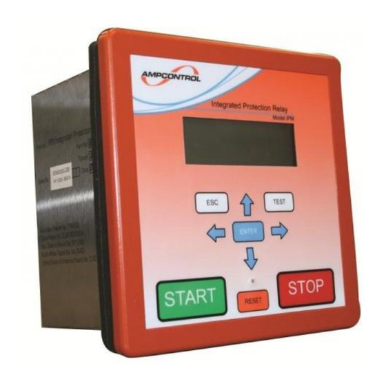
3 PRODUCT OVERVIEW 3.1 IPM V2 Relay The Ampcontrol IPM V2 Integrated Protection Relay is an intelligent protection relay based on microprocessor technology. The IPM Integrated Relay provides the necessary functions required for protecting electrical outlets supplying underground mining machinery, powered by reeling or trailing cables, in the metalliferous industry. -
Page 12: Figure 3.2: Ipm Block Diagram
Inputs Alarm Output Relay CBR Output Relay MCR Output Relay 1 Pilot MCR Output Relay 2 Diode (Optional) (Alternative) Pilot Termination Figure 3.2: IPM Block Diagram Uncontrolled Copy - Refer to Ampcontrol Website for Latest Version Page 12 of 83... - Page 13 In addition to the overload protection functions, the IPM relay uses the currents measured from the three phase CTs to provide short circuit protection. The IPM opens its CBR output when a short circuit Uncontrolled Copy - Refer to Ampcontrol Website for Latest Version Page 13 of 83...
-
Page 14: Accessories
45mm inner diameter (1000:1 & 500:5) and 88mm inner diameter (1000:1 only). The current transformers are panel mounted units. Figure 3.4: Phase Current Transformers Uncontrolled Copy - Refer to Ampcontrol Website for Latest Version Page 14 of 83... -
Page 15: Figure 3.5: Earth Leakage Toroid
IPM‟s protection settings. The RTM also offers a remote start input. Figure 3.6: Remote Termination Module Uncontrolled Copy - Refer to Ampcontrol Website for Latest Version Page 15 of 83... -
Page 16: Installation
It is extremely important that the limitations and functionality of the relay are understood to prevent incorrect installation and use from creating a potentially dangerous risk. If in doubt as to the nature of the limitations or their implication, consult a competent authority such as a supervisor or Ampcontrol technical representative. -
Page 17: Mechanical Installation Information
The screws are inserted into the bracket and tightened to secure the IPM to the panel. Figure 4.1: IPM Relay Dimensions Uncontrolled Copy - Refer to Ampcontrol Website for Latest Version Page 17 of 83... -
Page 18: Figure 4.2: Ipm Relay Rear Panel Details
The IPM uses a 1000:1 current transformer installed around all three phases to monitor the earth leakage current of the outlet. These current transformers are panel mounted. Figure 4.3: Current Transformer 45mm I.D. (Part: 101272) Dimensional Details Uncontrolled Copy - Refer to Ampcontrol Website for Latest Version Page 18 of 83... -
Page 19: Figure 4.4: Current Transformer 88Mm I.d. (Part: 101703) Dimensional Details
IPM V2 USER MANUAL IPM2B003 Revision 15 – MAY/18 Figure 4.4: Current Transformer 88mm I.D. (Part: 101703) Dimensional Details 4.3.3 Remote Termination Module (RTM) Figure 4.5: RTM Dimensions Uncontrolled Copy - Refer to Ampcontrol Website for Latest Version Page 19 of 83... -
Page 20: Electrical Installation Information
Alarm Output Relay CBR Output Relay MCR Output Relay 1 Pilot MCR Output Relay 2 Diode (Optional) (Alternative) Pilot Termination Figure 4.6: IPM Connection Block Diagram Uncontrolled Copy - Refer to Ampcontrol Website for Latest Version Page 20 of 83... -
Page 21: Figure 4.7: Ipm Relay Electrical Connections: Digital Inputs
If the IPM is to be installed in areas of high electrical interference, it is recommended that the wiring for the digital inputs be run in screened cables. Uncontrolled Copy - Refer to Ampcontrol Website for Latest Version Page 21 of 83... -
Page 22: Figure 4.8: Ipm Relay Electrical Connections: Phase Current Transformers
5. Select the smallest internal diameter CT to suit the cable size. NOTE The two CT-COM terminals (12 & 13) are internally connected and are joined to earth. Uncontrolled Copy - Refer to Ampcontrol Website for Latest Version Page 22 of 83... -
Page 23: Figure 4.9: Ipm Relay Electrical Connections: Earth Leakage Toroid
The earth leakage protection function can be tested by connecting an AC supply through the earth leakage toroid, via a test pushbutton and a resistor. The resistor must be selected to ensure that the earth leakage protection trips as required. Uncontrolled Copy - Refer to Ampcontrol Website for Latest Version Page 23 of 83... -
Page 24: Figure 4.10: Ipm Relay Electrical Connections: Earth Leakage Toroid
A normally closed contact with a contact monitoring block should be considered. NOTE Remote Start is not available if the IPM is used in Diode Mode. Uncontrolled Copy - Refer to Ampcontrol Website for Latest Version Page 24 of 83... -
Page 25: Figure 4.11: Ipm Relay Electrical Connections: Itm
25 of the IPM relay. 4.4.8 Terminal 26 Do not connect. This terminal is unused in this version of the IPM relay. Uncontrolled Copy - Refer to Ampcontrol Website for Latest Version Page 25 of 83... -
Page 26: Figure 4.13: Ipm Relay Electrical Connections: Analogue Output
The Circuit Breaker Relay (CBR) is intended to provide a back-trip to an upstream circuit breaker for faults such as frozen contactor and short circuit. Uncontrolled Copy - Refer to Ampcontrol Website for Latest Version Page 26 of 83... -
Page 27: Figure 4.15: Ipm Relay Electrical Connections: Power Supply
The earth connection on the rear of the IPM relay is a bolted connection. An earth conductor should be secured to the chassis of the IPM using a ring lug. Uncontrolled Copy - Refer to Ampcontrol Website for Latest Version Page 27 of 83... -
Page 28: Commissioning And Calibration
5.6 Current Detection in CTs Ensure the integrity of the current-detection CTs by injecting primary current into the CT aperture and validating the reading on the IPM screen. Uncontrolled Copy - Refer to Ampcontrol Website for Latest Version Page 28 of 83... -
Page 29: Main Contactor Fail (Mcf)
5.11 Lock, Reset, Aux, Ex-Stop, Ex-Start & MCI Inputs Ensure that the digital inputs to the IPM are operating correctly by operating each of the inputs and ensuring that the IPM functions as expected. Uncontrolled Copy - Refer to Ampcontrol Website for Latest Version Page 29 of 83... -
Page 30: Earth Protection Functions
IPM V2 and assess how the relay‟s performance compares with the requirements of AS/NZS 2081. Testing was completed to assess the ability of the IPM V2 relay to trip within acceptable levels. The results for the earth leakage tripping times of the relay are detailed in APPENDIX 1: IPM Earth Leakage Tripping Curves. -
Page 31: Insulation Test
The ITM is the preferred isolation module and must be used when the „Insulation Test‟ function is required. When “None” is selected the IPM Relay does not provide „Insulation Test‟, or voltage functions. Uncontrolled Copy - Refer to Ampcontrol Website for Latest Version Page 31 of 83... -
Page 32: Figure 6.3: Itm Insulation Test Connections
L3: Indicates the status of the insulation test. L4: Displays the insulation resistance as a result of the test and is retained in memory until the next test is carried out. Uncontrolled Copy - Refer to Ampcontrol Website for Latest Version Page 32 of 83... - Page 33 The status of the manual insulation test is shown on the Insulation Test Screen (Level 3, Screen 2). The three functions shown on the screen are „Not Active‟, „Arming Man.Ins.Test‟ and „Manual Insulat. Test‟. The display will show the last measured value. Uncontrolled Copy - Refer to Ampcontrol Website for Latest Version Page 33 of 83...
-
Page 34: Earth Continuity
- earth loop resistance is less than 45Ω. The selection is either „EC Trip Latch: On‟ or „Off” (Level 6, Screen 17). To manually reset the relay, operate the reset button. Uncontrolled Copy - Refer to Ampcontrol Website for Latest Version Page 34 of 83... - Page 35 EL current that does not cause a nuisance tripping. Similarly, the earth continuity trip time should be as low as practical to not cause a nuisance trips. In low noise applications (eg: simple DOL motors Uncontrolled Copy - Refer to Ampcontrol Website for Latest Version Page 35 of 83...
-
Page 36: Current Related Functions
Where EC trip settings above 200ms are required to avoid nuisance tripping Ampcontrol recommends the source of noise (and so the electrical distribution system design) is properly investigated to ensure the system is safe. -
Page 37: Overload Protection
An emergency restart on a hot motor can be achieved by zeroing the thermal accumulator memory. This is done by closing the Lock input and Reset key/digital input simultaneously for 1.5 seconds. Uncontrolled Copy - Refer to Ampcontrol Website for Latest Version Page 37 of 83... -
Page 38: Short Circuit Protection
If any phase drops below the selected trip setting for a period of 2 seconds then the outlet is stopped. To reset the relay following a current balance trip, operate the reset key/digital input. Cur: Uncontrolled Copy - Refer to Ampcontrol Website for Latest Version Page 38 of 83... -
Page 39: Residual Current Signal
This function is used when in snore mode and must be set to an appropriate level – note that there is a 4 second delay before a trip. Uncontrolled Copy - Refer to Ampcontrol Website for Latest Version Page 39 of 83... -
Page 40: Voltage Related Functions
The trip level is selected via the „U/V Trp level‟ setting (Level 6, Screen 19) and is adjustable between 40, 50, 60, 70, 75, 80, 85, 90, 95 & OFF. Setting the trip level to „OFF‟ disables this function. Uncontrolled Copy - Refer to Ampcontrol Website for Latest Version Page 40 of 83... -
Page 41: Voltage Metering
Line voltages of 415V and 1000V are configured when the appropriate Insulation Test Module is selected in the „Group 1 Settings‟ (Level 5, Screen 2). Uncontrolled Copy - Refer to Ampcontrol Website for Latest Version Page 41 of 83... -
Page 42: Machine Communication
9.3 Machine Type Number Machine numbers 1 to 40 can be assigned to machines. These numbers are programmed at the „RTM Mach. Num.‟ page (Level 6, Screen 2). Uncontrolled Copy - Refer to Ampcontrol Website for Latest Version Page 42 of 83... -
Page 43: Fan Burp Function
Mode when power is restored. If Aux is open, or there is an EL fault on Power Up, the snore function will wait for up to 15 seconds to start. Uncontrolled Copy - Refer to Ampcontrol Website for Latest Version Page 43 of 83... -
Page 44: Setup Procedure For Snore Function
The Message „Snore – Need Aux‟ will be displayed on the screen when in Snore mode with the AUX open. This will reset the snore delay timer. Uncontrolled Copy - Refer to Ampcontrol Website for Latest Version Page 44 of 83... -
Page 45: Product Operation
The Status LED is a single bi-coloured LED that can be viewed some distance from the relay. Status indication is as follows: Table 2: Status Indication IPM Status LED Colour LED Flash OK (Run) Green OK (Stopped) Green Alarm Trip Uncontrolled Copy - Refer to Ampcontrol Website for Latest Version Page 45 of 83... -
Page 46: Trip/Status Messages
MCI input fails to follow MCR relay output during burp phase Under Current Trip Under Current function tripped Shows „Last Trip‟ record Last T:-------- OTS Mode Exit Stop IPM has exited the OTS Test Mode Uncontrolled Copy - Refer to Ampcontrol Website for Latest Version Page 46 of 83... - Page 47 Main Contactor Fail Main Contactor Fail function tripped RTM-Offline Trip IPM cannot communicate with RTM IPM Memory Error (see Corrupted memory in relay‟s stored settings Note 1) Uncontrolled Copy - Refer to Ampcontrol Website for Latest Version Page 47 of 83...
-
Page 48: Last Trip Status Messages
E/C Ohms Trip that provides additional EC Ω Trip information for E/C Trip Main contactor opened – opening not initiated MC Opened by the IPM Relay Uncontrolled Copy - Refer to Ampcontrol Website for Latest Version Page 48 of 83... -
Page 49: Communications
Currently, only the first 78 registers contain valid data. Supported Modbus exception responses are: Table 6: Modbus Exception Modbus Exception Comment Illegal Function Illegal Data Address Illegal Data Value Uncontrolled Copy - Refer to Ampcontrol Website for Latest Version Page 49 of 83... -
Page 50: Remote Ipm Control
When remote start is active, the remote input is closed to start the IPM and must remain closed while the IPM is running. The remote input is opened to stop the IPM. Uncontrolled Copy - Refer to Ampcontrol Website for Latest Version Page 50 of 83... - Page 51 2. Start mode - „Modbs‟ and „Snore‟ These modes will not operate when remote start is set to „yes‟. The status display will show “Configuration Err”. Uncontrolled Copy - Refer to Ampcontrol Website for Latest Version Page 51 of 83...
- Page 52 IPM to run and then a local stop is used to stop the IPM. Because of the edged triggered nature of the RTM digital input, the IPM will not automatically restart. Uncontrolled Copy - Refer to Ampcontrol Website for Latest Version Page 52 of 83...
-
Page 53: System Control
L3: Displays the status of Alarm Relay, the Test key and the Main Contactor input. L4: Displays the status of the Start, Reset and Stop Keys. Uncontrolled Copy - Refer to Ampcontrol Website for Latest Version Page 53 of 83... - Page 54 IPM will cycle through the following start sequence: testing, run, stopped, pause then repeat the sequence while ever the start input is closed. Uncontrolled Copy - Refer to Ampcontrol Website for Latest Version Page 54 of 83...
-
Page 55: Analogue Output
The alarm message is displayed until a new test is initiated or the <ENT> key is pressed while displaying the alarm message. The „Insulat. Test Alarm‟ is also recorded in the Event Log. Uncontrolled Copy - Refer to Ampcontrol Website for Latest Version Page 55 of 83... -
Page 56: Event Log
Records that set up data has been modified Und.I Trp Under Current Trip caused outlet to stop uvolt trp Records that voltage was not present on at least Uncontrolled Copy - Refer to Ampcontrol Website for Latest Version Page 56 of 83... -
Page 57: Time And Date
Press the ENTER key. The “v” now changes to a “?” The right arrow key is used to increment the allowable values, once the desired value is obtained, press the ENTER key again. The “?” returns to a “v”. Uncontrolled Copy - Refer to Ampcontrol Website for Latest Version Page 57 of 83... -
Page 58: User Adjustable Settings
If Diode Mode is selected the IPM Relay reads and writes to and from the relay‟s internal memory for the group 2 settings. If RTM Mode is selected, the settings are sent to and retrieved from the memory in the Remote Termination Module. Uncontrolled Copy - Refer to Ampcontrol Website for Latest Version Page 58 of 83... -
Page 59: Table 10: User Adjustable Settings
Sets the burp pulse on time Burp Off Time Sets the burp pulse off time 4-20mA Output Sets the value to be transmitted Snore Delay Sets the Snore Delay Value Uncontrolled Copy - Refer to Ampcontrol Website for Latest Version Page 59 of 83... -
Page 60: Changing Settings
When changes have been made to the stored values, the old value and the new value are stored in the event log. A separate log immediately proceeds this, recording the time and date that the change was made. Uncontrolled Copy - Refer to Ampcontrol Website for Latest Version Page 60 of 83... -
Page 61: Service, Maintenance & Disposal
Verify all electrical connections are secure with no loose screw terminals or DIN rail terminals not fitted to rails etc. Uncontrolled Copy - Refer to Ampcontrol Website for Latest Version Page 61 of 83... -
Page 62: Equipment Maintenance
WARNING! All repairs must be carried out by Ampcontrol only. If a fault develops, return the product to Ampcontrol for repair. It is essential that no attempt be made to repair the product as any attempt to dismantle or repair the product can seriously compromise the safety of the unit and voids product warranty. -
Page 63: Specifications
Residual Current OFF, 10%, 20%, 30%, 40%, 50%, 60%, 80%, 100%, 120%, 150%, Trip Setting 200%, 250% Trip Time OFF, 100ms, 200ms, 500ms, 1sec, 2, 3, 5sec Uncontrolled Copy - Refer to Ampcontrol Website for Latest Version Page 63 of 83... -
Page 64: Equipment List
RTM Remote Termination Module 101703 88mm Earth leakage Toroid 141548 Current Transformer 100:1 [500:5] 45mm I.D. 101272 Current Transformer 1000:1 45mm I.D. 101108 40mm M5 Screw 171010 Support Bracket Uncontrolled Copy - Refer to Ampcontrol Website for Latest Version Page 64 of 83... -
Page 65: Appendix 1: Ipm Earth Leakage Tripping Curves
The graph below shows the relay trip times for a 25mA trip level setting, for different trip time settings. INST 50ms 100ms 150ms 1000 Fault Current (mA) NOTE Similar graphs can be obtained for 50mA, 100mA, 200mA and 500mA trip levels. Uncontrolled Copy - Refer to Ampcontrol Website for Latest Version Page 65 of 83... -
Page 66: Appendix 2: Ipm Full Load Current Selection Table (100:1 Ct)
28.8 57.6 0.9250 1.850 3.70 14.8 29.6 59.2 0.9500 1.900 3.80 15.2 30.4 60.8 0.9750 1.950 3.90 15.6 31.2 62.4 1.0000 2.000 4.00 16.0 32.0 64.0 Uncontrolled Copy - Refer to Ampcontrol Website for Latest Version Page 66 of 83... -
Page 67: Appendix 3: Ipm Full Load Current Selection Table (1000:1 Ct)
16.00 32.0 8.250 16.50 33.0 8.500 17.00 34.0 8.750 17.50 35.0 9.000 18.00 36.0 9.250 18.50 37.0 9.500 19.00 38.0 9.750 19.50 39.0 10.000 20.00 40.0 Uncontrolled Copy - Refer to Ampcontrol Website for Latest Version Page 67 of 83... -
Page 68: Appendix 4: Ipm Menu Structure
[ 1 to 40 ] Num. [5.125A – 625A] 100% Current 5.125A Short Cct.Trp [Selectable; 3.0 to 10 Times FLC] 3.0 x Short Cct.t [20, 40, 60,80,100, 120, 160 mSec] Uncontrolled Copy - Refer to Ampcontrol Website for Latest Version Page 68 of 83... -
Page 69: Uncontrolled Copy - Refer To Ampcontrol Website For Latest Version
Last Trip Message Ext.Stop Burp: MCR - Open Earth Leakage Alarm I Balance Trip Running UnderVoltage Alarm Residual Cur. Trip Snore Insulat.Test Alarm Main Contactor Fail Uncontrolled Copy - Refer to Ampcontrol Website for Latest Version Page 69 of 83... -
Page 70: Appendix 5: Ipm Modbus Address Table
5 = Config Error A Phase Voltage volts_a 6 = OTS Test Mode (0…120%) 7 = Spare B Phase Voltage volts_b (0…120%) C Phase Voltage volts_c (0…120%) Uncontrolled Copy - Refer to Ampcontrol Website for Latest Version Page 70 of 83... -
Page 71: Uncontrolled Copy - Refer To Ampcontrol Website For Latest Version
13 = 19200 Even Parity 5 = 100 ms 14 = 19200 Odd Parity 6 = 120 ms 15 = 19200 No Parity 7 = 160 ms Uncontrolled Copy - Refer to Ampcontrol Website for Latest Version Page 71 of 83... -
Page 72: Uncontrolled Copy - Refer To Ampcontrol Website For Latest Version
8 = 88% 1 = 1.0M 9 = 96% 2 = 2.0M meg_level 10 = OFF 3 = 5.0M 4 = 10M 5 = 20M 6 = None Uncontrolled Copy - Refer to Ampcontrol Website for Latest Version Page 72 of 83... -
Page 73: Uncontrolled Copy - Refer To Ampcontrol Website For Latest Version
9 = 96% 9 = 30F 10 = Off 10 = 60F RCD Reset Lock 0 = Invalid Data RCD_rst_lock 1 = OFF 2 = ON 77-78 Reserved Uncontrolled Copy - Refer to Ampcontrol Website for Latest Version Page 73 of 83... -
Page 74: Appendix 6: Drawings
IPM 415V ITM Dimension & Marking Details IPM2A003 IPM 1kV ITM Dimension & Marking Details IPM2A005 IPM RTM Remote Termination Module Dimension & Marking Details IPM2A018 IPM Relay Current TXF Profiles Uncontrolled Copy - Refer to Ampcontrol Website for Latest Version Page 74 of 83... -
Page 75: Uncontrolled Copy - Refer To Ampcontrol Website For Latest Version
Ampcontrol Pty Ltd – ABN 28 000 915 542 IPM V2 USER MANUAL IPM2B003 Revision 15 – MAY/18 Uncontrolled Copy - Refer to Ampcontrol Website for Latest Version Page 75 of 83... -
Page 76: Uncontrolled Copy - Refer To Ampcontrol Website For Latest Version
Ampcontrol Pty Ltd – ABN 28 000 915 542 IPM V2 USER MANUAL IPM2B003 Revision 15 – MAY/18 Uncontrolled Copy - Refer to Ampcontrol Website for Latest Version Page 76 of 83... -
Page 77: Uncontrolled Copy - Refer To Ampcontrol Website For Latest Version
Ampcontrol Pty Ltd – ABN 28 000 915 542 IPM V2 USER MANUAL IPM2B003 Revision 15 – MAY/18 Uncontrolled Copy - Refer to Ampcontrol Website for Latest Version Page 77 of 83... -
Page 78: Uncontrolled Copy - Refer To Ampcontrol Website For Latest Version
Ampcontrol Pty Ltd – ABN 28 000 915 542 IPM V2 USER MANUAL IPM2B003 Revision 15 – MAY/18 Uncontrolled Copy - Refer to Ampcontrol Website for Latest Version Page 78 of 83... -
Page 79: Uncontrolled Copy - Refer To Ampcontrol Website For Latest Version
Ampcontrol Pty Ltd – ABN 28 000 915 542 IPM V2 USER MANUAL IPM2B003 Revision 15 – MAY/18 Uncontrolled Copy - Refer to Ampcontrol Website for Latest Version Page 79 of 83... -
Page 80: Uncontrolled Copy - Refer To Ampcontrol Website For Latest Version
Ampcontrol Pty Ltd – ABN 28 000 915 542 IPM V2 USER MANUAL IPM2B003 Revision 15 – MAY/18 Uncontrolled Copy - Refer to Ampcontrol Website for Latest Version Page 80 of 83... -
Page 81: Uncontrolled Copy - Refer To Ampcontrol Website For Latest Version
Ampcontrol Pty Ltd – ABN 28 000 915 542 IPM V2 USER MANUAL IPM2B003 Revision 15 – MAY/18 Uncontrolled Copy - Refer to Ampcontrol Website for Latest Version Page 81 of 83... -
Page 82: Uncontrolled Copy - Refer To Ampcontrol Website For Latest Version
Ampcontrol Pty Ltd – ABN 28 000 915 542 IPM V2 USER MANUAL IPM2B003 Revision 15 – MAY/18 Uncontrolled Copy - Refer to Ampcontrol Website for Latest Version Page 82 of 83... -
Page 83: Uncontrolled Copy - Refer To Ampcontrol Website For Latest Version
Ampcontrol Pty Ltd – ABN 28 000 915 542 IPM V2 USER MANUAL IPM2B003 Revision 15 – MAY/18 Uncontrolled Copy - Refer to Ampcontrol Website for Latest Version Page 83 of 83...
Need help?
Do you have a question about the IPM V2 and is the answer not in the manual?
Questions and answers