Table of Contents
Advertisement
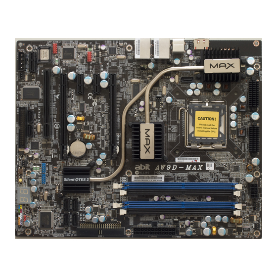
AW9D-MAX
AW9D
Motherboard
Socket 775
Intel Core 2 Duo (Extreme Edition)
Intel Pentium Extreme Edition
Intel Pentium D
Intel Pentium 4
User's Manual
About this Manual:
This user's manual contains all the information you may
need for setting up this motherboard. To read the user's
manual of PDF format (readable by
the "Driver & Utility CD" into the CD-ROM drive in your
system. The auto-run screen will appear, click the
"Manual" tab to enter its submenu. If not, browse the
root directory of the CD-ROM via the File Manager, and
double click the "AUTORUN" file.
Adobe
Reader), place
LGA775 ATX Motherboard
Intel 975X / ICH7R
1066MHz FSB
Dual DDR2 800
Dual PCI-E X16 Graphics Slots
Dual GbE LAN (AW9D-MAX)
8x SATA 3Gb/s (AW9D-MAX)
IEEE 1394 (AW9D-MAX)
HD 7.1 Audio
Silent OTES™ Technology
uGuru™ Technology
Advertisement
Table of Contents

Related Manuals for Abit AW9-D


Summary of Contents for Abit AW9-D
- Page 1 User’s Manual About this Manual: This user’s manual contains all the information you may need for setting up this motherboard. To read the user’s manual of PDF format (readable by Adobe the “Driver & Utility CD” into the CD-ROM drive in your system.
-
Page 2: Aw9D-Max, Aw9D
No part of this manual may be reproduced, transmitted or transcribed without the expressed written permission of the manufacturer and authors of this manual. If you do not properly set the motherboard settings, causing the motherboard to malfunction or fail, we cannot guarantee any responsibility. -
Page 3: Table Of Contents
1.2.1 AW9D-MAX...1-3 1.2.2 AW9D ...1-4 2. Hardware Setup ... 2-1 2.1 Choosing a Computer Chassis ...2-1 2.2 Installing Motherboard ...2-1 2.3 Checking Jumper Settings ...2-2 2.3.1 CMOS Memory Clearing Header and Backup Battery ...2-3 2.3.2 Wake-up Header ...2-5 2.4 Connecting Chassis Components...2-6 2.4.1 ATX Power Connectors ...2-6... - Page 4 5.1 POST Code Definitions ...5-1 5.1.1 AWARD POST Code Definitions...5-1 5.1.2 AC2005 POST Code Definitions...5-4 5.2 Troubleshooting (How to Get Technical Support?) ...5-5 5.2.1 Q & A ...5-5 5.2.2 Technical Support Form ...5-8 5.2.3 Universal ABIT Contact Information ...5-9 AW9D-MAX, AW9D...
-
Page 5: Introduction
“AW9D-MAX” only) • Onboard PCI-E Gigabit LAN controller supports 10/100/1000Mb Ethernet (For model “AW9D” only) Audio • ABIT AudioMAX HD 7.1 CH • Supports auto jack sensing and optical S/PDIF In/Out • Dolby Master Studio Certificated Expansion Slots • 2x PCI-E X16 slots •... - Page 6 • Supports 2 Ports IEEE 1394 at 400Mb/s transfer rate ABIT Engineered ™ • ABIT uGuru Technology • ABIT Silent OTES • ABIT AudioMAX Technology Miscellaneous • ATX form factor (305mm x 245mm) ※ Specifications and information contained herein are subject to change without notice.
-
Page 7: Motherboard Layout
1.2 Motherboard Layout 1.2.1 AW9D-MAX AW9D-MAX, AW9D... -
Page 8: Aw9D
1.2.2 AW9D AW9D-MAX, AW9D... -
Page 9: Hardware Setup
“AW9D-MAX”, unless specifically stated. 2.1 Choosing a Computer Chassis • This motherboard carries an ATX form factor of 305 x 245 mm. Choose a chassis big enough to install this motherboard. • As some features for this motherboard are implemented by cabling connectors on the motherboard to indicators and switches or buttons on the chassis, make sure your chassis supports all the features required. -
Page 10: Checking Jumper Settings
3. Face the motherboard’s I/O ports toward the chassis’s rear panel. 4. Line up all the motherboard’s screw holes with those studs or spacers on the chassis. 5. Install the motherboard with screws have tightened. -
Page 11: Cmos Memory Clearing Header And Backup Battery
2.3.1 CMOS Memory Clearing Header and Backup Battery The time to clear the CMOS memory occurs when (a) the CMOS data becomes corrupted, (b) you forgot the supervisor or user password preset in the BIOS menu, (c) you are unable to boot-up the system because the CPU ratio/clock was incorrectly set in the BIOS menu, or (d) whenever there is modification on the CPU or memory modules. - Page 12 CMOS Backup Battery: An onboard battery saves the CMOS memory to keep the BIOS information stays on even after disconnected your system with power source. Nevertheless, this backup battery exhausts after some five years. Once the error message like “CMOS BATTERY HAS FAILED” or “CMOS checksum error”...
-
Page 13: Wake-Up Header
2.3.2 Wake-up Header These headers use a jumper cap to enable/disable the wake-up function. • USB-PWR1: Pin 1-2 shorted (Default): Disable wake-up function support at USB1 port. Pin 2-3 shorted: Enable wake-up function support at USB1 port. • USB-PWR2: Pin 1-2 shorted (Default): Disable wake-up function support at USB2 port. Pin 2-3 shorted: Enable wake-up function support at USB2 port AW9D-MAX, AW9D... -
Page 14: Connecting Chassis Components
2.4 Connecting Chassis Components 2.4.1 ATX Power Connectors These connectors provide the connection from an ATX power supply. As the plugs from the power supply fit in only one orientation, find the correct one and push firmly down into these connectors. -
Page 15: Front Panel Switches & Indicators Headers
2.4.2 Front Panel Switches & Indicators Headers This header is used for connecting switches and LED indicators on the chassis front panel. Watch the power LED pin position and orientation. The mark “+” align to the pin in the figure below stands for positive polarity for the LED connection. -
Page 16: Fan Power Connectors
2.4.3 FAN Power Connectors These connectors each provide power to the cooling fans installed in your system. • CPUFAN1: CPU Fan Power Connector • NBFAN1: Chipset Fan Power Connector • SYSFAN1: System Fan Power Connector • AUXFAN1~3, OTESFAN1~2: Auxiliary Fan Power Connector ※... -
Page 17: Installing Hardware
2.5 Installing Hardware ※ DO NOT scratch the motherboard when installing hardware. An accidentally scratch of a tiny surface-mount component may seriously damage the motherboard. ※ In order to protect the contact pins, please pay attention to these notices: 1. A maximum 20 cycles of CPU installation is recommended. - Page 18 4. Visually inspect if the CPU is seated well into the socket. The alignment key must be located in the notch of package. 5. Use your left hand to hold the load plate, and use your right thumb to peel the cap off.
- Page 19 8. Place the heatsink and fan assembly onto the socket. Align the four fasteners toward the four mounting holes on the motherboard. 9. Press each of the four fasteners down into the mounting holes. Rotate the fastener clock-wise to lock the heatsink and fan assembly into position.
-
Page 20: Ddr2 Memory Slots
2.5.2 DDR2 Memory Slots This motherboard provides four 240-pin DIMM slots for Dual Channel DDR2 800/667 memory modules with memory expansion size up to 8GB. • To reach the optimum performance in dual-channel configurations, install identical DDR2 DIMM pairs for each channel. - Page 21 • [Dual Channel Asymmetric]: both channels are populated, but each channel has a different amount of total memory. (Channel A≠Channel B) Channel A Method DIMM1 512MB 512MB 256MB 256MB 256MB 256MB 256MB • [Dual Channel Symmetric]: both channels are populated where each channel has the same amount of total memory.
-
Page 22: Pci Express X16 Add-On Slots (Install Graphics Card)
2.5.3 PCI Express X16 Add-on Slots (Install Graphics Card) These slots support the connections of graphics cards that comply with PCI Express specifications. This motherboard provides dual PCI-Express X16 slots for one or two graphics cards installation: One PCIE graphics card installation (Normal Mode): Insert your PCIE graphics card into [PCIEXP1] or [PCIEXP2] slot. - Page 23 6. Connect the video output to your monitor from the remaining DVI-I Female-end. ※ The motherboard in this illustration is served for demonstration only, may not be the same type or model as the one described in this user’s manual. AW9D-MAX, AW9D ™...
-
Page 24: Audiomax Connection Slot
2.5.4 AudioMAX Connection Slot This slot provides the audio input/output connection over the rear I/O part through an add-on daughter-card. Find your “AudioMAX” daughter-card and its driver in the motherboard package. • S/PDIF Out: This connector provides an S/PDIF-Out connection through optical fiber to digital multimedia devices. - Page 25 S/PDIF Connection: In the motherboard package you can find one audio daughter-card and one optical-fiber cable. Front Panel Audio Connection Header: This header provides the front panel connection for HD (High Definition) Audio, yet for AC’97 Audio CODEC connection, you must carefully check the pin assignment before connecting from the front panel module.
- Page 26 Driver Configuration for AC’97 audio connection: The audio driver is originally configured to support HD Audio. For AC’97 audio connection, you may: 1. Right-click the “Realtek HD Audio Manager” icon in system tray. 2. Click “Audio I/O” tab, and then click “Connector Settings”.
-
Page 27: Connecting Peripheral Devices
2.6 Connecting Peripheral Devices 2.6.1 Floppy and IDE Disk Drive Connectors The FDC1 connector connects up to two floppy drives with a 34-wire, 2-connector floppy cable. Connect the single end at the longer length of ribbon cable to the FDC1 on the board, the two connectors on the other end to the floppy disk drives connector. -
Page 28: Serial Ata Connectors
To connect SATA device: 1. Attach either end of the signal cable to the SATA connector on motherboard. Attach the other end to SATA device. 2. Attach the SATA power cable to the SATA device and connect the other end from the power supply. -
Page 29: Additional Usb 2.0 Port Headers
2.6.3 Additional USB 2.0 Port Headers Each header supports 2x additional USB 2.0 ports by connecting bracket or cable to the rear I/O panel or the front-mounted USB ports of your chassis. ※ Make sure the connecting cable bears the same pin assignment. 2.6.4 Additional IEEE1394 Port Header Each header supports 1x additional IEEE1394 port by connecting bracket or cable to the rear I/O panel or the front-mounted IEEE1394 port of your chassis. -
Page 30: Pci Express X1 Add-On Slots
2.6.5 PCI Express X1 Add-on Slots These slots provide the connection of add-on cards that comply with PCI Express specifications. 2.6.6 PCI Add-on Slot This motherboard remains one standard PCI slot for the add-on card of PCI compliant. 2-22 AW9D-MAX, AW9D... -
Page 31: Guru Panel Connection Header
2.6.7 GURU Panel Connection Header This header is reserved for connecting ABIT’s exclusive GURU Panel. For more information, please refer to the included GURU Panel Installation Guide. AW9D-MAX, AW9D 2-23... -
Page 32: Onboard Indicators And Buttons
POST Code in address 80h to find out where the problem lies. This LED device also displays the “POST” Code of AC2005, an “uGuru” chipset developed exclusively by Universal ABIT. ※ The decimal point lights up during the AC2005 POST action. -
Page 33: Power Source Indicators
2.7.2 Power Source Indicators These indicators work as a reminding device to display the power status of this motherboard with power source connected. • 5VSB: This LED lights up when the power supply is connected with power source. • VCC: This LED lights up when the system power is on. -
Page 34: Onboard Buttons
2.7.3 Onboard Buttons These buttons provide onboard power-on and reset control. • POWER ON: Push this button to power on the system. • RESET: Push this button to reset the system. 2-26 AW9D-MAX, AW9D... -
Page 35: Connecting Rear Panel I/O Devices
2.8 Connecting Rear Panel I/O Devices The rear I/O part of this motherboard provides the following I/O ports: AW9D-MAX AW9D • Silent OTES: The Silent OTES (Silent Outside Thermal Exhaust System) is a device specifically designed to silently cool the motherboard's North Bridge chipset. - Page 36 2-28 AW9D-MAX, AW9D...
-
Page 37: Bios Setup
3. BIOS Setup This motherboard provides a programmable EEPROM so that you can update the BIOS utility. The BIOS (Basic Input/Output System) is a program that deals with the basic level of communication between processor and peripherals. Use the BIOS Setup program only when installing motherboard, reconfiguring system, or prompted to “Run Setup”. -
Page 38: Μguru Utility
This item displays the CPU model name installed on this motherboard. Frequency This item displays the processor speed of the CPU installed on this motherboard. CPU Operating Speed This item displays the CPU operating speed according to the type and speed of your CPU. You can also select the [User Define] option to enter the manual option. - Page 39 External Clock This item selects the external clock frequency. Due to the specification limit of the CPU you installed, the speed you set over its standard bus speed is supported, but not guaranteed. Multiplier Factor This item displays the multiplier factor for the CPU you installed. Estimated New CPU Clock This item displays an estimated CPU processor speed.
-
Page 40: Power Cycle Statistics
:Move Enter:Select +/-/PU/PD:Value F8:OC On The Fly F10:Save ESC:Exit These items display the power cycle statistics for each element. 3.1.2 ABIT EQ Click right-arrow <→> key to switch from OC Guru setup menu to ABIT EQ setup menu: ABIT EQ ABIT EQ Beep Control LED Effect Control ►... -
Page 41: Temperature Monitoring
[All ON]: All the LED lights on without any flashing effect. [MODE 1 ~ MODE 6]: All the LED lights on with the flashing effect by one of these modes. Temperature Monitoring Click <Enter> key to enter its submenu: ABIT EQ Temperature Monitoring (*)CPU Temperature (*)System Temperature... -
Page 42: Voltage Monitoring
Beep Temp. This item selects the warning temperature limit. ※ The shutdown temperature must be set above the warning temperature. Voltage Monitoring Click <Enter> key to enter its submenu: ABIT EQ Voltage Monitoring (*)CPU Core Voltage (*)DDR Voltage (*)DDR VTT Voltage (*)CPU VTT 1.2V Voltage... -
Page 43: Fan Speed Monitoring
Fan Speed Monitoring Click <Enter> key to enter its submenu: ABIT EQ Fan Speed Monitoring (*)CPU FAN Speed ( )NB FAN Speed ( )SYS FAN Speed ( )AUX1 FAN Speed ( )AUX2 FAN Speed ( )AUX3 FAN Speed ( )OTES1 FAN Speed... - Page 44 FanEQ Control ABIT EQ FanEQ Control ► 1st FanEQ Group ► 2nd FanEQ Group ► 3rd FanEQ Group :Move Enter:Select +/-/PU/PD:Value 1st FanEQ Group Click <Enter> key to enter its submenu (1st FanEQ Group): ABIT EQ 1st FanEQ Group CPU FanEQ Control...
- Page 45 These items set the high and low voltage limit that you want to provide the fan with. ※ The value of high limit must be set above the one of low limit. 2nd FanEQ Group Click <Enter> key to enter its submenu (2nd FanEQ Group): ABIT EQ 2nd FanEQ Group AUX1 FanEQ Control -Reference Temperature...
- Page 46 These items set the high and low voltage limit that you want to provide the fan with. ※ The value of high limit must be set above the one of low limit. 3rd FanEQ Group Click <Enter> key to enter its submenu (3rd FanEQ Group): ABIT EQ 3rd FanEQ Group OTES1 FanEQ Control -Reference Temperature...
-
Page 47: Standard Cmos Features
3.2 Standard CMOS Features Phoenix – AwardBIOS CMOS Setup Utility Date (mm:dd:yy) Time (hh:mm:ss) ► IDE Channel 1 Master ► IDE Channel 1 Slave ► IDE Channel 2 Master ► IDE Channel 2 Slave ► IDE Channel 3 Master ► IDE Channel 3 Slave ►... - Page 48 IDE Channel 1 Master/Slave, IDE Channel 2 Master/Slave, IDE Channel 3 Master/Slave, IDE Channel 4 Master/Slave Click <Enter> key to enter its submenu: Phoenix – AwardBIOS CMOS Setup Utility IDE HDD Auto-Detection IDE Channel 1 Master Access Mode Capacity Cylinder Head Precomp Landing Zone...
- Page 49 This item displays the amount of base memory installed in the system. The value of the base memory is typically 640K for system with 640K or more memory size installed on the motherboard. Extended Memory This item displays the amount of extended memory detected during system boot-up.
-
Page 50: Advanced Bios Features
Total Memory This item displays the total memory available in the system. 3.3 Advanced BIOS Features Phoenix – AwardBIOS CMOS Setup Utility Hyper-Threading Technology Quick Power On Self Test ► CPU Feature ► Hard Disk Boot Priority First Boot Device Second Boot Device Third Boot Device Boot Other Device... -
Page 51: Cpu Feature
CPU Feature Click <Enter> key to enter its submenu: Phoenix – AwardBIOS CMOS Setup Utility Thermal Management X - TM2 Bus Ratio x - TM2 Bus VID Limit CPUID MaxVal C1E Function Execute Disable Bit EIST Function ↓↑→←:Move Enter:Select +/-/PU/PD:Value F10:Save ESC:Exit F1:General Help F5: Previous Values Thermal Management This item selects the type of thermal monitoring. - Page 52 Execute Disable Bit This item appears only for certain processors with the Execute Disable Bit (XD bit) feature. When set to [Enabled], this item allows the processor to prevent data pages from being used by malicious software to execute code and provide memory protection. EIST Function This item appears only for certain processors with the EIST (Enhanced Intel SpeedStep Technology) Function.
- Page 53 But by doing this, you will have to reset all previously set options. MPS Version Ctrl For OS This item specifies which version of MPS (Multi-Processor Specification) this motherboard will use. Leave this item at its default setting.
-
Page 54: Advanced Chipset Features
3.4 Advanced Chipset Features Phoenix – AwardBIOS CMOS Setup Utility DRAM Timing Selectable x - CAS Latency Time x - RAS# to CAS# Delay (tRCD) x - RAS# Precharge x - Precharge Delay ► PCI Express Root Port Func PEG Force X1 Init Display First ↓↑→←:Move Enter:Select +/-/PU/PD:Value F10:Save ESC:Exit F1:General Help F5: Previous Values... -
Page 55: Pci Express Root Port Func
PCI Express Root Port Func Click <Enter> key to enter its submenu: Phoenix – AwardBIOS CMOS Setup Utility PCI Express Slot 1 PCI Express Slot 1 PCI-E Compliancy Mode ↓↑→←:Move Enter:Select +/-/PU/PD:Value F10:Save ESC:Exit F1:General Help F5: Previous Values PCI Express Slot 1 / PCI Express Slot 2 This option enables or disables the PCI Express port function. -
Page 56: Integrated Peripherals
3.5 Integrated Peripherals Phoenix – AwardBIOS CMOS Setup Utility ► On-Chip IDE Device ► On-Chip PCI Device ► Super-IO Device ► Onboard PCI Device ↓↑→←:Move Enter:Select +/-/PU/PD:Value F10:Save ESC:Exit F1:General Help F5: Previous Values On-Chip IDE Device Click <Enter> key to enter its submenu: Phoenix –... - Page 57 On-Chip IDE-1 Controller This item selects whether to enable or disable the IDE-1 controller. On-Chip SATA Mode This item determines the mode for on-chip Serial ATA. [IDE]: The on-chip Serial ATA served as IDE mode. [RAID]: The on-chip Serial ATA served as RAID mode. [AHCI]: The on-chip Serial ATA served as AHCI (Advanced Host Controller Interface) mode for advanced performance and usability.
-
Page 58: On-Chip Pci Device
[IDE-2]: “IDE1” connector served as [Secondary Master] and [Secondary Slave] channel. “SATA1” and “SATA3” connector served as [Primary Master] and [Primary Slave] channel. The remaining “SATA2” and “SATA4” connectors are disabled. Refer to the following table for the relationships between IDE and SATA ports. PATA IDE Channel Channel... -
Page 59: Super-Io Device
USB Mouse Support via Select [BIOS] for the legacy operating system (such as DOS) that does not support USB mouse. On-Chip Audio Controller This option enables or disables the audio controller. Super-IO Device Click <Enter> key to enter its submenu: Phoenix –... -
Page 60: Onboard Pci Device
Onboard PCI Device Click <Enter> key to enter its submenu: Phoenix – AwardBIOS CMOS Setup Utility IEEE 1394 Controller Serial1 ATA Controller - SATA RAID Mode - SATA Option ROM Serial2 ATA Controller - SATA RAID Mode - SATA Option ROM LAN1 Controller - Invoke Boot Agent LAN2 Controller... - Page 61 Invoke Boot Agent This item allows you to use the boot ROM (instead of a disk drive) to boot up the system and access the local area network directly. LAN 2 Controller (for model AW9D-MAX only) This option enables or disables the LAN2 controller. Invoke Boot Agent This item allows you to use the boot ROM (instead of a disk drive) to boot up the system and access the local area network directly.
-
Page 62: Power Management Setup
3.6 Power Management Setup Phoenix – AwardBIOS CMOS Setup Utility ACPI Suspend Type - Resume by USB From S3 Power Button Function Wake Up by PME# of PCI Wake Up by WAKE# of PCIe Wake Up by Onboard LAN1 Wake Up by Onboard LAN2 Wake Up by Onboard 1394 Wake Up by Alarm X - Date(of month) Alarm... - Page 63 Wake Up by WAKE# of PCIe When set to [Enabled], access through the add-on PCI Express card can remotely wake up the system that was in Soft-Off condition. The PCI Express card must support the wake up function. Wake Up by Onboard LAN1 When set to [Enabled], access through the onboard LAN1 port can remotely wake up the system that was in Soft-Off condition.
- Page 64 [Keyboard 98]: Use the power-on button on the “Keyboard 98” compatible keyboard to power on the system. ※ The mouse wake up function can only be used with the PS/2 mouse, not with the COM port or USB type. Some PS/2 mice cannot wake up the system because of compatible problems.
-
Page 65: Pnp/Pci Configurations
3.7 PnP/PCI Configurations Phoenix – AwardBIOS CMOS Setup Utility Resources Controlled By X - IRQ Resources PCI/VGA Pallete Snoop PCI Latency Timer(CLK) ** PCI Express relative items ** Maximum Payload Size ↓↑→←:Move Enter:Select +/-/PU/PD:Value F10:Save ESC:Exit F1:General Help F5: Previous Values Resources Controlled By This item configures all of the boot and Plug-and-Play compatible devices. - Page 66 IRQ Resources Click <Enter> key to enter its submenu: This item sets each system interrupt to either [PCI Device] or [Reserved]. Phoenix – AwardBIOS CMOS Setup Utility IRQ-4 assigned to IRQ-5 assigned to IRQ-7 assigned to IRQ-10 assigned to IRQ-11 assigned to ↓↑→←:Move Enter:Select +/-/PU/PD:Value F10:Save ESC:Exit F1:General Help F5: Previous Values PCI/VGA Palette Snoop...
-
Page 67: Load Fail-Safe Defaults
3.8 Load Fail-Safe Defaults This option loads the BIOS default values for the most stable, minimal-performance system operations. 3.9 Load Optimized Defaults This option loads the BIOS default values that are factory settings for optimal-performance system operations. 3.10 Set Password This option protects the BIOS configuration or restricts access to the computer itself. - Page 68 3-32 AW9D-MAX, AW9D...
-
Page 69: Driver & Utility Cd
[Manual]: Click to enter the user’s manual menu. • [Utility]: Click to enter the utilities installation menu. • [ABIT Utility]: Click to enter the installation menu of utilities exclusively developed by ABIT. • Browse CD]: Click to browse the contents of this “Driver & Utility CD”. -
Page 70: Intel Chipset Software Installation Utility
4.1 Intel Chipset Software Installation Utility This utility installs Windows [INF] files to the target system. These files outline to the operating system how to configure the Intel chipset components in order to ensure all the features function properly. To install this utility: Click on the [Drivers] tab in the installation menu screen. -
Page 71: Intel Matrix Storage Technology Driver
4.2 Intel Matrix Storage Technology Driver This driver provides functionality for the on-chip SATA Controller. ※ This driver installation is necessary for connectors SATA1~SATA4 only when after having enabled the RAID function in the BIOS setup menu. The path to enable the RAID function in the BIOS setup menu is: Integrated Peripherals On-Chip IDE Device To install this driver:... -
Page 72: Realtek Audio Driver
4.3 Realtek Audio Driver This driver provides functionality for the onboard High Definition Audio Codec. To install this driver: Click on the [Drivers] tab in the installation menu screen. Click the [Audio Driver] item. The installation screen appears: Follow the prompts on the screen to complete installation. Restart the system for the driver to take effect. -
Page 73: Realtek Lan Driver
4.4 Realtek LAN Driver This driver provides functionality for the onboard PCIE Gigabit and Fast Ethernet NIC Controller. To install this driver: Click on the [Drivers] tab in the installation menu screen. Click the [LAN Driver] item. The installation screen appears: Follow the prompts on the screen to complete installation. -
Page 74: Silicon Image 3132 Sata Driver
4.5 Silicon Image 3132 SATA Driver This driver provides functionality for the onboard SATA Controller. To install this driver: Click on the [Drivers] tab in the installation menu screen. Click the [Sil3132 SATA Driver] item. The installation screen appears: Follow the prompts on the screen to complete installation. Restart the system for the driver to take effect. -
Page 75: Silicon Image 3132 Sata Raid Driver
4.6 Silicon Image 3132 SATA RAID Driver This driver provides functionality for the onboard SATA RAID Controller. ※ The installation of this driver is necessary only after having enabled the RAID function in the BIOS setup menu. To install this driver: Click on the [Drivers] tab in the installation menu screen. -
Page 76: Usb 2.0 Driver
To install this utility: Click on the [ABIT Utility] tab in the installation menu screen. Click the [ABIT Guru] item. The installation screen appears: Follow the prompts on the screen to complete installation. -
Page 77: Intel Sata Raid Driver Disk Maker
This procedure is necessary if you want to install operating system to a RAID configuration connected among “SATA1~SATA4” connectors: Prepare a 3.5” floppy disk drive and connect it to “FDC1” connector on this motherboard. Start install operating system. Insert this driver disk into floppy disk drive when the screen instruction prompts you to install a third-party SCSI or RAID driver. -
Page 78: Sil3132 Sata Raid Driver Disk Maker
This procedure is necessary if you want to install operating system to a RAID configuration connected between “SATA5+SATA6” or “SATA7+eSATA1” connectors: Prepare a 3.5” floppy disk drive and connect it to “FDC1” connector on this motherboard. Start install operating system. -
Page 79: Appendix
5. Appendix 5.1 POST Code Definitions 5.1.1 AWARD POST Code Definitions POST Description (hex) Test CMOS R/W functionality Early chipset initialization: -Disable shadow RAM -Disable L2 cache (socket 7 or below) -Program basic chipset registers Detect memory -Auto-detection of DRAM size, type and ECC -Auto-detection of L2 cache (socket 7 or below) Expand compressed BIOS code to DRAM Call chipset hook to copy BIOS back to E000 &... - Page 80 Early PCI Initialization: -Enumerate PCI bus number. -Assign memory & I/O resource -Search for a valid VGA device & VGA BIOS, and put it into C000:0 1. If Early_Init_Onboard_Generator is not defined Onboard clock generator initialization. Disable respective clock resource to empty PCI & DIMM slots. 2.
- Page 81 Program chipset registers according to items described in Setup & Auto-configuration table 1. Assign resources to all ISA PnP devices 2. Auto assign ports to onboard COM ports if the corresponding item in Setup is set to “AUTO” 1. Initialize floppy controller 2.
-
Page 82: Ac2005 Post Code Definitions
5.1.2 AC2005 POST Code Definitions POST Description (hex) 8.1. Start power on sequence 8.2. Enable ATX power supply 8.3. ATX power supply ready 8.4. DDR voltage ready 8.5. Setup PWM for CPU core voltage 8.6. Assert PWM for CPU core voltage 8.7. -
Page 83: Troubleshooting (How To Get Technical Support?)
5.2 Troubleshooting (How to Get Technical Support?) 5.2.1 Q & A Q: Do I need to clear the CMOS before I use a new motherboard to assemble my new computer system? A: Yes, we highly recommend that you clear the CMOS before installing a new motherboard. - Page 84 Motherboard: Type in the model name and revision number of your motherboard. Example: AA8XE REV: 1.00 • BIOS Version: Type in the BIOS version of your motherboard. (You can find it on the screen during the POST sequence.) • CPU: Type in the brand name and the speed (MHz) of your CPU. (Illustrate the over-clocking status if you had done so.)
- Page 85 See the next page for a blank Technical Support Form, or visit our website to fill in the form on line (http://www.abit.com.tw/page/en/contact/technical.php). Q. Is the motherboard dead? Do I need to return it to where I bought from or go through an RMA process? A: After you had gone through the troubleshooting procedures, yet the problem still exists, or you find an evident damage on the motherboard.
-
Page 86: Technical Support Form
5.2.2 Technical Support Form Region: E-mail: First name: Last Name: Subject: Motherboard: BIOS Version: CPU: Memory brand: Memory size: Memory configuration: Graphics card: Graphics driver version: Power supply maker: Power supply wattage: Storage devices: Optical devices: Other devices: Operating system:... -
Page 87: Universal Abit Contact Information
5.2.3 Universal ABIT Contact Information Taiwan Head Office Universal ABIT Co., Ltd. No. 323, Yang Guang St., Neihu, Taipei, 114, Taiwan Tel: 886-2-8751-3380 Fax: 886-2-8751-3381 Sales: sales@abit.com.tw Marketing: market@abit.com.tw North America, South America Universal ABIT (USA) Corporation 2901 Bayview Drive, Fremont, CA 94538, U.S.A. - Page 88 P/N: 4310-0000-31 Rev. 1.00...
Need help?
Do you have a question about the AW9-D and is the answer not in the manual?
Questions and answers