Table of Contents
Advertisement
Quick Links
Advertisement
Table of Contents

Summary of Contents for Rato RTAXQ1-190
- Page 1 RTAXQ1-190 RTAXQ1-190D RTAXQ1-190-2 Owner’s Manual...
-
Page 3: Preface
PREFACE Thank you for purchasing our welder. This manual contains the information on how to do that. Be sure to read it carefully before operation. Operate it safely and correctly, you can get the best results. All information and diagrams in this publication is based on the latest products information available at the publishing time. -
Page 4: Safety Messages
SAFETY MESSAGES Your safety and the safety of others are very important. We have provided important safety messages in this manual and on the welder. Please read these messages carefully. A safety message alerts you to potential hazards that could hurt you or others. -
Page 5: Table Of Contents
CONTENTS CONTENTS PREFACE …………………………………………………………… 1 SAFETY MESSAGES ……………………………………………… 2 CONTENTS ………………………………………………………… 3 I. SAFETY MESSAGE ……………………………………………… 4 II. COMPONENT IDENTIFICATION ……………………………… 5 III. CONTROL ………………………………………………………… 8 IV. WELDER OPERATION ……………………………………… 12 V. CHECK BEFORE OPERATION ……………………………… 14 VI. STARTING THE WELDER …………………………………… 17 VII. -
Page 6: Safety Message
SAFETY PRECAUTIONS I. SAFETY MESSAGE Read and understand this owner’s manual and acquaint the welder’s safe operating procedures before operating your welder. That can help you avoid accidents. 1. Keep the welder far away from the inflammable and explosive material in operating. 2. -
Page 7: Component Identification
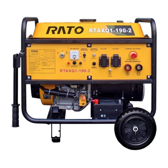
COMPONENT IDENTIFICATION II. COMPONENT IDENTIFICATION 1. Feature RTAXQ1-190/RTAXQ1-190D CURRENT EXCHANGE SWITCH AMMETER CURRENT ADJUSTER ENGINE SWITCH VOLTMETER DC 220V RECEPTACLE (P28J1A) AIR CLEANER WELDING FAST CONNECTOR (RECEPTACLE) RED RECOIL STARTER (WELDING OUTPUT + ) WELDING GRIP OUTPUT - (BLACK) FUEL TANK CAP... - Page 8 COMPONENT IDENTIFICATION RTAXQ1-190-2 CIRCUIT BREAKER VOLTMETER ENGINE SWITCH RECEPTACLE AUTO CHOKE LEVER THROTTLE CURRENT AIR CLEANER ADJUSTER FUEL VALVE WELDER TERMINAL RECOIL GROUND STARTER GRIP TERMINAL BATTERY FUEL TANK CAP FUEL METER MUFFLER CARBURETOR · 6 ·...
- Page 9 COMPONENT IDENTIFICATION 2. Model No. MODEL NO. FINISHED PRODUCT NO. SER. NO. · 7 ·...
-
Page 10: Control
CONTROL III. CONTROL 1 . Engine Switch Engine switch: press the button up to " START" position. the engine will start .After starting engine, immediatelly release engine switch and engine switch can automatically return to "ON" position; press the button down to "OFF"... - Page 11 CONTROL 3. Fuel Valve Fuel valve: fuel flows from the fuel tank to carburetor when the fuel valve is in "ON" position and in " OFF" position will cut off fuel flowing to carburetor. FUEL VALVE 4. Choke Lever Chock lever: in "CLOSE" position, carburetor provides an enriched fuel mixture;...
- Page 12 CONTROL 6. Ground Terminal This ground terminal is specially used to connect the welder to the ground. GROUND TERMINAL 7. Current Adjuster Adjust the current according to welding requirement. · 10 ·...
- Page 13 CONTROL 8. Auto Throttle The solenoid valve will operate and engine keep idele speed when the switch turn ON and electric welder set is no load.For engine operating, switch ON the load and solenoid valve disconnect. 9. Oil Alert System The oil alert system is especially designed to prevent welder from damaging caused by an insufficient amount of oil in the crankcase.
-
Page 14: Welder Operation
WELDER OPERATION IV. WELDER OPERATION 1. Welder Operation Environment: 1) Height above sea level: Do not exceed 1000 ml. 2) Operation environment temperature. welding:-10 ~+ 40 ℃ ; transportation and storage: -25 ~ +55 ℃ . 3) Air relative humidity: Don’t exceed 50% at 40 ℃ ; and don’t exceed 90% at 20 ℃... - Page 15 WELDER OPERATION GROUND TERMINAL 3. Auxiliary Power Supply 1.This series welder is with auxiliary DC output. The voltage is 220V, which can be used for the electrical tools below 3KW with carbon brush. 2.This series welder is with auxiliary AC output. The voltage is 230V, which can be used for the electrical tools below 3.5KW with carbon brush.
-
Page 16: Check Before Operation
CHECK BEFORE OPERATION V. CHECK BEFORE OPERATION 1. Engine Oil Before operation, please stop the welder and put on the flat surface to check the oil level. Engine oil is a major factor affecting engine performance and service life. Non-detergent and 2-stroke engine oils will damage the engine and are not recommended. - Page 17 CHECK BEFORE OPERATION 2. Fuel 1) Check the fuel level gauge, 2) Refill the tank if the fuel level is too low. Do not fill above the shoulder of the fuel strainer. 3) Reinstall and tighten the fuel tank cap after refueling. FULL EMPTY FUEL MAXIMUM UPPER LEVEL FUEL TANK CAP...
- Page 18 CHECK BEFORE OPERATION Never use stale or contaminated gasoline or oil/gasoline mixture. Avoid dirt or water entering into the fuel tank. 3. Battery Please use battery with voltage 12V. Don’t connect the battery positive and negative poles in reverse (Pay attention to leads mark), when connecting, first connect positive poles, then negative poles, when disassembling, first negative pole, then positive pole , if not, can seriously damage the welder and...
-
Page 19: Starting The Welder
STARTING THE WELDER VI. STARTING THE WELDER 1. Recoil Starter 1) Remove all the loads out of the output terminal. 2) Turn the fuel valve to “ON” position. 3) Turn the choke lever to “CLOSE” position. Don’t’ close the choke lever when starting the engine in warm state. 4) Turn the engine switch to “ON”... - Page 20 STARTING THE WELDER can damage the starting motor. If failing to start, release the switch and wait 10 seconds before operating it again. If the speed of the starting motor drops fast after a period of time, it means that the battery should be recharged. ·...
-
Page 21: Stopping The Welder
STOPPING THE WELDER VII. STOPPING THE WELDER 1. Turn the AC circuit breaker to “OFF” position. 2. Turn the engine switch to the “OFF” position. 3. Turn the fuel valve to the “OFF” position. If need to stop the engine in an emergency, turn the engine switch to “OFF”... -
Page 22: Maintenance
MAINTENANCE VIII. MAINTENANCE Good maintenance is essential for safe, economical, and trouble-free operation. It will also help reduce air pollution. Exhaust gas contains poisonous carbon monoxide. Shut off the engine before performing any maintenance. If the engine must be run, make sure the area is well ventilated. - Page 23 MAINTENANCE Improper maintenance or failure to modify a problem before operation can cause a malfunction in which you can be seriously hurt or killed. Always follow the inspection and maintenance recommendations and schedules in this owner’s manual. 1 . Engine Oil Change Drain the oil while the engine is warm to assure complete.
- Page 24 MAINTENANCE environment. We suggest you take it in a sealed container to your local service station or recycling center for reclamation. Do not throw it in the garbage or dump it on the ground and in the raceway. 2. Air Cleaner Service A dirty air cleaner will restrict air flow to the carburetor.
- Page 25 MAINTENANCE AIR CLEANER ELEMENT AIR CLEANER COVER CONNECTION BOLT FOAM ELEMENT 3) Reinstall the air cleaner element and the cover. 3. Fuel Sediment Cup Cleaning 1) Turn the fuel valve to “OFF” position. Remove the sediment cup, o-ring and strainer. 2) Clean the sediment cup, and o-ring, and strainer in nonflammable or high flash point solvent.
- Page 26 MAINTENANCE 4. Spark Plug Recommended spark plugs: F7RTC. 1) Remove the spark plug cap. 2) Use the plug wrench to remove the spark plug. PLUG WRENCH SPARK PLUG CAP 3) Inspect the spark plug visually if the insulator is broken, if broken, replace with new the spark plug.
-
Page 27: Storage
STORAGE IX. STORAGE In order to avoid inflammation or fires because of contacting with a hot engine or exhaust system, let the engine cool before storing the welder. If storing the welder for a long time, make sure the storage area is clean and dry. - Page 28 STORAGE 2. Screw the oil dipstick off and screw the drain bolt off the crankcase to drain the oil out completely. And then tighten the drain bolt and fill fresh oil to upper mark, finally reinstall the oil dipstick well. 3.
-
Page 29: Troubleshooting
TROUBLESHOOTING X. TROUBLESHOOTING 1 . Engine Is Unable To Start: Refill the fuel tank. Is there fuel in the tank? Is there enough oil in the Add the recommended engine? oil. Still NO Take the welder Replace the Is there a spark from the spark to an authorized spark plug. - Page 30 TROUBLESHOOTING 2. Without No Load Voltage Or Unable Generating Electricity (RTAXQ1-190/RTAXQ1-190D) Carbon brush is unable Replace to contact. Rotor wire is broken, stator Replace rotor/stator excitation wire is broken. Residual magnetism is Charge magnetism lacking The resistance of the control Replace magnetic panel magnetic disk is damaged.
- Page 31 TROUBLESHOOTING 3. Without Auxiliary Power Supply.(RTAXQ1-190/RTAXQ1-190D) MDS30 module is damaged Replace MDS30 module 30A fuse is broken Replace Plug-in parts is loosen Replace Replace Circuit Breaker is damaged. Take the welder to an authorized welder dealer. 4. Maximum Current Lack Or Without Maximum Current Output.
- Page 32 TROUBLESHOOTING 5.No no-load voltage or unable generating electricity (RTAXQ1-190-2) poor contact of motor carbon change carbon brush rotor, stator damaged change rator/stator Field coil damaged or poor change or connect well contact Porcelain disk resistor of c h a n g e p o r c e l a i n d i s k...
- Page 33 TROUBLESHOOTING 7.Low max. current or no max. current output(RTAXQ1-190-2) the module of control welding c h a n g e t h e m o d u l e f o r current broken controlling welding current MDS200A module broken...
-
Page 34: Wiring Diagram
WIRING DIAGRAM XI. WIRING DIAGRAM RTAXQ1-190 · 32 ·... - Page 35 WIRING DIAGRAM RTAXQ1-190D · 33 ·...
- Page 36 WIRING DIAGRAM RTAXQ1-190-2 · 34 ·...
-
Page 37: Specifications
SPECIFICATIONS XII. SPECIFICATIONS Items RTAXQ1-190 RTAXQ1-190D RTAXQ1-190-2 No load voltage (V) ≥60 Rated welding voltage(V) Welding current (A) Welder Frequency (Hz) Cyclic duration factor 100% 100% 100% Auxiliary power supply(V/kW) 220/3(DC) 220/3(DC) 230/3.5(AC) Current adjusting (A) 50-190 50-190 50-190 Welding rod(mm) -
Page 38: Wheel (Option)
WHEEL (OPTION) XIII. WHEEL (OPTION) 1. Install the two wheels on the wheel axle with gaskets and pins. 2. Install the wheel set on the bottom plate of the welder frame with bolts and nuts. · 36 ·... - Page 40 93004-X010220-0000...
Need help?
Do you have a question about the RTAXQ1-190 and is the answer not in the manual?
Questions and answers