Table of Contents
Advertisement
Quick Links
INSTRUCTION MANUAL
IMPORTANT: Read carefully. It is essential for the correct and safe use of the
equipment that erectors and operators should be fully conversant with the
information and instructions given in this manual.
1
INSTALLING THE PROJECTOR
• Unpacking
Open the box, remove the projector from the packing and place it on a flat hori-
zontal surface. Unpack the standard accessories supplied with the equipment.
Inspect the lamp change label (1) and replace with one of the optional language
versions if necessary.
Make certain that the label is never removed, as it displays important safety
information.
• Initial assembly operations
Position the bracket (2) the desired height and secure by tightening the knobs (3).
The bracket can also be fitted from the underside of the projector.
2
• Fitting the lamp
Refer to directions for replacement of the lamp given under heading 6 MAINTENANCE.
• Installing the projector
The projector can be mounted in any position without its operating characteristics
being affected.
IMPORTANT: fix the projector in the desired position utilizing the holes in the brack-
et (2). Secure preferably using two ø10 bolts with nuts and lock washers.
Make certain that the anchorage is stable before positioning the projector.
• Minimum distance from target objects
The projector must be positioned in such a way
that objects struck by the beam are separated
from the lens at least by the distance indicated on
the lamp change label next to the symbol illustrat-
ed alongside.
• Minimum distance of inflammable materials from any part of the equip-
ment: 0.10 m (4").
The appliance may be mounted on surfaces rated normally inflammable.
IMPORTANT: For better and more reliable operation of the projector, the ambient
temperature must not exceed 35° C (95° F). Protection factor IP 20: the appliance is
protected against penetration of solid bodies more than 12mm (0.5") in diameter (first
digit 2), but can be damaged by spray, jet, drip or rain water (second digit 0).
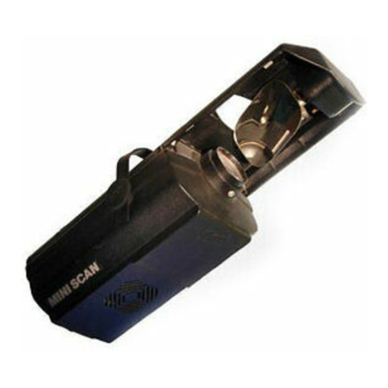
MINISCAN
1
3
2
(
)
3' 3"
HMD 300
1.0 m
HTI 300
(
1' 8"
)
HTI 150
0.5 m
2
POWER SUPPLY AND INTERFACE
• Connecting to the electrical power supply
The operations described in this heading must be carried out by a licensed elec-
trician.
The projector must be wired up to the electrical power supply using the special
socket connector provided. It is good policy to connect projectors to the power
supply by way of dedicated switches, so that each can be turned on and off indi-
vidually from a remote station.
4
L
Mains
N
The projector is designed to operate at the voltage and frequency indicated on the
electrical data plate (4) affixed to the rear end. Check that these two values corre-
spond to the mains voltage and frequency.
IMPORTANT: the projector must be connected to a power supply circuit having
a proper earth system (Class I appliance).
• Connecting the control signals
0-10V CONNECTION
- Projectors operating independently of one another
0 - 10V
- Projectors operating simultaneously and identically
0 - 10V
The connection between controller and projec-
tor must be made using a multicore cable with 8
wires of 0.25mm
2
section and a DIN 8 PIN 45°
plug/socket connector.
RS 232/423(PMX) - DMX 512 CONNECTION
DMX 512
RS 232/423
5
Projectors are wired up to the controller and one to the next using two-core screened
cable and Cannon 5 pin XLR type plug/socket connectors.
HMD 300
HTI 300
HTI 150
0 - 10V
0 - 10V
TILT
8
7
6
3
1
Is
COL
2
5
4
GOBO
PAN
7
Advertisement
Table of Contents

Related Manuals for Clay Paky MINISCAN HMD 300


Summary of Contents for Clay Paky MINISCAN HMD 300
- Page 1 HMD 300 MINISCAN HTI 300 HTI 150 INSTRUCTION MANUAL POWER SUPPLY AND INTERFACE IMPORTANT: Read carefully. It is essential for the correct and safe use of the • Connecting to the electrical power supply equipment that erectors and operators should be fully conversant with the The operations described in this heading must be carried out by a licensed elec- information and instructions given in this manual.
- Page 2 To connect a DMX line, a terminating plug (7) with a 100Ω resistor wired between pins • Adjusting the lens 2 and 3 must be fitted to the last projector connected in series; the plug is not required Move the lens (6) back and forward until the projected image is satisfactorily focused, when using a RS232/423(PMX) signal.
- Page 3 • PAN - channel 3 LENS UNITS GRAPHS SHOWING BEAM DATA AND ILLUMINATION VALUES Objective 1:2,5/165mm - Standard equipment Miniscan 300 (HMD) (lux) 1980 Miniscan 300 (HMD) (fc) 20,4 11,5 9 10 Miniscan 300 (HTI) (lux) 2610 Miniscan 300 (HTI) (fc) 60,4 26,9...
- Page 4 • Changing the lamp (MINISCAN 300) TROUBLESHOOTING Open the projector, loosen the two side nuts (11) of the lamp to be changed and remove it from the supports (12). Remove the new lamp from its packaging, loosen the two side nuts (11) and locate PROJECTOR DOES NOT LIGHT UP the lamp in the supports (12).
- Page 5 MINISCAN 150 The specifications published in this manual are not binding, and may be revised or updated at any time by Clay Paky without notice in the interests of improving product quality. The products referred to in this manual comply with EC Directives on: •...
Need help?
Do you have a question about the MINISCAN HMD 300 and is the answer not in the manual?
Questions and answers