Table of Contents
Advertisement
Advertisement
Table of Contents

Related Manuals for roco multiMAUS


Summary of Contents for roco multiMAUS
- Page 1 10810 multiMAUS Handbuch � Manual �� Manuel � Manuale �...
-
Page 2: Table Of Contents
ABLE OF ONTENT The evolution of the ROCO Lokmaus – the multiMAUS ..............An overview of the multiMAUS ....................... Section 1 • Basics – Get to know the multiMAUS Connecting the multiMAUS ......................�� The display screen ..........................The keys ............................ -
Page 3: The Evolution Of The Roco Lokmaus - The Multimaus
The multiMAUS brings together the functionality of the legendary Lokmaus with the comfort of a fully digital central control unit. Whether you use the multiMAUS as just a comfortable controller or wish to use it for comprehensive programming of your locomotive decoder and turnouts, the clear layout of the design and simple operation make the multiMAUS the leading digital model railroading controller. -
Page 4: Connecting The Multimaus
If you use a Lokmaus 2 / R3 as a master, you will be unable to use some of the functions performed by a multiMAUS set as a slave. We therefore recommend that you use a multiMAUS as the master. See also the chapter “M... -
Page 5: The Display Screen
ISPLAY CREEN All the functions of the multiMAUS can be checked on the large LCD with backlight. The symbols are as follows: Drive symbols Wrench Turnout symbol – Arrows shows the direction of – the multiMAUS is in the (locomotive / turnout key) travel of the selected locomotive “Settings”... - Page 6 – Switch the light on or off (in drive mode) Light / OK key – Confirm inputs (in turnout mode and in the menus) – Call up desired menu level or menu items – in combination with — In locomotive address mode: –...
-
Page 7: Operating The Multimaus
PERATING THE Despite its numerous options, operation of the multiMAUS is simple and intuitive. A concept which had already been successfully introduced for the Lokmaus models of the first and second generation. The fol- lowing shows you how to operate the multiMAUS based on practical examples. - Page 8 “1” key. Correct input errors by using the left “arrow key” to move back one or more spaces. Confirm by pressing “OK” The multiMAUS then switches to the loco- motive address. The “suggested value” is dis- played, in this case “3”.
- Page 9 6, page 42). The locomotive can now be controlled. 2.2. Locomotive address mode The multiMAUS also gives you the option of controlling your loco- motives using the decoder address only. The display screen shows the locomotive address with the letter “L” before it (in this case, locomotive address 36), the locomotive symbol and all the selected functions.
-
Page 10: Driving And Functions
Backwards Standstill Forwards �� If another multiMAUS or Lokmaus is used to control a locomotive, the locomotive symbol flashes. See also the chapter “T “ on page 54. HE MASTER SLAVE PRINCIPLE The locomotive functions, e.g. -
Page 11: The Emergency Stop Functions
The locomotive stop is released by turning the controller, the locomotive starts to move again. Turnout control You can use the multiMAUS to control up to 1,024 digital turnout drives with genuine turnout ad- dresses without having to use up a locomotive address (as is the case with the Lokmaus 2 / R3). To do so, you can switch to turnout mode and back at any time by pressing the “Locomotive / turnout”... - Page 12 Input Display message Comment After the “Locomotive / turnout” key has been pressed, the multiMAUS switches from drive mode (library or locomotive address mode) to turnout mode. The turnout last called up always appear. In this case, turnout “6”, position “straight-on”.
-
Page 13: Quick-Programming
This provides you with quick access to two sets of turnouts which, for instance, are next to each other on a stretch of track. Address scrolling Press the “shift” key and one of the “arrow keys” at the same time and the multiMAUS will scroll through all the turnout addresses. ��... -
Page 14: Short Circuit And Overload
Short circuit and overload If a short circuit or an overload occurs on the system, the multiMAUS indicates this using two flashing symbols on the display screen: a streak of lightning and the STOP symbol At the same time the voltage supply to the system is shut off. -
Page 15: The Menu Functions Of The Multimaus
Press the “MENU” key (alone or together with the shift key) to exit all levels immediately and return to locomotive and turnout mode. All of the menus of the multiMAUS can be found in the large overview on the next two pages. -
Page 16: Overview Of The Menu Structure
CV MODIFICATION PROGRAM �� EDIT LONG ADDRESS DELETE SEARCH Basic instructions for operating the menu functions and programming: – Move within the menu level (i.e. in this overview, from top to bottom) to access the individual menus by pressing one of the two arrow SEND keys. - Page 17 Settings “STOP” key. Library Always program on a programming track which is fully disconnected from the rest of Speedsteps the system (exception: you have switched Factory Reset the multiMAUS to POM mode (page 49)). Calibration STOP-MODE Software X-Bus Command Station...
-
Page 18: The "Loco" Menu
” M The multiMAUS uses the “LOCO” menu to manage all data which is required for the locomotive library and for identification of a locomotive. You can also use this menu to set the multiMAUS to library or address mode. - Page 19 1.4. “SEARCH“ This could be one of the most important functions of your multiMAUS. You can use this menu item to assign a locomotive address to the corresponding locomotive in the library. Simply enter a locomotive address using the “function keys” and the multiMAUS will find the cor- responding locomotive in the library.
-
Page 20: The "Programming" Menu
ROCO decoders already installed in locomotives are usually delivered with the suitable settings. You should therefore check before performing programming whether it is really necessary. The ROCO amplifiers 10761 and 10764 and booster 10762 and 10765 cannot read the CVs from a de- ��... -
Page 21: The "Settings" Menu
The most extensive multiMAUS menu contains all the data which is practical, useful or sometimes necessary for basic operation of the multiMAUS. We would also like to point out at this point that the multiMAUS is provided with all the necessary settings in the factory so that you have to use this main menu either rarely or not at all. - Page 22 ” M ETTINGS 3.2.4. The multiMAUS has „CHILD LOCK“ which can be set to multiple levels and can be activated after calling up the menu item using the „arrow keys“. To block an area, you will need to enter a code which is comprised of 4 numbers (no letters!).
- Page 23 ” M ETTINGS 3.5. “RESET“ The multiMAUS is a particularly user-friendly digital controller and can be reset to the factory settings, not just completely but also partially. 3.5.1. “CANCEL” can be regarded as the emergency exit from this menu item. ��...
-
Page 24: Compatibility Of The Multimaus - All Useable Devices
ROCO add-on devices. The ROCO Lokmaus Digital-is-Cool system – 1 10750 and central control unit 10751 – can be used with the multiMAUS without restriction to all its functions. All you need is the 10759 translation device which is connected directly (or via the 10758 distributor) to the “Slave”... -
Page 25: The Master-And-Slave Principle
If a multiMAUS is plugged into the master connection on the amplifier, it automatically becomes the mas- ter. This multiMAUS is then the higher order instance – the central control unit – in the digital system. In order to be able to use all functions without restrictions, you should only connect one multiMAUS to this connection on the amplifier. -
Page 26: The 10765 Booster
Switch off the system before installing a booster. Divide the system into supply sections. Disconnect the tracks electrically from each other in the respective places (on both sides!) wether using ROCO insulating rail connectors 42611 or 61192, insulated track or by sawing the rail profiles. Install a section of power track (e.g. -
Page 27: Terminal Loops In Digital Operation
All values which affect the behaviour of the locomotive decoder – and ultimately the behaviour of the locomotive – are stored in what are referred to as CVs. CV is the abbreviation for configuration variables. The multiMAUS is compatible with the NMRA / DCC standard and can therefore read and write these vari- ables. -
Page 28: Hints, Tips & Help
Modern decoders (from about 2000 onwards) can be controlled using at least 28 speed steps. They auto- matically set to the number of speed steps set in the locomotive controller (i.e. the multiMAUS) so that you do not need to make the setting in the decoder yourself. See the respective operating manual to determine whether your decoder is compatible with automatic speed step setting and which speed steps ��... -
Page 29: Programming Help For Lokmaus 2 / R3 - Multimaus
(see page � Change speed steps The ROCO electrics handbook, article number 82071, which is available as a CD-ROM from your local dealer, includes many tips and much information on the subject of model railway electrics and digital technology. The ROCOMOTION system controller also has numerous options which can also be used in conjunc- tion with the multiMAUS. -
Page 30: Error Messages
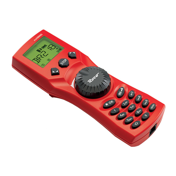
If this does not solve the problem, check the X-Bus address. ERR 14: The calibration values are invalid. The controller needs to be recalibrated. See page 52, 3.5.6. ERR 90 and above: Your multiMAUS is unfortunately in need of service by the ROCO service department. - Page 31 Fig. 1 LC-Display Stop-Taste LC display Stop Key Écran touche »Stop« LC display Tasto di arresto Pfeiltaste Pfeiltaste (links) (rechts) Arrow Key Arrow key (left) (right) touche »flèche« touche »flèche« (à gauche) (à droite) Tasto freccia Tasto freccia (sinistra) (destra) Fahrregler control knob Licht / OK-Taste...
- Page 32 Setting up the ROCO digital system (Europe version with 230 V) with the multiMAUS. Structure de la commande numérique ROCO (version européene à 230 V) avec la multiMAUS (=multiSOURIS). Struttura del sistema digitale ROCO (versione europea a 230 V) con il multiMAUS.
- Page 33 Fig. 3 Anschluss eines Boosters 10765 an den Verstärker 10764 und die Gleisanlage. Wiring diagram of the amplifier 10764, the booster 10765 and the tracks. Comment câbler l‘amplificateur complémentaire réf. 10765 avec l‘amplificateur principal réf. 10764 et la voie. Come collegare l‘amplificatore 10764, il booster 10765 e i binari. 62 62...
- Page 34 Fig. 4 Übergangsstrecke Digital — Gleichstrom mit dem Trennmodul 10768. Pass-over section with additional tracks from digital to DC-layout controlled by the Separator module 10768. Canton de transition de la section en commande numérique à celle en commande analogique avec le module 10768.
- Page 35 Fig. 5 ����� Eine digitale Kehrschleife mit dem Kehrschleifenmodul 10769. A digital turning loop controlled by the modul 10769. Branchement d‘une boucle de retournement en commande numérique contrôlée par le module réf. 10769. Una linea di raccordo digitale controllata per il modulo 10769. Hinweis / Note / À...
- Page 36 Kurzübersicht / Overview Fahren / Driving Lokauswahl Nothalt Licht STOP Light Loco selection Emerg. Stop Funktionen / Functions � … … F1 – F10 F11 – F20 Weichen / Turnouts … Menüebene / Menu level � MENU oder zurück =...
Need help?
Do you have a question about the multiMAUS and is the answer not in the manual?
Questions and answers