Table of Contents
Advertisement
Advertisement
Table of Contents

Subscribe to Our Youtube Channel
Related Manuals for DX Engineering NCC-1


Summary of Contents for DX Engineering NCC-1
- Page 1 Receive Antenna Phasing Controller DXE-NCC-1 DXE-NCC-1-INS Rev 7b © DX Engineering 2017 1200 Southeast Ave. - Tallmadge, OH 44278 USA Phone: (800) 777-0703 ∙ Tech Support and International: (330) 572-3200 Fax: (330) 572-3279 ∙ E-mail: DXEngineering@DXEngineering.com - 1 -...
-
Page 2: Table Of Contents
Operation Using the NCC-1 Technical Description Specifications Appendix A NCC-1 Connection Diagram for High Power Operation NCC-1 Connection Connections for Remotely Powered Receive Antennas 28 Optional Items NCC-1 Receive Filters Receive Filters Graphs Receive Filter Installation Technical Support - 2 -... -
Page 3: Introduction
Reversible Beverages, Receive Four-Square Arrays, K9AY Loops, and more. It will increase the directivity of any properly spaced combination of two similar antennas. The NCC-1 is primarily designed for 500 kHz to 15 MHz use, although the useful operating range extends from below 300 kHz to above 30 MHz. -
Page 4: Features
See Appendix A for details. The NCC-1 is not a Digital Signal Processor (DSP) unit and it is not a Noise Blanker. The NCC-1 is a receive signal RF phasing controller with exceptionally low noise, high dynamic range, level control and phasing range. -
Page 5: Receiving Antennas
Please carefully read this section and make adjustments or changes to your antennas before using the NCC-1. The NCC-1 will function with almost any combination of antennas but it works best when INPUT A and B antennas have reasonably similar directional patterns. Optimum antenna spacing will vary with the frequency band and what you are trying to accomplish. -
Page 6: Combining Antennas To Improve Signal-To-Noise Ratio
Combining Antennas to Improve Signal-to-Noise Ratio If your location is limited by noise coming from many directions, you can still use the NCC-1 to enhance signals. The following guidelines apply when enhancing signals: Both antennas must hear the desired signal with similar signal-to-noise ratios. -
Page 7: Use With Beverage Or Other Low Noise Antennas
Connect another Beverage or another low noise receiving array to INPUT B Connect the NCC-1 RECEIVER connector to the receiver's input line. If you are using a Reversible Beverage, run two feedlines back to the NCC-1 INPUT connections. Then use the NCC-1 to control the directivity and nulls. -
Page 8: Phased Verticals & Beverage Systems
Phased Verticals & Beverage Systems This unit is an adjustable phasing network that combines two antenna input ports. Antennas can be combined to change or improve directional patterns. Pattern changes can be used to improve signal- to-noise ratio even in the absence of strong noise. It is possible to combine almost any type of receiving antennas into a large array. - Page 9 Two parallel Beverage antennas spaced an eighth to quarter wave apart with an eighth to quarter wave stagger in the desired direction can be combined to improve front-to-back ratio or steer nulls to the direction of unwanted signals or noise. The best system is often found by planning, although it is often worth experimenting.
-
Page 10: Noise
Unlike conventional noise blankers, the NCC-1 is designed to reduce noise or interference before it gets to the receiver. The NCC-1 can be effective on all types of noise, including interference (QRM) from unwanted signals. The NCC-1 allows the user to continuously adjust both phase and amplitude when combining two antenna inputs. -
Page 11: Removing Noise
Removing Noise The NCC-1 generally works best when both antennas have similar patterns, polarization, and Signal-to-Noise ratios. For the most effective nulling of noise, the antennas on both the A and B inputs must hear the same unwanted noise and should have similar polarization. You may have to experiment to find the best antenna, but successful operation more commonly occurs with similar antennas. -
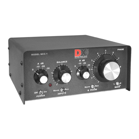
Page 12: Front Panel Controls And Switches
Front Panel Controls and Switches POWER: Turns power off and on. When powered-off, INPUT B is disconnected and INPUT A is connected directly to the receiver, removing antenna power. Two Attenuator switches reduce gain in ten dB steps. The steps are 0, -10, -20, and –30 dB. The left switch ... -
Page 13: Rear Panel Connections
The NCC-1 can supply T/R Controlled DC power to active antennas through the INPUT A and B coaxial lines. DC power can come from either the NCC-1 supply or through a separate rear panel power connector. The NCC-1 has an internal high-speed solid-state switch that will switch up to 30 Volts DC Positive voltage at 150 mA per input channel for powering receive antennas. -
Page 14: Internal Jumpers
With the unit unplugged and no power connected, remove 6 screws on each side of the cover and lift it off. To configure the jumpers, turn the NCC-1 so the components match the orientation of Figure 1. The Default jumper positions as shown: HD1 –... -
Page 15: Hd1 & Hd2 - Antenna Power Enable/Disable
When HD5 has two pin jumpers in both positions completely filling the header, operation is normal. A logic low activates the TX Mute. This means any voltage above 3 volts positive or an open circuit allows the NCC-1 to function normally. Power is available for use at antenna ports. -
Page 16: Installation
Connect a standard shielded audio style cable between the T/R Control Phono connector and an external transmit control source. o By default, the NCC-1 is set to mute when the T/R Control line is pulled LOW. This is normal station wiring. Many modern transceivers have a rear panel amplifier control jack typically labeled as "TX", "AMP", "Send”, “Control"... -
Page 17: Ncc-1 Dimensions
Connect the RX OUT jack to a receiver or the transceiver receive-only antenna port. Do not connect the RX OUT connector of the NCC-1 to a transceiver RF output! If desired, connect a fused external power source to the ANT PWR 2.1 mm center-positive jack if you are not using the NCC-1 supply to power antennas (HD4 Jumper Selectable). -
Page 18: Typical Connections To A Transceiver
Typical Connections to a Transceiver Figure 2 shows the normal default connection of the NCC-1 to a typical Transceiver with Receive Input. Antenna Inputs A and B may be connected to any receive antennas as discussed in the Introduction, and in the following pages. -
Page 19: Phase Nulling With A Transmit Antenna
'hear' the desired signal. Many of the low noise advantages of the NCC-1 will be hidden by strong ambient noise if a transmit antenna is used as a receive antenna for the NCC-1. - Page 20 Phase Nulling with a Transmit Antenna and a single Active Receive Antenna - 20 -...
- Page 21 Figure 4 - DXE-NCC-1 Receive Antenna Variable Phasing Controller with two Active Receive Antennas using high power to the transmit antenna - 21 -...
-
Page 22: One Active Receive Antenna, Rtr-1 And Transmit Antenna
Figure 5 - DXE-NCC-1 Receive Antenna Variable Phasing Controller with one Active Receive Antenna - 22 -... -
Page 23: Operation
For two antennas with approximately equal desired signal levels, or for two antennas with approximately equal undesired signals or noise levels. 1. Connect the NCC-1 to your station and a suitable power source. 2. Set the front panel controls as follows: A. -
Page 24: Using The Ncc-1
The most stable and reliable nulls occur when antennas are moderately close together (between 1/10 and 1/4-wavelength apart), oriented in the same direction, and sharing the same polarization. Using the NCC-1 The PHASE control changes the phase relationship between A and B INPUTs, effectively changing the direction of a peak or null. -
Page 25: Technical Description
There is virtually no channel balance error over the entire range of the phase control. The NCC-1 has a dynamic range up to 30 dB (1000 times) better than other popular noise canceling systems. It also has provisions for further improvements in exceptionally strong signal environments. -
Page 26: Specifications
Specifications Useable Frequency Range: 300 kHz to 30 MHz The NCC-1 is primarily designed for 500 kHz to 15 MHz use, although useful operating range extends from below 300 kHz to above 30 MHz. Third Order Output Intercept: +32 dBm each Input, +38 dBm both inputs combined ... - Page 27 - 27 -...
-
Page 28: Ncc-1 Connection Connections For Remotely Powered Receive Antennas
NCC-1 Connections for Remotely Powered Receive Antennas If your special receive antenna system requires any voltage, even those greater than +13.8 Vdc nominal, then the NCC-1 default internal jumper setting for HD4 is set to EXT. Refer to Figure A-2. This will allow... -
Page 29: Optional Items
DX Engineering’s Active Receive Antenna Systems offer excellent receiving performance from 100 kHz to 30 MHz using a whip antenna element 102 in. long. DX Engineering’s unique design makes it vastly superior to traditional active antennas in both strong signal handling and feedline decoupling. You get significantly better weak signal reception due to lower spurious signal interference and reduced noise. - Page 30 DXE-F6 - 75 ohm F-6 Style, Direct Bury Coaxial Cable: Full Spool or Custom Cable Assemblies DX Engineering recommends using a high quality 75 Ω “flooded” F6 type coaxial cable. Flooded style cables have the distinct advantage of automatically sealing small accidental cuts or lacerations of the jacket.
- Page 31 This special cable is used in applications where DC power is supplied from one device to another. The DXE-DCPC-24 is specifically used in a DX Engineering receiving antenna phasing system between the "PRE- AMP POWER OUT" port on the DXE-TVSU-1A Time Variable Sequence Unit, and the "ANT PWR" power input on the DXE-NCC-1 Receive Antenna Phasing Controller.
-
Page 32: Ncc-1 Receive Filters
By default, empty NCC-1 filter slots have jumpers to pass all signals. On the NCC-1 front panel, the BAND toggle switch "L" or "H" positions activate one of two filter sets, allowing over 360 degrees of phase rotation in two frequency ranges. The BAND switch “L”... -
Page 33: Receive Filters Graphs
Filter Graphs The following 18 charts show the response curves for the 18 optional filters that are available for the NCC-1. DXE-NCCFL-LP160M - Low Pass, 160 M and below - Cut off Frequency 2.30 MHz DXE-NCCFL-LP80M - Low Pass, 80 M and below - Cut off Frequency 4.00 MHz... - Page 34 DXE-NCCFL-LP40M - Low Pass, 40 M and below - Cut off Frequency 7.50 MHz DXE-NCCFL-LP20M - Low Pass, 20 M and below - Cut off Frequency 15.00 MHz - 34 -...
- Page 35 DXE-NCCFL-LP15M - Low Pass, 15 M and below - Cut off Frequency 22.00 MHz DXE-NCCFL-LP10M - Low Pass, 10 M and below - Cut off Frequency 30.00 MHz - 35 -...
- Page 36 DXE-NCCFL-HP160M - High Pass, 160 M and above - Cut off Frequency 1.65 MHz DXE-NCCFL-HP80M - High Pass, 80 M and above - Cut off Frequency 3.40 MHz - 36 -...
- Page 37 DXE-NCCFL-HP40M - High Pass, 40 M and above - Cut off Frequency 6.60 MHz DXE-NCCFL-HP20M - High Pass, 20 M and above - Cut off Frequency 13.70 MHz - 37 -...
- Page 38 DXE-NCCFL-HP15M - High Pass, 15 M and above - Cut off Frequency 20.20 MHz DXE-NCCFL-HP10M - High Pass, 10 M and above - Cut off Frequency 27.90 MHz - 38 -...
- Page 39 DXE-NCCFLBPF160M - Band Pass, 160 M only - Center Frequency 1.85 MHz DXE-NCCFL-BPF80M - Band Pass, 80 M only - Center Frequency 3.70 MHz - 39 -...
- Page 40 DXE-NCCFL-BPF40M - Band Pass, 40 M only - Center Frequency 7.15 MHz DXE-NCCFL-BPF20M - Band Pass, 20 M only - Center Frequency 14.15 MHz - 40 -...
- Page 41 DXE-NCCFL-BPF15M - Band Pass, 15 M only - Center Frequency 21.15 MHz DXE-NCCFL-BPF10M - Band Pass, 10 M only - Center Frequency 28.50 MHz - 41 -...
-
Page 42: Receive Filter Installation
360 degrees. You may want to experiment in swapping “H” and “L” sets to see how they perform in your unique set up. Using a Phillips Head Screwdriver, remove NCC-1 cover. Locate and remove four jumpers as shown. - Page 43 The installed filters sets will be activated when you switch the NCC-1 front panel switch “L BAND H”. When switched in the “L” the L set will be active, when the switch is in “H” position the H set will be active.
-
Page 44: Technical Support
All products manufactured by DX Engineering are warranted to be free from defects in material and workmanship for a period of one (1) year from date of shipment. DX Engineering’s sole obligation under these warranties shall be to issue credit, repair or replace any item or part thereof which is proved to be other than as warranted; no allowance shall be made for any labor charges of Buyer for replacement of parts, adjustment or repairs, or any other work, unless such charges are authorized in advance by DX Engineering.
Need help?
Do you have a question about the NCC-1 and is the answer not in the manual?
Questions and answers