Table of Contents
Advertisement
Quick Links
Advertisement
Table of Contents

Related Manuals for Beckhoff CB7268


Summary of Contents for Beckhoff CB7268
- Page 1 Original manual | EN CB7268 Computerboard 27.08.2020 | Version: 1.1...
-
Page 3: Table Of Contents
ACPI Settings Disabled .................... 35 8.3.7 Hardware Monitor ...................... 36 8.3.8 AMI Graphic Output Protocol Policy ................ 36 8.3.9 PCI Subsystem Settings .................... 37 8.3.10 USB Configuration ...................... 39 8.3.11 NVMe Configuration ...................... 40 8.3.12 Power Controller Options.................... 41 CB7268 Version: 1.1... - Page 4 10.1 Electrical data .......................... 77 10.2 Environmental conditions ........................ 77 10.3 Thermal specifications ........................ 78 11 Support and Service.......................... 79 12 Appendix I: Post Codes .......................... 80 13 Appendix II: Resources........................... 81 13.1 Interrupt CB7268 .......................... 81 13.2 PCI devices CB7268 ........................ 82 13.3 SMB devices CB7268........................ 83 Version: 1.1 CB7268...
-
Page 5: Documentation Issue Status
Documentation issue status Version Modifications 0.1 Preliminary version, mechanical part only 0.2 Preliminary version, BIOS entries added. 0.3 Preliminary version 1.0 Initial release, incl. change from BAseCon140 to BeaCon140 1.1 BIOS 0.14, updated and new cover page CB7268 Version: 1.1... -
Page 6: Notes On The Documentation
EP1590927, EP1789857, EP1456722, EP2137893, DE102015105702 with corresponding applications or registrations in various other countries. ® EtherCAT is registered trademark and patented technology, licensed by Beckhoff Automation GmbH, Germany Copyright © Beckhoff Automation GmbH & Co. KG, Germany. The reproduction, distribution and utilization of this document as well as the communication of its contents to others without express authorization are prohibited. -
Page 7: Safety Instructions
All the components are supplied in particular hardware and software configurations appropriate for the application. Modifications to hardware or software configurations other than those described in the documentation are not permitted, and nullify the liability of Beckhoff Automation GmbH & Co. KG. Personnel qualification This description is only intended for trained specialists in control, automation and drive technology who are familiar with the applicable national standards. - Page 8 Safety instructions Any other use is regarded as inappropriate. The specified limits for electrical and technical data must be adhered to. Version: 1.1 CB7268...
-
Page 9: Overview
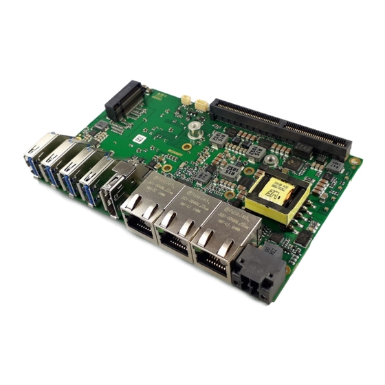
Standard interfaces include one DisplayPort connector in the front panel, 3 Gigabit LAN connectors and 4 USB3.1 GEN2 interfaces. The BeaCon140 connector allows flexible expansion of the CB7268's I/O functions. It provides 7 PCIe lanes, of which 4 can be multiplexed with SATA signals and 3 with USB 3.1 GEN2-signals. The configuration of the I/O functions is taken care of by the PIC on the expansion card. -
Page 10: List Of Features
Availability of the processors The list of features lists all the processors that can be ordered. Their actual availability depends on the manufacturer. List of features CB7268 120 x 75 Board CPU Intel® Celeron® 4305U (DC, 2M, 2.0 GHz), TDP 15 W Intel®... -
Page 11: Specifications And Documents
• www.intel.com • Intel® chip description • i210 datasheet • i219 data sheet • www.intel.com • American Megatrends® • Aptio™ Text Setup Environment (TSE) User Manual • www.ami.com • American Megatrends® • Aptio™ 5.x Status Codes • www.ami.com CB7268 Version: 1.1... -
Page 12: External Connections
External connections External connections External connector overview The figure shows the external interfaces of the CB7268. The following list shows the interfaces with reference to the respective manual page, where further information about the respective interface can be found. Fig. 2: CB7268, external interfaces Front panel The illustration corresponds to the installation situation in the PC housing. -
Page 13: Front Panel: Power Supply (X101)
External connections Front panel: Power supply (X101) Fig. 3: CB7268 Power X101 The connection for the power supply is implemented as a 2x2 pin housing connector (P20THR-1818504). The main power supply (24 V) for the module is on pin 3. This can also be implemented as UPS-OCT (One Cable Technology), i.e. -
Page 14: Front Panel: Lan 1 - 3 (X102, X103, X104)
The required speed is selected automatically. Auto-Cross and Auto- Negotiate are available as well as PXE and RPL functionality. The controller is Intel®'s i219 for LAN1 and i210 for LAN 2 and LAN3. Fig. 4: CB7268 LAN X102-104 Pin assignment of LAN connector: Pin Name... -
Page 15: Front Panel: Displayport (X105)
DPA1-4H) with one DisplayPort connection is available. The interface additionally provides HDMI/DVI signals that can be used with aid of an adapter. Please consult your distributor with regard to a suitable adapter. Fig. 5: CB7268 DP Out X105 Pin assignment of DisplayPort plug: Description Signal... -
Page 16: Front Panel: Usb 3.1 Gen2 (X106-X109)
USB support. This function should not be selected for settings in the setup and for booting Windows with a USB mouse and keyboard connected, because this would lead to considerable performance limitations. Fig. 6: CB7268 USB3.1 X106-109 Pin assignment USB3.1 Gen2 connector: Pin... -
Page 17: Internal Connections
Internal connections Internal connections Internal connector overview The figure shows the internal interfaces of the CB7268. The following list shows the internal connectors with reference to the respective manual page, where further information about the respective connector can be found. -
Page 18: Internal: Beacon140
Internal connections Internal: BeaCon140 In conjunction with the chipset, the BeaCon140 connector allows flexible extension of the CB7268's I/O functions. It provides up to 7 PCIe lanes, of which a maximum of 4 can be multiplexed with SATA3.0 (6G) and a maximum of 4 with PCIe lines, as well as a maximum of 3 PCIe lines with a maximum of 3 USB3.1- GEN2 lines (see table). - Page 19 Lane 7 active low Ground GND 68 GND Ground PCIe Lane 5 Transmit + PE5/USB3-4/ 70 RX-USBC1/ PCIe Lane 5 Receive + USBC1-TX USB3-4/PE5 PCIe Lane 5 Transmit - PE5/USB3-4/ 72 RX-USBC1/ PCIe Lane 5 Receive - USBC1-TX# USB3-4/PE5# CB7268 Version: 1.1...
- Page 20 DPL0/TMDSD2# 133 134 TMDSD1DPL1# DisplayPort Lane 1 - Ground GND 135 136 GND Ground DisplayPort Lane 2+ DPL2/TMDS0 137 138 TMDSD3/DPL3 DisplayPort Lane 3 + DisplayPort Lane 2 - DPL2/FMDS0# 139 140 TMDSD3/DPL3# DisplayPort Lane 3 - Version: 1.1 CB7268...
-
Page 21: Internal: Battery
Internal connections Internal: Battery The computer board has a two-pin battery connector. This allows an RTC battery to be connected directly to the computer board. Fig. 9: CB7268-G2-Bat Pin assignment: Battery connector Pin Signal Description 1 3.3 V_RTC 3.3 V for RTC of the CPU 2... - Page 22 Internal connections Internal: M.2 The CB7268 is equipped with an M.2 socket (KeyB) into which an M.2-2280 card or M.2-2242 card (Key B) can be inserted. Adapter cards with standard plug connectors are available as accessories. Please contact your distributor for this.
- Page 23 ANTCTL3 SIM DETECT (not led out) Power good RESET# SUSCLK System clock Configuration pin CFG1 3.3 V Standby S3.3 Volt Ground GND 3.3 V Standby S3.3 Volt Ground GND 3.3 V Standby S3.3 Volt Configuration pin CFG2 CB7268 Version: 1.1...
-
Page 24: Leds
LEDs LEDs Power control There is an RGB LED on the board with which status messages of the power controller are output by means of colors and flashing intervals. Fig. 12: CB7268 Power LED Color Interval Meaning None Steadily lit System in error state White... -
Page 25: Twincat
LEDs TwinCAT This RGB LED indicated the status of TwinCAT activity. Fig. 14: CB7268 TC LED Color Interval Meaning Green Steadily lit TwinCAT Run Mode Blue Steadily lit TwinCAT Config Mode Red Steadily lit TwinCAT Stop CB7268 Version: 1.1... -
Page 26: Ups-Oct
LEDs UPS-OCT An RGB LED on the board indicates the status of the OCT interface via colors and flashing intervals. Fig. 15: CB7268 OCT LED Color Interval Meaning None Steadily lit No UPS-OCT connected Blue Flashing Boot loader active Yellow Flashing Moderate signal quality... -
Page 27: Bios
It should also be noted that the settings shown in the setup menus below are not necessarily the recommended or default settings. Which settings must be selected depends on the application scenario in which the board is operated. CB7268 Version: 1.1... -
Page 28: Main
BIOS Main Aptio Setup Utility - Copyright (C) 2020 American Megatrends, Inc. Main Advanced Chipset Security Boot Save & Exit ┌─────────────────────────────────────────────────────────────────┬────────────────────────────────┐ │ │Set the Date. Use Tab to │ │ Board Information │switch between Date elements. │ │ Board CB7268 │Default Ranges: │ │ Revision 2 │Year: 2005─2099 │ │ Bios Version 0.14 │Months: 1─12 │ │ │Days: dependent on month │ │ Processor Information │ │ │ Name WhiskeyLake ULT │ │ │ Type Intel(R) Core(TM) │ │ │ i7─8665UE CPU @ 1.70GHz │ │ │ Speed 1700 MHz │ │ │ ID 0x806EC │ │ │ Stepping V0 ├────────────────────────────────┤ │ Number of Processors 4Core(s) / 4Thread(s) │→←: Select Screen │ │ Microcode Revision C6 │↑↓: Select Item │ │ GT Info GT2 (0x3EA0) │Enter: Select │ │ │+/─: Change Opt. │ │ IGFX VBIOS Version N/A │F1: General Help │ │ IGFX GOP Version 9.0.1105 │F2: Previous Values │ │ Memory RC Version 0.7.1.112 │F3: Optimized Defaults │ │ Total Memory 8192 MB │F4: Save & Reset │ │ Memory Frequency 2400 MHz │ESC: Exit │ │ │ │ │ PCH Information │ │ │ Name CNL PCH─LP │ │ │ Stepping DO │ │ │ │ │ │ ME FW Version 12.0.47.1524 │ │ │ │ │ │ System Date [Tue 02/10/2020] │ │ │ System Time [04:00:35] │ │ └─────────────────────────────────────────────────────────────────┴────────────────────────────────┘ Version 2.20.1275. Copyright (C) 2020 American Megatrends, Inc. BIOS entry Option... - Page 29 All Intel® processors have a certain base frequency and a specific TDP. Configurable TDP options mean that the computer manufacturer can change the base frequency and TDP of the CPU within the specific values published on the product specification page at https://Ark.Intel.com. CB7268 Version: 1.1...
-
Page 30: Advanced
Submenu see: TLS Auth configuration [} 46] Network Stack Configuration Submenu see: Network Stack Configuration [} 47] Submenu see: Network stack configuration enabled [} 48] Intel ® Rapid Storage Technology Submenu see: Intel® Rapid Storage Technology [} 49] Intel ® Ethernet connection(2) I219- LM - 00:01:05:4E:97:84 Version: 1.1 CB7268... -
Page 31: Rc Acpi Settings
│ MSI enabled [Enabled] │ │ │ ├────────────────────────────────┤ │ │→←: Select Screen │ │ │↑↓: Select Item │ │ │Enter: Select │ │ │+/─: Change Opt. │ │ │F1: General Help │ │ │F2: Previous Values │ │ │F3: Optimized Defaults │ │ │F4: Save & Reset │ │ │ESC: Exit │ │ │ │ └─────────────────────────────────────────────────────────────────┴────────────────────────────────┘ Version 2.20.1275. Copyright (C) 2020 American Megatrends, Inc. BIOS entry Options RC ACPI settings PTID support Enabled / Disabled PECI access method Direct I/O / ACPI MSI enabled Enabled / Disabled CB7268 Version: 1.1... -
Page 32: Cpu Configuration
Enabled / Disabled PECI Enabled / Disabled Active Processor Cores All / 1 / 2 / 3 AES Enabled / Disabled Intel Trusted Execution Technology None Alias check request None DPR memory size (MB) None Reset AUX content None Version: 1.1 CB7268... -
Page 33: Trusted Computing Disable
Trusted Computing Disable Aptio Setup Utility ─ Copyright (C) 2020 American Megatrends, Inc. Advanced ┌─────────────────────────────────────────────────────────────────┬────────────────────────────────┐ │ Configuration │Enables or Disables BIOS │ │ Security Device Support [Disable] │support for security device. │ │ NO Security Device Found │O.S. will not show Security │ │ │Device. TCG EFI protocol and │ │ │INT1A interface will not be │ │ │available. │ │ ├────────────────────────────────┤ │ │→←: Select Screen │ │ │↑↓: Select Item │ │ │Enter: Select │ │ │+/─: Change Opt. │ │ │F1: General Help │ │ │F2: Previous Values │ │ │F3: Optimized Defaults │ │ │F4: Save & Reset │ │ │ESC: Exit │ │ │ │ └─────────────────────────────────────────────────────────────────┴────────────────────────────────┘ Version 2.20.1275. Copyright (C) 2020 American Megatrends, Inc. BIOS entry Options Configuration Security device support Disable / Enable No security device found CB7268 Version: 1.1... -
Page 34: Trusted Computing Enable
Disable block Sid Disabled / Enabled No security device found NOTE Activating the Enable settings Use "Quit without saving" followed by "Yes" to perform a reset and activate the settings. Please note that not all CPUs support this function. Version: 1.1 CB7268... -
Page 35: Acpi Settings Enabled
│ Lock Legacy Resources [Disabled] │ │ │ ├────────────────────────────────┤ │ │→←><: Select Screen │ │ │↑↓: Select Item │ │ │Enter: Select │ │ │+/─: Change Opt. │ │ │F1: General Help │ │ │F2: Previous Values │ │ │F3: Optimized Defaults │ │ │F4: Save & Reset │ │ │ESC: Exit │ │ │ │ └─────────────────────────────────────────────────────────────────┴────────────────────────────────┘ Version 2.20.1275. Copyright (C) 2020 American Megatrends, Inc. BIOS entry Options ACPI Settings Enable ACPI Auto Configuration Disabled / Enabled Enable hibernation Enabled / Disabled Lock legacy resources Disabled / Enabled CB7268 Version: 1.1... -
Page 36: Hardware Monitor
8.3.8 AMI Graphic Output Protocol Policy Aptio Setup Utility - Copyright (C) 2020 American Megatrends, Inc. Advanced ┌─────────────────────────────────────────────────────────────────┬────────────────────────────────┐ │ Intel(R) Graphics Controller │Output Interface │ │ Intel(R) GOP Driver [9.0.1105] │ │ │ Output Select [HDMI1] │ │ │ ├────────────────────────────────┤ │ │→←: Select Screen │ │ │↑↓: Select Item │ │ │Enter: Select │ │ │+/─: Change Opt. │ │ │F1: General Help │ │ │F2: Previous Values │ │ │F3: Optimized Defaults │ │ │F4: Save & Reset │ │ │ESC: Exit │ └─────────────────────────────────────────────────────────────────┴────────────────────────────────┘ Version 2.20.1275. Copyright (C) 2020 American Megatrends, Inc. BIOS entry Options Intel® Graphics Controller Intel® GOP Driver [9.0.1105] Output select DVI1 Version: 1.1 CB7268... -
Page 37: Pci Subsystem Settings
32 / 64 / 96 / 128 / 160 /192 / 224 / 248 / PCI bus clock VGA palette snoop Disabled / Enabled PERR# generation Disabled / Enabled SERR# generation Disabled / Enabled Above 4G Decoding Disabled / Enabled PCI Hot-Plug Settings Submenu see: PCI Hot-Plug Settings [} 38] CB7268 Version: 1.1... - Page 38 Disabled / 1 M / 2 M / 4 M / 8 M / 16 M / 32 M / 64 M / 128 M PFMMIO 32 bit resources padding Disabled / 1 M / 2 M / 4 M / 8 M / 16 M / 32 M / 64 M / 128 M Version: 1.1 CB7268...
-
Page 39: Usb Configuration
USB Mass Storage Driver Support Enabled / Disabled USB hardware delays and time-outs: USB transfer time-out 1 / 5 / 10 / 20 sec Device reset time-out 10 / 20 / 30 / 40 sec Device power-up delay Auto / Manual CB7268 Version: 1.1... -
Page 40: Nvme Configuration
BIOS 8.3.11 NVMe Configuration Aptio Setup Utility - Copyright (C) 2020 American Megatrends, Inc. Advanced ┌─────────────────────────────────────────────────────────────────┬────────────────────────────────┐ │ NVMe controller and Drive information │ │ │ │ │ │ No NVME Device Found │ │ │ ├────────────────────────────────┤ │ │→←: Select Screen │ │ │↑↓: Select Item │ │ │Enter: Select │ │ │+/─: Change Opt. │ │ │F1: General Help │ │ │F2: Previous Values │ │ │F3: Optimized Defaults │ │ │F4: Save & Reset │ │ │ESC: Exit │ └─────────────────────────────────────────────────────────────────┴────────────────────────────────┘ Version 2.20.1275. Copyright (C) 2020 American Megatrends, Inc. BIOS entry Options NVMe controller and drive information No NVME device found None Version: 1.1 CB7268... -
Page 41: Power Controller Options
None No OCT receiver (or OCT_UPS) found None No OCT UPS detected None USB disabled or USB cable not connected None UPS ACPI device Disabled / Prefer OCT / Prefer USB / Use OCT / Use USB CB7268 Version: 1.1... -
Page 42: Basecon* Configuration
┌─────────────────────────────────────────────────────────────────┬────────────────────────────────┐ │ BAseCon* Configuration │ │ │ │ │ │ BAseCon1 serial number xxxxxxxxxxxxxxx │ │ │ revision 5 │ │ │ Block 6 disabled Blockresource missing ├────────────────────────────────┤ │ │→←: Select Screen │ │ │↑↓: Select Item │ │ │Enter: Select │ │ │+/─: Change Opt. │ │ │F1: General Help │ │ │F2: Previous Values │ │ │F3: Optimized Defaults │ │ │F4: Save & Reset │ │ │ESC: Exit │ │ │ │ └─────────────────────────────────────────────────────────────────┴────────────────────────────────┘ Version 2.20.1275. Copyright (C) 2020 American Megatrends, Inc. BIOS entry Options BAseCon* Configuration BAseCon 1 serial number None revision None Block 6 disabled None *Old name for BeaCon140. Version: 1.1 CB7268... -
Page 43: Sata And Rst Configuration
│ SATA Test Mode [Disabled] │ │ │ RAID Device ID [Client] │ │ │> Software Feature Mask Configuration │ │ │ Aggressive LPM Support [Disabled] │ │ │ │ │ │ Serial ATA Port 0 Empty │ │ │ Software Preserve Unknown │ │ │ Port 0 [Enabled] │ │ │ Hot Plug [Disabled] │ │ │ Configured as eSATA Hot Plug supported ├────────────────────────────────┤ │ External [Disabled] │→←: Select Screen │ │ Spin Up Device [Disabled] │↑↓: Select Item │ │ SATA Device Type [Hard Disk Drive] │Enter: Select │ │ SATA Port 0 DevSlp [Disabled] │+/─: Change Opt. │ │ DITO Configuration [Disabled] │F1: General Help │ │ Serial ATA Port 1 Empty │F2: Previous Values │ │ Software Preserve Unknown │F3: Optimized Defaults │ │ Port 1 [Enabled] │F4: Save & Reset │ │ Hot Plug [Disabled] │ESC: Exit │ │ Configured as eSATA Hot Plug supported │ │ │ External [Disabled] │ │ │ Spin Up Device [Disabled] │ │ │ SATA Device Type [Hard Disk Drive] │ │ │ SATA Port 1 DevSlp [Disabled] │ │ │ DITO Configuration [Disabled] │ │ │ Serial ATA Port 2 Empty │ │ │ Software Preserve Unknown │ │ │ Port 2 [Enabled] │ │ │ Hot Plug [Disabled] │ │ │ Configured as eSATA Hot Plug supported │ │ │ External [Disabled] │ │ │ Spin Up Device [Disabled] │ │ │ SATA Device Type [Hard Disk Drive] │ │ │ SATA Port 2 DevSlp [Disabled] │ │ │ DITO Configuration [Disabled] │ │ └─────────────────────────────────────────────────────────────────┴────────────────────────────────┘ Version 2.20.1275. Copyright (C) 2020 American Megatrends, Inc. CB7268 Version: 1.1... - Page 44 HDD / SSD SATA port 0 DevSlp Disabled / Enabled DITO configuration Disabled / Enabled NOTE Serial ATA ports 0 - 2 The identical BIOS entries for ports 0 – 2 are listed as examples for port 0. Version: 1.1 CB7268...
- Page 45 Smart Response Technology Enabled / Disabled OROM UI normal delay 2 / 4 / 6 / 8 secs RST Force Form Disabled / Enabled System acceleration with Intel® Enabled / Disabled Optane™ memory CPU attached storage Enabled / Disabled CB7268 Version: 1.1...
-
Page 46: Tls Auth Configuration
Client cert configuration None 8.3.15.1 Server CA configuration Aptio Setup Utility - Copyright (C) 2020 American Megatrends, Inc. Advanced ┌─────────────────────────────────────────────────────────────────┬────────────────────────────────┐ │ │Press <Enter> to enroll cert. │ │> Enroll Cert │ │ │> Delete Cert │ │ │ ├────────────────────────────────┤ │ │→←: Select Screen │ │ │↑↓: Select Item │ │ │Enter: Select │ │ │+/─: Change Opt. │ │ │F1: General Help │ │ │F2: Previous Values │ │ │F3: Optimized Defaults │ │ │F4: Save & Reset │ │ │ESC: Exit │ │ │ │ └─────────────────────────────────────────────────────────────────┴────────────────────────────────┘ Version 2.20.1275. Copyright (C) 2020 American Megatrends, Inc. BIOS entry Options Enroll cert Submenu see: Enroll cert Delete cert None Version: 1.1 CB7268... -
Page 47: Network Stack Configuration
BIOS entry Options Network Stack Disabled / Enabled NOTE Network stack enabled If network stack is enabled, additional menu items for displaying and setting the LAN controllers are shown here. To do this, carry out a reset. CB7268 Version: 1.1... -
Page 48: Network Stack Configuration Enabled
Ipv6 HTTP support Disabled / Enabled IPSEC certificate Enabled / Disabled PXE boot wait time None Media detect count None NOTE PXE boot available PXE boot is available if you set network stack and Ipv4 PXE support to "Enable". Version: 1.1 CB7268... -
Page 49: Intel Rapid Storage Technology
PORT CONFIGURATION MENU NIC Configuration See submenu: NIC Configuration [} 50] Flashing LEDs None PORT CONFIGURATION INFORMATION UEFI driver None PBA adapter None Chip type None PCI device ID None PCI address None Link status None MAC Address None CB7268 Version: 1.1... - Page 50 │ │F1: General Help │ │ │F2: Previous Values │ │ │F3: Optimized Defaults │ │ │F4: Save & Reset │ │ │ESC: Exit │ │ │ │ └─────────────────────────────────────────────────────────────────┴────────────────────────────────┘ Version 2.20.1275. Copyright (C) 2020 American Megatrends, Inc. Bios entry Options Link speed Auto Negotiated / 10 Mbps Half / 10 Mbps Full / 100 Mbps Half / 100 Mbps Full Wake On LAN Enabled / Disabled Version: 1.1 CB7268...
-
Page 51: Driver Health
┌─────────────────────────────────────────────────────────────────┬────────────────────────────────┐ │> System Agent (SA) Configuration │System Agent (SA) Parameters │ │> PCHIO Configuration │ │ │ ├────────────────────────────────┤ │ │→←: Select Screen │ │ │↑↓: Select Item │ │ │Enter: Select │ │ │+/─: Change Opt. │ │ │F1: General Help │ │ │F2: Previous Values │ │ │F3: Optimized Defaults │ │ │F4: Save & Reset │ │ │ESC: Exit │ │ │ │ └─────────────────────────────────────────────────────────────────┴────────────────────────────────┘ Version 2.20.1275. Copyright (C) 2020 American Megatrends, Inc. BIOS entry Options System Agent (SA) Configuration Submenu see: System Agent SA Configuration [} 52] PCH-IO Configuration Submenu see: PCH-IO Configuration [} 54] CB7268 Version: 1.1... -
Page 52: System Agent Sa Configuration
Thermal device (B0:D4:F0) Enabled / Disabled GNA device (B0:D8:F0) Enabled / Disabled CRID support Disabled / Enabled Above 4GB MMIO BIOS assignment Disabled / Enabled X2APIC Opt Out Disabled / Enabled IPU device (B0:D5:F0) Disabled / Enabled Version: 1.1 CB7268... -
Page 53: Graphics Configuration
Options Graphics Configuration Graphics turbo IMON current None Skip Scanning of External Gfx Card Disabled / Enabled Primary Display Auto / IGFX / PCI / SG Select PCIE Card Auto / Elk Creek 4 / PEG Eval External Gfx Card Primary Display None Configuration Internal Graphics Auto / Disabled / Enabled GTT Size 2 / 4 / 8 MB Aperture Size 128 / 256 / 512 / 1024 / 2048 MB PSMI SUPPORT Disabled / Enabled DVMT Pre-Allocated 0M / 32M…60M DVMT Total Gfx Mem 128M / 256M / MAX Intel Graphics Pei Display Peim Disabled / Enabled VDD Enable Enabled / Disabled PM support Disabled / Enabled PAVP Enable Enabled / Disabled Cdynmax Clamping Enable Enabled / Disabled Cd Clock Frequency 337.5 / 450 / 540 / 675 Mhz CB7268 Version: 1.1... -
Page 54: Pch-Io Configuration
Enabled / Disabled M.2 slot 0 None CLKRUN# logic Enabled / Disabled State after G3 S0 state / S5 state Compatible revision ID None Legacy IO low latency Enabled / Disabled Enable TCO timer Enabled / Disabled Version: 1.1 CB7268... - Page 55 Aptio Setup Utility - Copyright (C) 2020 American Megatrends, Inc. Chipset ┌─────────────────────────────────────────────────────────────────┬────────────────────────────────┐ │ PCI Express Configuration │PCI Express Clock Gating │ │ │Enable/Disable for each root │ │ PCI Express Clock Gating [Disabled] │port. │ │ PCIE Port assigned to LAN 5 │ │ │ Peer Memory Write Enable [Disabled] │ │ │ Compliance Test Mode [Disabled] │ │ │ PCIe─USB Glitch W/A [Disabled] │ │ │ │ │ │ PCIe RP 1 (disabled on BAseCon) │ │ │ PCIe RP 2 (disabled on BAseCon) │ │ │ PCI Express Root Port 3 Lane configured as │ │ │ USB/SATA │ │ │ PCI Express Root Port 4 Lane configured as │ │ │ USB/SATA │ │ │ PCI Express Root Port 5 Lane configured as │ │ │ USB/SATA │ │ │ PCI Express Root Port 6 Lane configured as │ │ │ USB/SATA ├────────────────────────────────┤ │ │→←: Select Screen │ │ │↑↓: Select Item │ │ │Enter: Select │ │ PCIE Port 7 is assigned to LAN1 │+/─: Change Opt. │ │ PCIE Port 8 is assigned to LAN2 │F1: General Help │ │> PCIe Root Port 9 (to M.2─Slot0) │F2: Previous Values │ │ PCIe Root Port 10 (to M.2─Slot0) │F3: Optimized Defaults │ │ PCIe Root Port 11 (to BAseCon) │F4: Save & Reset │ │ │ESC: Exit │ │ PCIe Port 12 is assigned to LAN3 │ │ │ PCIe RP 13 (disabled on BAseCon) │ │ │ PCIe RP 14 (disabled on BAseCon) │ │ │ PCIe RP 15 (disabled on BAseCon) │ │ │ PCIe RP 16 (disabled on BAseCon) │ │ └─────────────────────────────────────────────────────────────────┴────────────────────────────────┘ Version 2.20.1275. Copyright (C) 2020 American Megatrends, Inc. CB7268 Version: 1.1...
- Page 56 PCIe RP 13 (disabled on BAseCon) Disabled / Enabled PCIe RP14 (disabled on BAseCon) Disabled / Enabled PCIe RP 15 (disabled on BAseCon) Disabled / Enabled PCIe RP 16 (disabled on BAseCon) Disabled / Enabled *Old name for BeaCon140. Version: 1.1 CB7268...
- Page 57 BIOS entry Options PCI express root port 9 Disabled / Enabled NOTE PCI Express Configuration The BIOS entries are shown here for port 9 as an example. For activation set the PCI Express root ports to “Enabled”. CB7268 Version: 1.1...
- Page 58 │ Detect Non─Comliance Device [Disabled] │Detect Non─Compliance PCI │ │ Prefetchable Memory 10 │Express Device. If enable, it │ │ Reserved Memory Alignment 1 │will take more time at POST │ │ Prefetchable Memory Alignment 1 │time. │ │ │────────────────────────────────│ │ │→←: Select Screen │ │ │↑↓: Select Item │ │ │Enter: Select │ │ │+/─: Change Opt. │ │ │F1: General Help │ │ │F2: Previous Values │ │ │F3: Optimized Defaults │ │ │F4: Save & Reset │ │ │ESC: Exit │ │ │ │ └─────────────────────────────────────────────────────────────────┴────────────────────────────────┘ Version 2.20.1275. Copyright (C) 2020 American Megatrends, Inc. BIOS entry Options Detect non-compliance device Disabled / Enabled Prefetchable Memory None Reserved Memory Alignment None Prefetchable Memory Alignment None Version: 1.1 CB7268...
- Page 59 HD Audio Configuration Aptio Setup Utility - Copyright (C) 2020 American Megatrends, Inc. Chipset ┌─────────────────────────────────────────────────────────────────┬────────────────────────────────┐ │ HD Audio Subsystem Configuration Settings │Control Detection of the │ │ │HD─Audio device. │ │ HD Audio [Enabled] │Disabled = HDA will be │ │ │unconditionally disabled │ │ │Enabled = HDA will be │ │ │unconditionally enabled. │ │ │ │ │ ├────────────────────────────────┤ │ │→←: Select Screen │ │ │↑↓: Select Item │ │ │Enter: Select │ │ │+/─: Change Opt. │ │ │F1: General Help │ │ │F2: Previous Values │ │ │F3: Optimized Defaults │ │ │F4: Save & Reset │ │ │ESC: Exit │ │ │ │ └─────────────────────────────────────────────────────────────────┴────────────────────────────────┘ Version 2.20.1275. Copyright (C) 2020 American Megatrends, Inc. BIOS entry Options HD audio subsystem configuration settings HD audio Enabled / Disabled CB7268 Version: 1.1...
-
Page 60: Security
│ │ │ └─────────────────────────────────────────────────────────────────┴────────────────────────────────┘ Version 2.20.1275. Copyright (C) 2020 American Megatrends, Inc. BIOS entry Options Password Description Minimum Length None Maximum Length None Administrator Password Here you can set an administrator password. User mode available Enabled / Disabled Secure Boot menu Submenu see: Secure Boot [} 61] Version: 1.1 CB7268... -
Page 61: Secure Boot
Disabled / Enabled Not Active Secure Boot Mode Custom / Standard Restore factory keys Submenu see: Restore factory keys [} 62] Reset To Setup Mode Submenu see: Reset To Setup Mode [} 63] Key Management Submenu see: Key Management [} 64] CB7268 Version: 1.1... - Page 62 │ └───────────────────────────────────────┘ : Select │ │ Change Opt. │ │ │F1: General Help │ │ │F2: Previous Values │ │ │F3: Optimized Defaults │ │ │F4: Save & Reset │ │ │ESC: Exit │ │ │ │ └─────────────────────────────────────────────────────────────────┴────────────────────────────────┘ Version 2.20.1275. Copyright (C) 2020 American Megatrends, Inc. BIOS entry Options System Mode None Secure Boot Disabled / Enabled Not Active Secure Boot Mode Custom / Standard Restore factory keys Install factory defaults (see box) Version: 1.1 CB7268...
- Page 63 │ eneral Help │ │ │F2: Previous Values │ │ │F3: Optimized Defaults │ │ │F4: Save & Reset │ │ │ESC: Exit │ │ │ │ └─────────────────────────────────────────────────────────────────┴────────────────────────────────┘ Version 2.20.1275. Copyright (C) 2020 American Megatrends, Inc. BIOS entry Options System Mode none Secure Boot Disabled / Enabled Not Active Secure Boot Mode Custom / Standard Reset To Setup Mode Reset To Setup Mode (see box) CB7268 Version: 1.1...
- Page 64 Submenu see: Restore DB faults [} 67] Secure Boot variables Press enter key PlatformKey(PK) Press enter key Key Exchange Keys Press enter key Authorized Signatures Press enter key Forbidden Signatures Press enter key Authorized TimeStamps Press enter key OsRecovery Signatures Press enter key Version: 1.1 CB7268...
- Page 65 │ Vendor Keys Modified │Delete all Secure Boot key │ │ │databases from NVRAM │ │ Factory Key Provision [Disabled] │ │ │> Restore Factory Keys │ │ │> Reset To Setup Mode │ │ │> Export Secure Boot variables │ │ │> Enroll Efi Image │ │ │ │ │ │ Device Guard Ready ┌───────── Reset To Setup Mode ─────────┐ │ │> Remove 'UEFI CA' from DB │ │ │ │> Restore DB defaults │ Deleting all variables will reset the │ │ │ │ System to Setup Mode │ │ │ Secure Boot variable │ Siz│ Do you want to proceed? │ ───────────────────────────│ │> Platform Key(PK) │ 86│ │ elect Screen │ │> Key Exchange Keys │ 156│───────────────────────────────────────│ elect Item │ │> Authorized Signatures│ 314│ Yes No │ : Select │ │> Forbidden Signatures│ 372└───────────────────────────────────────┘ Change Opt. │ │> Authorized TimeStamps│ 0│ eneral Help │ │> OsRecovery Signatures│ 0│ 0│ No Keys │F2: Previous Values │ │ │F3: Optimized Defaults │ │ │F4: Save & Reset │ │ │ESC: Exit │ │ │ │ └─────────────────────────────────────────────────────────────────┴────────────────────────────────┘ Version 2.20.1275. Copyright (C) 2020 American Megatrends, Inc. BIOS entry Options Vendor Keys None Restore To Setup Mode see box CB7268 Version: 1.1...
- Page 66 ┌─────────────────────────────────────────────────────────────────┬────────────────────────────────┐ │ Vendor Keys Modified │Copy NVRAM content of Secure │ │ │Boot variables to files in a │ │ Factory Key Provision [Disabled] │root folder on a file system │ │> Restore Factory Keys │device │ │> Reset To Setup Mode │ │ │> Export Secure Boot variables │ │ │> Enroll Efi Image │ │ │ │ │ │ Device Guard Ready │ │ │> Remove 'UEFI CA' from DB ┌───────── File System ──────────┐ │ │> Restore DB defaults │ │ │ │ │ No Valid File System Available │ │ │ Secure Boot variable │ Size│ K│ │ ──────────────────────────────│ │> Platform Key(PK) │ 862│ │────────────────────────────────│ : Select Screen │ │> Key Exchange Keys │ 1560│ │ Ok │ : Select Item │ │> Authorized Signatures│ 3143│ └────────────────────────────────┘ ter: Select │ │> Forbidden Signatures│ 3724│ 7 ─: Change Opt. │ │> Authorized TimeStamps│ 0│ 0│ No Keys │F1: General Help │ │> OsRecovery Signatures│ 0│ 0│ No Keys │F2: Previous Values │ │ │F3: Optimized Defaults │ │ │F4: Save & Reset │ │ │ESC: Exit │ │ │ │ └─────────────────────────────────────────────────────────────────┴────────────────────────────────┘ Version 2.20.1275. Copyright (C) 2020 American Megatrends, Inc. BIOS entry Options Vendor Keys None Enroll Efi Image see box Version: 1.1 CB7268...
- Page 67 ┌─────────────────────────────────────────────────────────────────┬────────────────────────────────┐ │ Vendor Keys Modified │Restore DB variable to factory │ │ │defaults │ │ Factory Key Provision [Disabled] │ │ │> Restore Factory Keys │ │ │> Reset To Setup Mode │ │ │> Export Secure Boot variables │ │ │> Enroll Efi Image │ │ │ │ │ │ Device Guard Ready │ │ │> Remove 'UEFI CA' from DB ┌───────── Restore DB defaults ─────────┐ │ │> Restore DB defaults │ │ │ │ │ Press 'Yes' to proceed 'No' to cancel │ │ │ Secure Boot variable │ Siz│ │ ───────────────────────────│ │> Platform Key(PK) │ 86│───────────────────────────────────────│ elect Screen │ │> Key Exchange Keys │ 156│ Yes No │ elect Item │ │> Authorized Signatures│ 314└───────────────────────────────────────┘ : Select │ │> Forbidden Signatures│ 3724│ Change Opt. │ │> Authorized TimeStamps│ 0│ 0│ No Keys │F1: General Help │ │> OsRecovery Signatures│ 0│ 0│ No Keys │F2: Previous Values │ │ │F3: Optimized Defaults │ │ │F4: Save & Reset │ │ │ESC: Exit │ │ │ │ └─────────────────────────────────────────────────────────────────┴────────────────────────────────┘ Version 2.20.1275. Copyright (C) 2020 American Megatrends, Inc. BIOS entry Options Vendor Keys None Restore DB faults see box CB7268 Version: 1.1...
- Page 68 ┌─────────────────────────────────────────────────────────────────┬────────────────────────────────┐ │ Vendor Keys Modified │Enroll Factory Defaults or │ │ │load certificates from a file: │ │ Factory Key Provision [Disabled] │ 1.Public Key Certificate: │ │> Restore Factory Keys │ a)EFI_SIGNATURE_LIST │ │> Reset To Setup Mode │ b)EFI_CERT_X509 (DER) │ │> Export Secure Boot variables │ c)EFI_CERT_RSA2048 (bin) │ │> Enroll Efi Image │ d)EFI_CERT_SHAXXX │ │ ┌──────────────────────────────┐│ 2.Authenticated UEFI Variable │ │ Device Guard Ready │ Key Exchange Keys ││ 3.EFI PE/COFF Image(SHA256) │ │> Remove 'UEFI CA' from DB │──────────────────────────────││Key Source: │ │> Restore DB defaults │ Details ││ Factory,External,Mixed │ │ │ Export ││ │ │ Secure Boot variable │ Size│ Ke│ Update ││────────────────────────────────│ │> Platform Key(PK) │ 862│ │ Append ││→←: Select Screen │ │> Key Exchange Keys │ 1560│ │ Delete ││↑↓: Select Item │ │> Authorized Signatures│ 3143│ └──────────────────────────────┘│Enter: Select │ │> Forbidden Signatures│ 3724│ 77│ Factory │+/─: Change Opt. │ │> Authorized TimeStamps│ 0│ 0│ No Keys │F1: General Help │ │> OsRecovery Signatures│ 0│ 0│ No Keys │F2: Previous Values │ │ │F3: Optimized Defaults │ │ │F4: Save & Reset │ │ │ESC: Exit │ │ │ │ └─────────────────────────────────────────────────────────────────┴────────────────────────────────┘ Version 2.20.1275. Copyright (C) 2020 American Megatrends, Inc. BIOS entry Options Vendor Keys None Key Exchange Keys see box Version: 1.1 CB7268...
- Page 69 Security ┌─────────────────────────────────────────────────────────────────┬────────────────────────────────┐ │ Vendor Keys Modified │Enroll Factory Defaults or │ │ │load certificates from a file: │ │ Factory Key Provision [Disabled] │ 1.Public Key Certificate: │ │> Restore Factory Keys │ a)EFI_SIGNATURE_LIST │ │> Reset To Setup Mode │ b)EFI_CERT_X509 (DER) │ │> Export Secure Boot variables │ c)EFI_CERT_RSA2048 (bin) │ │> Enroll Efi Image │ d)EFI_CERT_SHAXXX │ │ ┌──────────────────────────────┐│ 2.Authenticated UEFI Variable │ │ Device Guard Ready │ Forbidden Signatures ││ 3.EFI PE/COFF Image(SHA256) │ │> Remove 'UEFI CA' from DB │──────────────────────────────││Key Source: │ │> Restore DB defaults │ Details ││ Factory,External,Mixed │ │ │ Export ││ │ │ Secure Boot variable │ Size│ Ke│ Update ││────────────────────────────────│ │> Platform Key(PK) │ 862│ │ Append ││→←: Select Screen │ │> Key Exchange Keys │ 1560│ │ Delete ││↑↓: Select Item │ │> Authorized Signatures│ 3143│ └──────────────────────────────┘│Enter: Select │ │> Forbidden Signatures│ 3724│ 77│ Factory │+/─: Change Opt. │ │> Authorized TimeStamps│ 0│ 0│ No Keys │F1: General Help │ │> OsRecovery Signatures│ 0│ 0│ No Keys │F2: Previous Values │ │ │F3: Optimized Defaults │ │ │F4: Save & Reset │ │ │ESC: Exit │ │ │ │ └─────────────────────────────────────────────────────────────────┴────────────────────────────────┘ Version 2.20.1275. Copyright (C) 2020 American Megatrends, Inc. Bios entry Options Vendor Keys None Forbidden Signatures see box CB7268 Version: 1.1...
- Page 70 Security ┌─────────────────────────────────────────────────────────────────┬────────────────────────────────┐ │ Vendor Keys Modified │Enroll Factory Defaults or │ │ │load certificates from a file: │ │ Factory Key Provision [Disabled] │ 1.Public Key Certificate: │ │> Restore Factory Keys │ a)EFI_SIGNATURE_LIST │ │> Reset To Setup Mode │ b)EFI_CERT_X509 (DER) │ │> Export Secure Boot variables │ c)EFI_CERT_RSA2048 (bin) │ │> Enroll Efi Image │ d)EFI_CERT_SHAXXX │ │ │ 2.Authenticated UEFI Variable │ │ Device Guard Ready ┌──────────────────────────────┐│ 3.EFI PE/COFF Image(SHA256) │ │> Remove 'UEFI CA' from DB │ OsRecovery Signatures ││Key Source: │ │> Restore DB defaults │──────────────────────────────││ Factory,External,Mixed │ │ │ Update ││ │ │ Secure Boot variable │ Size│ Ke│ Append ││────────────────────────────────│ │> Platform Key(PK) │ 862│ └──────────────────────────────┘│→←: Select Screen │ │> Key Exchange Keys │ 1560│ 1│ Factory │↑↓: Select Item │ │> Authorized Signatures│ 3143│ 2│ Factory │Enter: Select │ │> Forbidden Signatures│ 3724│ 77│ Factory │+/─: Change Opt. │ │> Authorized TimeStamps│ 0│ 0│ No Keys │F1: General Help │ │> OsRecovery Signatures│ 0│ 0│ No Keys │F2: Previous Values │ │ │F3: Optimized Defaults │ │ │F4: Save & Reset │ │ │ESC: Exit │ │ │ │ └─────────────────────────────────────────────────────────────────┴────────────────────────────────┘ Version 2.20.1275. Copyright (C) 2020 American Megatrends, Inc. BIOS entry Options Vendor Keys None OsRecovery Signatures see box Version: 1.1 CB7268...
-
Page 71: Boot
Boot mode select None Fixed Boot Order Priorities Boot Option #1- #11 Here you can set the order of the boot media to be used. Advanced Fixed Boot Order Submenu see: Advanced Fixed Boot Order Parameters Parameters [} 72] CB7268 Version: 1.1... -
Page 72: Advanced Fixed Boot Order Parameters
Min. SSD capacity (GB) None Max. SSD capacity (GB) None Min. HDD capacity (GB) None Max. HDD capacity (GB) None Max. USB Stick capacity (GB) None UEFI BDS Boot filter Enabled / Disabled Re-enable UEFI disks Enabled / Disabled Version: 1.1 CB7268... -
Page 73: Save&Exit
│ │+/─: Change Opt. │ │ │F1: General Help │ │ │F2: Previous Values │ │ │F3: Optimized Defaults │ │ │F4: Save & Reset │ │ │ESC: Exit │ │ │ │ └─────────────────────────────────────────────────────────────────┴────────────────────────────────┘ Version 2.20.1275. Copyright (C) 2020 American Megatrends, Inc. BIOS entry Options Save Changes and Reset Discard Changes and Reset Press enter key Restore defaults Press enter key Boot Override Launch EFI Shell from filesystem device None CB7268 Version: 1.1... -
Page 74: Bios Update
Before a planned BIOS update, it is essential to ensure that the BIOS file to be reloaded is really re- leased for exactly this board and for exactly this board version. If an inappropriate file is used, the board will inevitably not boot afterwards. Version: 1.1 CB7268... -
Page 75: Mechanical Drawings
Mechanical drawings Mechanical drawings Dimensional notation All dimensions are in mil (1 mil = 0.0254 mm). Data in square brackets are in mm. PCB: Dimensions Fig. 16: CB7268 circuit board dimensions CB7268 Version: 1.1... -
Page 76: Pcb: Holes
Mechanical drawings PCB: Holes Fig. 17: CB7268 circuit board holes Version: 1.1 CB7268... -
Page 77: Technical Data
5 to 9 Hz, 3.5 mm amplitude 9 to 500 Hz, 10 m/s², for packed boards Note on impact and vibration resistance The specifications for impact and vibration resistance refer only to the motherboard itself without heat sink, memory module, cabling, etc. CB7268 Version: 1.1... -
Page 78: Thermal Specifications
It is the end customer's responsibility to ensure that the die temperature of the processor does not exceed 110 °C! Continuous overheating can destroy the board! If the temperature exceeds 110 °C, the ambient temperature needs to be reduced. Ensure sufficient air cir- culation if necessary. Version: 1.1 CB7268... -
Page 79: Support And Service
33415 Verl Germany Phone: +49(0)5246/963-0 Fax: +49(0)5246/963-198 E-mail: info@beckhoff.com The addresses of Beckhoff’s branch offices and representatives round the world can be found on the internet pages: http://www.beckhoff.de You will also find further documentation for Beckhoff components there. CB7268 Version: 1.1... -
Page 80: Appendix I: Post Codes
Codes are explained in the document "Aptio™ 5.x Status Codes" from American Megatrends®, which is available from the website http://www.ami.com. In addition, the following OEM POST Codes are output: Code Description 87h BIOS-API started 88h PCA9535 started 89h PWRCTRL firmware started Version: 1.1 CB7268... -
Page 81: Appendix Ii: Resources
Appendix II: Resources Appendix II: Resources 13.1 Interrupt CB7268 The system BIOS determines the interrupt requests (IRQs) for all devices that request interrupts. In the operating system, interrupts can be dynamically forwarded to IRQs and can support a reassignment of IRQs if there is a conflict with the current use of the interrupt. -
Page 82: Pci Devices Cb7268
Appendix II: Resources 13.2 PCI devices CB7268 The PCI devices listed here all exist on the board, including those that are detected and configured by the BIOS. Due to the BIOS setup settings it may be the case that various PCI devices or functions of devices are not activated. -
Page 83: Smb Devices Cb7268
Appendix II: Resources 13.3 SMB devices CB7268 The following table lists the reserved SM-Bus device addresses in 8-bit notation. NOTE These address ranges may not be used by external devices even if the component assigned in the table doesn't exist on the motherboard. - Page 85 Beckhoff Automation GmbH & Co. KG Hülshorstweg 20 33415 Verl Germany Phone: +49 5246 9630 info@beckhoff.com www.beckhoff.com...
Need help?
Do you have a question about the CB7268 and is the answer not in the manual?
Questions and answers