Table of Contents
Advertisement
Quick Links
Advertisement
Table of Contents

Related Manuals for Beckhoff CB3067


Summary of Contents for Beckhoff CB3067
- Page 1 Original manual | EN CB3067 Computerboard 12.10.2020 | Version: 1.0...
-
Page 3: Table Of Contents
CPU Configuration...................... 36 8.3.3 Trusted Computing ...................... 37 8.3.4 ACPI Settings Enabled .................... 37 8.3.5 ACPI Settings Disabled .................... 38 8.3.6 SCH3114 Super IO Configuration ................... 39 8.3.7 Hardware Monitor ...................... 41 8.3.8 Serial Port Console Redirection.................. 42 CB3067 Version: 1.0... - Page 4 10 Technical data............................ 100 10.1 Electrical data .......................... 100 10.2 Environmental conditions ...................... 100 10.3 Thermal specifications ........................ 101 11 Support and Service.......................... 102 11.1 Beckhoff Support ........................... 102 11.2 Beckhoff Service.......................... 102 11.3 Beckhoff headquarters ........................ 102 12 Appendix I: Post Codes ........................ 103 13 Appendix II: Resources......................... 104 13.1 Interrupt ............................ 104...
-
Page 5: Documentation Issue Status
First release G2, with current BIOS 0.13 and new title page As registered or unregistered trademarks, all company names and product designations mentioned in this manual are the property of the respective owner and as such are protected by national and international trademark laws. CB3067 Version: 1.0... -
Page 6: Notes On The Documentation
EP1590927, EP1789857, EP1456722, EP2137893, DE102015105702 with corresponding applications or registrations in various other countries. ® EtherCAT is registered trademark and patented technology, licensed by Beckhoff Automation GmbH, Germany Copyright © Beckhoff Automation GmbH & Co. KG, Germany. The reproduction, distribution and utilization of this document as well as the communication of its contents to others without express authorization are prohibited. -
Page 7: Safety Instructions
All the components are supplied in particular hardware and software configurations appropriate for the application. Modifications to hardware or software configurations other than those described in the documentation are not permitted, and nullify the liability of Beckhoff Automation GmbH & Co. KG. Personnel qualification This description is only intended for trained specialists in control, automation and drive technology who are familiar with the applicable national standards. - Page 8 Safety instructions Any other use is regarded as inappropriate. The specified limits for electrical and technical data must be adhered to. Version: 1.0 CB3067...
-
Page 9: Overview
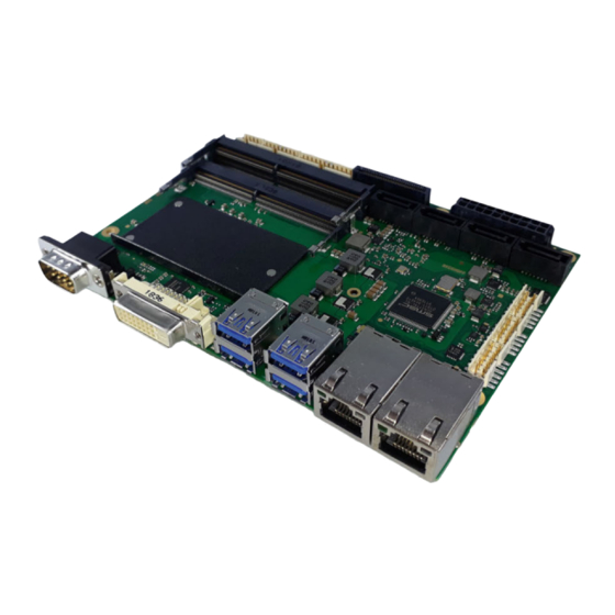
Overview Properties The CB3067 is a highly complex 3.5-inch board. It is based on Intel®'s Coffee-Lake S-processors of the Core™, Celeron™ and Pentium families in conjunction with the Q370 chipset. State-of-the-art, energy-saving DDR4 technology enables a memory extension of up to 32 GB (DDR4-2666) using SO-DIMM260. -
Page 10: List Of Features
Overview List of features CB3067 3.5-inch board CPU Intel® Core™ i3 / Core™ i5 / Core™ i7 Intel® Pentium® Intel® Celeron® Chipset Intel® Q370-PCH Memory 2x SO-DIMM260 1.2 V DDR4-2666 Maximum memory extension 32 GB I/O external 1x DVI-D (DVI or HDMI 1.4) 2 x Gbit LAN, Intel®... -
Page 11: Specifications And Documents
• i210 datasheet • www.intel.com • SMSC® chip description • SCH3114 datasheet (NDA required) • www.smsc.com • American Megatrends® • Aptio™ Text Setup Environment (TSE) User Manual • www.ami.com • American Megatrends® • Aptio™ 5.x Status Codes • www.ami.com CB3067 Version: 1.0... -
Page 12: Detailed Description
3.3 V supply be guaranteed. Second UPS The CB3067 can optionally be equipped with a plug-in second UPS, which can maintain the supply of power for a few seconds, depending on its capacitance and the current consumption of the board, in order to compensate brief power failures or voltage fluctuations. -
Page 13: Connections
Connections Connections All the connectors on the CB3067 are described on the following pages. Requirement for the cabling! The cables used must meet certain requirements for most interfaces. For example, twisted and shielded cables are necessary for a reliable USB 2.0 connection. Limitations in the maximum cable length are also no rarity. -
Page 14: Plug Connector Overview
Connections Plug connector overview The illustration below shows the plug connections on the component side of the CB3067 board. The function of the respective connector can be taken from the table below. The listed page in the manual provides you with further information on this connection. -
Page 15: Power Input (P1300)
Connections Power input (P1300) The connection for the power supply of the CB3067 is implemented as a 2x10-pin housing connector. The 12 V supply is required for the operation of PCI-Express cards and the fan connections. COM RXD and TXD can also be used for your own power supply unit, e.g. for the UPS function. -
Page 16: Sata Interfaces (P500/1/2/3)
Connections SATA interfaces (P500/1/2/3) The CB3067 board is equipped with four SATA interfaces, which allow a data transfer rate of up to 6 Gbit per second. The interfaces are available as 7-pin standard SATA connectors. RAID 0/1/5/10 are supported. The necessary settings are made via the BIOS setup. -
Page 17: Fan Connections (P1100)
Three fans with a supply voltage of 12 Volt can be connected to the module. This takes place with a 2x5-pin connector. There are also signals for monitoring the fan speed. Fig. 6: CB3067 fan (P1100) Pin assignment fan connection Description Name... -
Page 18: Display Port Ipex (P1001)
Display port IPEX (P1001) The CB3067 has a further DVI connection, which is implemented in the form of a 30-pin ribbon cable connector. There are no analog VGA signals on this connection, but an HDMI or DisplayPort screen can be connected. -
Page 19: Lan (P900/800)
1000BaseT can be connected to both. The required speed is selected automatically. Auto-Cross and Auto- Negotiate are available as well as PXE and WOL functionality. Controllers are Intel®'s i219 (PHY, LAN1) and i210 (MAC/PHY, LAN2). Fig. 9: CB3067 LAN (P900-800) Pin assignment LAN Description Name... -
Page 20: Usb 3.0 External (P1201/P1203)
Windows with a connected USB mouse and keyboard, because this would result in significant performance limitations. The individual USB interfaces can supply a current of up to 900 mA and are electronically protected. Fig. 10: CB3067-USB3.0 (P1201+1203) Pin assignment USB 3.0 Pin Name... -
Page 21: Dvi-D (P1000)
Connections 6.10 DVI-D (P1000) The board has a DVI-D connection for DVI-capable displays. Analog displays cannot be connected. Fig. 11: CB3067 DVI-D (P1000) Pin assignment of DVI-D Pin Name Description 1 TMDSDAT2# DVI Data 2 - 2 TMDSDAT2 DVI Data 2 + 3... -
Page 22: Serial Interface Com1 (P1200)
The COM1 serial interface is fed out via a 9-pin standard DSUB connector (male). The signals are available according to the RS232 standard. The port address and the interrupt used are set with the help of the BIOS setup. Fig. 12: CB3067 COM1 (P1200) Pin assignment of COM1 Description Name... -
Page 23: Memory So-Dimm260 (U601/U600)
6.12 Memory SO-DIMM260 (U601/U600) On the CB3067 board there are two SO-DIMM260 memory slots for DDR4-2666 RAM. For technical and mechanical reasons, it is possible that certain memory modules cannot be used. Information regarding the recommended memory modules can be obtained from your distributor. - Page 24 Data line 31 Ground GND GND Ground Data line 26 DQ26 DQ27 Data line 27 Ground GND GND Ground Not connected CB5/NC CB4/NC Not connected Ground GND GND Ground Not connected CB1/NC CB0/NC Not connected Ground GND GND Ground Version: 1.0 CB3067...
- Page 25 GND GND Ground Data line 33 DQ33 DQ32 Data line 32 Ground GND GND Ground Data strobe 4 - DQS4# DQM4 Data Mask 4 Data strobe 4 + DQS4 GND Ground Ground GND DQ39 Data line 39 CB3067 Version: 1.0...
- Page 26 Data line 59 Ground GND GND Ground SMBus Clock SCL SDA SMBus Data I²C power for SPD EEProm VCCSPD SA0 SPD Address 0 DRAM Activating Power VPP M_VTT Termination voltage DRAM Activating Power VPP SA1 SPD Address 1 Version: 1.0 CB3067...
-
Page 27: Usb 2.0 Internal (P1202/P1204)
Windows with a USB mouse and keyboard connected, because this would lead to considerable performance limitations. The individual USB interfaces can supply a current of up to 500 mA and are electronically protected. Fig. 14: CB3067 USB 2.0 (P1204) Pin assignment 2x8-pin connector USB 9 - 12 Description Name... -
Page 28: System Connector (P1102)
GPIOs. Of these three LEDs, LED1 and LED2 are already equipped with series resistors. The pin assignment is designed so that associated pins are located opposite or near to each other. Fig. 16: CB3067 system connector (P1102) Pin assignment system connector Description... -
Page 29: Pci-Express Connector (P1101)
6.15 PCI-Express connector (P1101) The CB3067 is equipped with a vendor-specific 2x40-pin connector, via which PCI-Express devices can be connected. Either up to four PCIe1x devices or precisely one PCIe x4 device can be connected. Adapter cards with standard PCIe slots as well as with PCIe Mini-Card connectors are available as accessories. - Page 30 PCIe Clock 4 - Transmit Lane 4 - PET4# 74 GND Ground Ground GND 76 PER4 Receive Lane 4 + Clock Enable 4 - PRSNT4# 78 PER4# Receive Lane 4 - PCIe configuration x1/x4 PECONF x1/ 80 GND Ground x4 Version: 1.0 CB3067...
-
Page 31: Status Leds
Status LEDs Status LEDs RGB LED There is an RGB LED on the CB3067 with which status messages of the power controller are output by means of colors and flashing intervals. Color Interval Meaning None Steadily lit System in error state White... -
Page 32: Bios Settings
It should also be noted that the settings shown in the setup menus below are not necessarily the recommended or default settings. Which settings must be selected depends on the application scenario in which the board is operated. Version: 1.0 CB3067... -
Page 33: Main
BIOS settings Main Aptio Setup Utility - Copyright (C) 2020 American Megatrends, Inc. Main Advanced Chipset Security Boot Save & Exit ┌─────────────────────────────────────────────────────────────────┬────────────────────────────────┐ │ │Set the Date. Use Tab to │ │ Board Information │switch between Date elements. │ │ Board CB3067 │Default Ranges: │ │ Revision 1 │Year: 2005─2099 │ │ Bios Version 0.13 │Months: 1─12 │ │ │Days: dependent on month │ │ Processor Information │ │ │ Name CoffeeLake DT │ │ │ Type Intel(R) Core(TM) │ │ │ i3─9100E CPU @ 3.10GHz │ │ │ Speed 3100 MHz │ │ │ ID 0x906ED │ │ │ Stepping R0 │────────────────────────────────│ │ Number of Processors 4Core(s) / 4Thread(s) │→←: Select Screen │ │ Microcode Revision AA │↑↓: Select Item │ │ GT Info GT2 (0x3E98) │Enter: Select │ │ │+/─: Change Opt. │ │ IGFX VBIOS Version N/A │F1: General Help │ │ IGFX GOP Version 9.0.1105 │F2: Previous Values │ │ Memory RC Version 0.7.1.112 │F3: Optimized Defaults │ │ Total Memory 4096 MB │F4: Save & Reset │ │ Memory Frequency 2133 MHz │ESC: Exit │ │ │ │ │ PCH Information │ │ │ Name CNL PCH─H │ │ │ Stepping BO │ │ │ │ │ │ ME FW Version 12.0.55.1521 │ │ │ │ │ │ System Date [Tue 06/03/2020] │ │ │ System Time [04:00:35] │ │ └─────────────────────────────────────────────────────────────────┴────────────────────────────────┘ Version 2.20.1275. Copyright (C) 2020 American Megatrends, Inc. Bios entry Option... -
Page 34: Advanced Menu
Submenu see: Network Stack Configuration [} 59] Intel(R) I210 Gigabit Network Submenu see: NIC Configuration [} 62] Connection 00:01:05:52:C3:3D Intel® Rapid Store Technology Submenu see: Intel Rapid Storage Technology [} 63] Intel(R) Ethernet Connection (2) Submenu see: NIC Configuration [} 65] I219LM 00:01:05:52:C7:3C Driver Health Submenu see: Driver Health [} 66] Version: 1.0 CB3067... -
Page 35: Rc Acpi Settings
Version 2.20.1275. Copyright (C) 2020 American Megatrends, Inc. Bios entry Options RC ACPI settings PTID support Enabled / Disabled PECI access method Direct I / O Native PCIE Enable Enabled / Disabled PUIS Enable None MSI enabled Enabled / Disabled CB3067 Version: 1.0... -
Page 36: Cpu Configuration
Hardware prefetcher Enabled / Disabled Adjacent Cache Line Prefetch Enabled / Disabled Intel (VMX) Virtualization Technology Enabled / Disabled PECI Enabled / Disabled Active Processor Cores All / 1 / 2 / 3 AES Enabled / Disabled Version: 1.0 CB3067... -
Page 37: Trusted Computing
8.3.4 ACPI Settings Enabled Aptio Setup Utility - Copyright (C) 2020 American Megatrends, Inc. Advanced ┌─────────────────────────────────────────────────────────────────┬────────────────────────────────┐ │ ACPI Settings │Enables or Disables System │ │ │ability to Hibernate (OS/S4 │ │ Enable ACPI Auto Configuration [Enabled] │Sleep State). This option may │ │ │not be effective with some │ │ │operating systems. │ │ │ │ │ ├────────────────────────────────┤ │ │><: Select Screen │ │ │^v: Select Item │ │ │Enter: Select │ │ │+/─: Change Opt. │ │ │F1: General Help │ │ │F2: Previous Values │ │ │F3: Optimized Defaults │ │ │F4: Save & Reset │ │ │ESC: Exit │ └─────────────────────────────────────────────────────────────────┴────────────────────────────────┘ Version 2.20.1275. Copyright (C) 2020 American Megatrends, Inc. Bios entry Options ACPI Settings Enable ACPI Auto Configuration Disabled / Enabled CB3067 Version: 1.0... -
Page 38: Acpi Settings Disabled
│ Lock Legacy Resources [Disabled] │ │ │ ├────────────────────────────────┤ │ │→←: Select Screen │ │ │↑↓: Select Item │ │ │Enter: Select │ │ │+/─: Change Opt. │ │ │F1: General Help │ │ │F2: Previous Values │ │ │F3: Optimized Defaults │ │ │F4: Save & Reset │ │ │ESC: Exit │ │ │ │ └─────────────────────────────────────────────────────────────────┴────────────────────────────────┘ Version 2.20.1275. Copyright (C) 2020 American Megatrends, Inc. Bios entry Options ACPI Settings Enable ACPI Auto Configuration Enabled / Disabled Enabale Hibernation Disabled / Enabled Lock Legacy Resources Disabled / Enabled Version: 1.0 CB3067... -
Page 39: Sch3114 Super Io Configuration
│ │→←: Select Screen │ │ │↑↓: Select Item │ │ │Enter: Select │ │ │+/─: Change Opt. │ │ │F1: General Help │ │ │F2: Previous Values │ │ │F3: Optimized Defaults │ │ │F4: Save & Reset │ │ │ESC: Exit │ │ │ │ └─────────────────────────────────────────────────────────────────┴────────────────────────────────┘ Version 2.20.1275. Copyright (C) 2020 American Megatrends, Inc. Bios entry Options Serial Port 1 Configuration Serial Port Enabled / Disabled Device Settings None Change Settings Auto / IO=3F8h; IRQ=4;…IO=2E8h; IRQ=3,4,5,6,7,9,10,11,12; Device Mode Normal / High Speed CB3067 Version: 1.0... - Page 40 │ │→←: Select Screen │ │ │↑↓: Select Item │ │ │Enter: Select │ │ │+/─: Change Opt. │ │ │F1: General Help │ │ │F2: Previous Values │ │ │F3: Optimized Defaults │ │ │F4: Save & Reset │ │ │ESC: Exit │ │ │ │ └─────────────────────────────────────────────────────────────────┴────────────────────────────────┘ Version 2.20.1275. Copyright (C) 2020 American Megatrends, Inc. Bios entry Options Serial Port 2 Configuration Serial Port Enabled / Disabled Device Settings None Change Settings Auto / IO=2F8h; IRQ=3;…IO=2E8h; IRQ=3,4,5,6,7,9,10,11,12; Device Mode Normal / High Speed Version: 1.0 CB3067...
-
Page 41: Hardware Monitor
Hardware Monitor Aptio Setup Utility - Copyright (C) 2020 American Megatrends, Inc. Advanced ┌─────────────────────────────────────────────────────────────────┬────────────────────────────────┐ │ Pc Health Status │ │ │ │control │ │ CPU dig. : +100 'C │ │ │ VCCCORE : +0.80 V │ │ │ 5V : +4.97 V │ │ │ 12V : +12.06 V │ │ │ VBATT : +0.5 V │ │ │ 3.3V : +3.26 V │ │ │ SIO Temp : +61 V │ │ │ 1.05V : +1.06 V │ │ │ Memory VDD : +1.26 V │ │ │ FAN 1 : N/A │ │ │ FAN 2 : N/A │ │ │ FAN 3 : N/A │ │ │ MB Temp : +57 'C │ │ │ Memory Temp : +66 'C ├────────────────────────────────│ │ PwrCtrlTemp : +59 'C │→←: Select Screen │ │ PwrCtrlVCC : +5.00 V │↑↓: Select Item │ │ │Enter: Select │ │ │+/─: Change Opt. │ │ │F1: General Help │ │ │F2: Previous Values │ │ │F3: Optimized Defaults │ │ │F4: Save & Reset │ │ │ESC: Exit │ └─────────────────────────────────────────────────────────────────┴────────────────────────────────┘ Version 2.20.1275. Copyright (C) 2020 American Megatrends, Inc. Bios entry Options PC Health Status None CB3067 Version: 1.0... -
Page 42: Serial Port Console Redirection
Disabled / Enabled Console Redirection Settings Submenu see: COM0 Console Redirection Settings [} 43] COM1 Console Redirection Disabled / Enabled Console Redirection Settings Submenu see: COM1 Console Redirection Settings [} 44] Com4 (Pci Bus0, Dev0, Func0) (Disabled) Console Redirection None Version: 1.0 CB3067... - Page 43 1 / 2 Flow Control None / Hardware RTS/CTS VT-UTF8 Combo Key Support Enabled / Disabled Recorder Mode Disabled / Enabled Resolution 100x31 Disabled / Enabled Putty KeyPad VT100 / LINUX / XTERMR6 / SCO / ESCN / VT400 CB3067 Version: 1.0...
- Page 44 1 / 2 Flow Control None / Hardware RTS/CTS VT-UTF8 Combo Key Support Enabled / Disabled Recorder Mode Disabled / Enabled Resolution 100x31 Disabled / Enabled Putty KeyPad VT100 / LINUX / XTERMR6 / SCO / ESCN / VT400 Version: 1.0 CB3067...
-
Page 45: Ami Graphic Output Protocol Policy
8.3.9 AMI Graphic Output Protocol Policy Aptio Setup Utility - Copyright (C) 2020 American Megatrends, Inc. Advanced ┌─────────────────────────────────────────────────────────────────┬────────────────────────────────┐ │ Intel(R) Graphics Controller │Output Interface │ │ Intel(R) GOP Driver [9.0.1105] │ │ │ Output Select [DVI1] │ │ │ ├────────────────────────────────┤ │ │→←: Select Screen │ │ │↑↓: Select Item │ │ │Enter: Select │ │ │+/─: Change Opt. │ │ │F1: General Help │ │ │F2: Previous Values │ │ │F3: Optimized Defaults │ │ │F4: Save & Reset │ │ │ESC: Exit │ └─────────────────────────────────────────────────────────────────┴────────────────────────────────┘ Version 2.20.1275. Copyright (C) 2020 American Megatrends, Inc. Bios entry Options Intel® Graphics Controller Intel® GOP Driver [9.0.1105] Output Select None CB3067 Version: 1.0... -
Page 46: Pci Subsystem Settings
32 / 64 / 96 / 128 / 160 /192 / 224 / 248 / PCI Bus Clocks VGA Palette Snoop Disabled / Enabled PERR# Generation Disabled / Enabled SERR# Generation Disabled / Enabled Above 4G Decoding Disabled / Enabled PCI Hot-Plug Settings Submenu see: PCI Hot-Plug Settings [} 47] Version: 1.0 CB3067... - Page 47 Disabled / 1 M / 2 M / 4 M / 8 M / 16 M / 32 M / 64 M / 128 M PFMMIO 32 bit Resources Padding Disabled / 1 M / 2 M / 4 M / 8 M / 16 M / 32 M / 64 M / 128 M CB3067 Version: 1.0...
-
Page 48: Usb Configuration
USB Mass Storage Driver Support Enabled / Disabled USB hardware delays and time-outs: USB transfer time-out 1 / 5 / 10 / 20 sec Device reset time-out 10 / 20 / 30 / 40 sec Device power-up delay Auto / Manual Version: 1.0 CB3067... -
Page 49: Nvme Configuration
┌─────────────────────────────────────────────────────────────────┬────────────────────────────────┐ │ NVMe controller and Drive information │ │ │ │ │ │ No NVME Device Found │ │ │ ├────────────────────────────────┤ │ │→←: Select Screen │ │ │↑↓: Select Item │ │ │Enter: Select │ │ │+/─: Change Opt. │ │ │F1: General Help │ │ │F2: Previous Values │ │ │F3: Optimized Defaults │ │ │F4: Save & Reset │ │ │ESC: Exit │ │ │ │ └─────────────────────────────────────────────────────────────────┴────────────────────────────────┘ Version 2.20.1275. Copyright (C) 2020 American Megatrends, Inc. Bios entry Options NVMe controller and Drive Information No NVME Device Found None NOTE NVMe Raid 0/1 is not supported. CB3067 Version: 1.0... -
Page 50: Power Controller Options
Mainboard BootCount None Mainboard operation time None Voltage (Min/Max) None Temperature (Min/Max) None ext. USB port voltage Off in S3-5 / by SCVV int. USB port voltage Off in S3-5 / by SCVV WatchDogTimer mode Normal Mode / Compatibility Mode WDT OSBoot Timeout Disabled / 45, 60, 75,…225, 240, 255 seconds Version: 1.0 CB3067... -
Page 51: Sata Und Rst Configuration
HDD / SSD SATA Port 0 DevSlp Disabled / Enabled DITO Configuration Disabled / Enabled NOTE Settings on SATA ports 0 - 3 The possible settings on SATA ports 0-3 are identical. Therefore, these are summarized in the illustration. CB3067 Version: 1.0... - Page 52 Smart Response Technology Enabled / Disabled OROM UI Normal Delay 2, 4, 6, 8 secs RST Force Form Disabled / Enabled System Acceleration with Intel(R) Enabled / Disabled Optane (TM) Memory CPU Attached Storage Enabled / Disabled Version: 1.0 CB3067...
-
Page 53: Amt Configuration
Submenu see: ASF Configuration [} 55] Secure Erase Configuration Submenu see: Secure Erase Configuration [} 55] OEM Flags Settings Submenu see: OEM Flags Settings [} 56] MEBx Resolution Settings Submenu see: MEBx Resolution Settings [} 57] Headless mode Disabled / Enabled CB3067 Version: 1.0... - Page 54 │ CIRA Timeout 0 │Note: │ │ │Network Access must be │ │ │activated first from MEBx │ │ │Setup. │ │ ├────────────────────────────────┤ │ │→←: Select Screen │ │ │↑↓: Select Item │ │ │Enter: Select │ │ │+/─: Change Opt. │ │ │F1: General Help │ │ │F2: Previous Values │ │ │F3: Optimized Defaults │ │ │F4: Save & Reset │ │ │ESC: Exit │ │ │ │ └─────────────────────────────────────────────────────────────────┴────────────────────────────────┘ Version 2.20.1275. Copyright (C) 2020 American Megatrends, Inc. Bios entry Options Activate Remote Assistance Process Disabled / Enabled CIRA Timeout None Version: 1.0 CB3067...
- Page 55 Advanced ┌─────────────────────────────────────────────────────────────────┬────────────────────────────────┐ │ Secure Erase mode [Simulated] │Change Secure Erase module │ │ Force Secure Erase [Disabled] │behavior: │ │ │Simulated: Performs SE flow │ │ │without erasing SSD │ │ │Real: Erase SSD. │ │ │ │ │ ├────────────────────────────────┤ │ │→←: Select Screen │ │ │↑↓: Select Item │ │ │Enter: Select │ │ │+/─: Change Opt. │ │ │F1: General Help │ │ │F2: Previous Values │ │ │F3: Optimized Defaults │ │ │F4: Save & Reset │ │ │ESC: Exit │ │ │ │ │ │ │ └─────────────────────────────────────────────────────────────────┴────────────────────────────────┘ Version 2.20.1275. Copyright (C) 2020 American Megatrends, Inc. Bios entry Options Secure Erase Mode Simulated / Real Force Secure Erase Disabled / Enabled CB3067 Version: 1.0...
- Page 56 Version 2.20.1275. Copyright (C) 2020 American Megatrends, Inc. Bios entry Options MBEx hotkey Pressed Disabled / Enabled MBEx Selection Screen Disabled / Enabled Hide Unconfigure ME Confirmation Prompt Disabled / Enabled MBEx OEM Debug Menu Enable Disabled / Enabled Unconfigure ME Disabled / Enabled Version: 1.0 CB3067...
-
Page 57: Tls Auth Configuration
TLs Auth Configuration Aptio Setup Utility - Copyright (C) 2020 American Megatrends, Inc. Advanced ┌─────────────────────────────────────────────────────────────────┬────────────────────────────────┐ │ │Press <Enter> to configure │ │> Server CA Configuration │Server CA. │ │ │ │ │> Client Cert Configuration │ │ │ ├────────────────────────────────┤ │ │→←: Select Screen │ │ │↑↓: Select Item │ │ │Enter: Select │ │ │+/─: Change Opt. │ │ │F1: General Help │ │ │F2: Previous Values │ │ │F3: Optimized Defaults │ │ │F4: Save & Reset │ │ │ESC: Exit │ └─────────────────────────────────────────────────────────────────┴────────────────────────────────┘ Version 2.20.1275. Copyright (C) 2020 American Megatrends, Inc. Bios entry Options Server CA Configuration Submenu see: Server CA Configuration [} 58] Client Cert Configuration None CB3067 Version: 1.0... - Page 58 │ Cert GUID │ │ │> Commit Changes and Exit │ │ │> Discard Changes and Exit │ │ │ ├────────────────────────────────┤ │ │><: Select Screen │ │ │^v: Select Item │ │ │Enter: Select │ │ │+/─: Change Opt. │ │ │F1: General Help │ │ │F2: Previous Values │ │ │F3: Optimized Defaults │ │ │F4: Save & Reset │ │ │ESC: Exit │ └─────────────────────────────────────────────────────────────────┴────────────────────────────────┘ Version 2.20.1271. Copyright (C) 2019 American Megatrends, Inc. Bios entry Options Enroll CertEnroll Cert Using File None Cert GUID None Commit Changes and Exit None Discard Changes and Exit None Version: 1.0 CB3067...
-
Page 59: Network Stack Configuration
BIOS settings 8.3.17 Network Stack Configuration Aptio Setup Utility - Copyright (C) 2020 American Megatrends, Inc. Advanced ┌─────────────────────────────────────────────────────────────────┬────────────────────────────────┐ │ Network Stack [Disabled] │Enable/Disable UEFI Network │ │ │Stack │ │ │ │ │ ├────────────────────────────────┤ │ │→←: Select Screen │ │ │↑↓: Select Item │ │ │Enter: Select │ │ │+/─: Change Opt. │ │ │F1: General Help │ │ │F2: Previous Values │ │ │F3: Optimized Defaults │ │ │F4: Save & Reset │ │ │ESC: Exit │ │ │ │ └─────────────────────────────────────────────────────────────────┴────────────────────────────────┘ Version 2.20.1275. Copyright (C) 2020 American Megatrends, Inc. Bios entry Options Network Stack Disabled / Enabled CB3067 Version: 1.0... -
Page 60: Network Stack Configuration Enabled
Ipv6 HTTP Support Disabled / Enabled IPSEC Certificate Enabled / Disabled PXE boot wait time None Media detect count None NOTE PXE Boot available PXE Boot is available if you set Network Stack and Ipv4 PXE support to "Enable". Version: 1.0 CB3067... -
Page 61: Intel I210 Gigabit Network Connection
Submenu see: NIC Configuration [} 62] Flashing LEDs None UEFI driver None PBA adapter None Device Name None Chip type None PCI Device ID None PCI Address None Link status None MAC Address None Virtual MAC Address None CB3067 Version: 1.0... - Page 62 │ │F1: General Help │ │ │F2: Previous Values │ │ │F3: Optimized Defaults │ │ │F4: Save & Reset │ │ │ESC: Exit │ │ │ │ └─────────────────────────────────────────────────────────────────┴────────────────────────────────┘ Version 2.20.1275. Copyright (C) 2020 American Megatrends, Inc. Bios entry Options Link Speed Auto Negotiated / 10 Mbps Half / 10 Mbps Full / 100 Mbps Half / 100 Mbps Full Wake On LAN Disabled / Enabled Version: 1.0 CB3067...
-
Page 63: Intel Rapid Storage Technology
8.3.20 Intel Rapid Storage Technology Aptio Setup Utility - Copyright (C) 2020 American Megatrends, Inc. Advanced ┌─────────────────────────────────────────────────────────────────┬────────────────────────────────┐ │ Intel (R) RST 17.8.0.4414 RAID Driver │ │ │ │ │ │ No disks connected to system │ │ │ ├────────────────────────────────┤ │ │→←: Select Screen │ │ │↑↓: Select Item │ │ │Enter: Select │ │ │+/─: Change Opt. │ │ │F1: General Help │ │ │F2: Previous Values │ │ │F3: Optimized Defaults │ │ │F4: Save & Reset │ │ │ESC: Exit │ └─────────────────────────────────────────────────────────────────┴────────────────────────────────┘ Version 2.20.1275. Copyright (C) 2020 American Megatrends, Inc. Bios entry Options Intel® RST 17.8.0.4414 RAID Driver No disks connected to system None CB3067 Version: 1.0... -
Page 64: Intel Ethernet Connection(2) I219-Lm
PORT CONFIGURATION MENU NIC Configuration See submenu: NIC Configuration [} 65] Flashing LEDs None PORT CONFIGURATION INFORMATION UEFI driver None PBA adapter None Chip type None PCI Device ID None PCI Address None Link status None MAC Address None Version: 1.0 CB3067... - Page 65 │ │F1: General Help │ │ │F2: Previous Values │ │ │F3: Optimized Defaults │ │ │F4: Save & Reset │ │ │ESC: Exit │ │ │ │ └─────────────────────────────────────────────────────────────────┴────────────────────────────────┘ Version 2.20.1275. Copyright (C) 2020 American Megatrends, Inc. Bios entry Options Link Speed Auto Negotiated / 10 Mbps Half / 10 Mbps Full / 100 Mbps Half / 100 Mbps Full Wake On LAN Disabled / Enabled CB3067 Version: 1.0...
-
Page 66: Driver Health
8.3.22 Driver Health Aptio Setup Utility - Copyright (C) 2020 American Megatrends, Inc. Advanced ┌─────────────────────────────────────────────────────────────────┬────────────────────────────────┐ │> Intel(R) Gigabit 0.0.24 Healthy │Provides Health Status for the │ │> Intel(R) PRO/1000 7.3.20 PCI─E Healthy │Drivers/Controllers │ │ │ │ │ │ │ │ ├────────────────────────────────┤ │ │><: Select Screen │ │ │^v: Select Item │ │ │Enter: Select │ │ │+/─: Change Opt. │ │ │F1: General Help │ │ │F2: Previous Values │ │ │F3: Optimized Defaults │ │ │F4: Save & Reset │ │ │ESC: Exit │ │ │ │ └─────────────────────────────────────────────────────────────────┴────────────────────────────────┘ Version 2.20.1275. Copyright (C) 2020 American Megatrends, Inc. Bios entry Options Intel(R) Gigabit 0.0.24 Healthy None Intel(R) PRO/1000 7.3.20 PCI-E Healthy None Version: 1.0 CB3067... -
Page 67: Chipset
┌─────────────────────────────────────────────────────────────────┬────────────────────────────────┐ │> System Agent (SA) Configuration │System Agent (SA) Parameters │ │> PCH─IO Configuration │ │ │ ├────────────────────────────────┤ │ │><: Select Screen │ │ │^v: Select Item │ │ │Enter: Select │ │ │+/─: Change Opt. │ │ │F1: General Help │ │ │F2: Previous Values │ │ │F3: Optimized Defaults │ │ │F4: Save & Reset │ │ │ESC: Exit │ │ │ │ └─────────────────────────────────────────────────────────────────┴────────────────────────────────┘ Version 2.20.1275. Copyright (C) 2020 American Megatrends, Inc. Bios entry Options System Agent (SA) Configuration Submenu see: System Agent (SA) Configuration [} 68] PCH-IO Configuration Submenu see: PCH-IO Configuration [} 70] CB3067 Version: 1.0... -
Page 68: System Agent (Sa) Configuration
Thermal device (B0:D4:F0) Enabled / Disabled GNA device (B0:D8:F0) Enabled / Disabled CRID support Disabled / Enabled Above 4GB MMIO BIOS assignment Disabled / Enabled X2APIC Opt Out Disabled / Enabled IPU device (B0:D5:F0) Disabled / Enabled Version: 1.0 CB3067... - Page 69 Intel Graphics Pei Display Peim Disabled / Enabled VDD Enable Enabled / Disabled PM Support None PAVP Enable Enabled / Disabled Cdynmax Clamping Enable Enabled / Disabled Cd Clock Frequency 337.5 / 450 / 540 / 675 Mhz CB3067 Version: 1.0...
-
Page 70: Pch-Io Configuration
Enabled / Disabled PS_ON Enable Disabled / Enabled CLKRUN# logic Enabled / Disabled State after G3 S0 state / S5 state Compatible revision ID None Legacy IO low latency Enabled / Disabled Enable TCO timer Disabled / Enabled Version: 1.0 CB3067... - Page 71 PCIE Port 5 is assigned to LAN1 None PCI express root port 9 Disabled / Enabled PCI express root port 10 Disabled / Enabled PCI express root port 11 Disabled / Enabled PCI express root port 12 Disabled / Enabled CB3067 Version: 1.0...
- Page 72 │ Gen3 Eq Phase3 Method [Hardware] │ │ │ UPTP 5 │ │ │ DPTP 7 │ │ │ ACS [Enabled] │ │ │ PTM [Enabled] │ │ │ DPC [Enabled] │ │ │ EDPC [Enabled] │ │ │ URR [Disabled] │ │ │ FER [Disabled] ├────────────────────────────────┤ ┤ NFER [Disabled] │→←: Select Screen │ │ CER [Disabled] │↑↓: Select Item │ │ CTO [Disabled] │Enter: Select │ │ SEFE [Disabled] │+/─: Change Opt. │ │ SENFE [Disabled] │F1: General Help │ │ SECE [Disabled] │F2: Previous Values │ │ PME SCI [Enabled] │F3: Optimized Defaults │ │ Hot Plug [Disabled] │F4: Save & Reset │ │ Advanced Error Reporting [Enabled] │ESC: Exit │ │ PCIe Speed [Auto] │ │ │ Transmitter Half Swing [Disabled] │ │ │ Detect Timeout 0 │ │ │ Extra Bus Reserved 0 │ │ │ Reserved Memory 10 │ │ │ Reserved I/O 4 │ │ │ │ │ │ PCH PCIe LTR Congguration │ │ │ LTR [Enabled] │ │ │ Snoop Latency Override [Auto] │ │ │ Non Snoop Latency Override [Auto] │ │ │ Force LTR Override [Disabled] │ │ │ │ │ │ LTR Lock [Disabled] │ │ │ │ │ │ >Extra Options │ │ │ │ │ └─────────────────────────────────────────────────────────────────┴────────────────────────────────┘ Version 2.20.1275. Copyright (C) 2020 American Megatrends, Inc. Version: 1.0 CB3067...
- Page 73 Disabled / Enabled LTR Lock Disabled / Enabled Extra Options Submenu see: Extra Options [} 74] NOTE PCI Express Configuration The BIOS entries and the options on ports 9 – 12 are identical. Port 9 is shown as an example. CB3067 Version: 1.0...
- Page 74 │ Detect Non─Comliance Device [Disabled] │Detect Non─Compliance PCI │ │ Prefetchable Memory 10 │Express Device. If enable, it │ │ Reserved Memory Alignment 1 │will take more time at POST │ │ Prefetchable Memory Alignment 1 │time. │ │ │────────────────────────────────│ │ │→←: Select Screen │ │ │↑↓: Select Item │ │ │Enter: Select │ │ │+/─: Change Opt. │ │ │F1: General Help │ │ │F2: Previous Values │ │ │F3: Optimized Defaults │ │ │F4: Save & Reset │ │ │ESC: Exit │ │ │ │ └─────────────────────────────────────────────────────────────────┴────────────────────────────────┘ Version 2.20.1275. Copyright (C) 2020 American Megatrends, Inc. BIOS entry Options Detect non-compliance device Disabled / Enabled Prefetchable Memory None Reserved Memory Alignment None Prefetchable Memory Alignment None Version: 1.0 CB3067...
- Page 75 HD Audio Configuration Aptio Setup Utility - Copyright (C) 2020 American Megatrends, Inc. Chipset ┌─────────────────────────────────────────────────────────────────┬────────────────────────────────┐ │ HD Audio Subsystem Configuration Settings │Control Detection of the │ │ │HD─Audio device. │ │ HD Audio [Enabled] │Disabled = HDA will be │ │ │unconditionally disabled │ │ │Enabled = HDA will be │ │ │unconditionally enabled. │ │ │ │ │ ├────────────────────────────────┤ │ │→←: Select Screen │ │ │↑↓: Select Item │ │ │Enter: Select │ │ │+/─: Change Opt. │ │ │F1: General Help │ │ │F2: Previous Values │ │ │F3: Optimized Defaults │ │ │F4: Save & Reset │ │ │ESC: Exit │ │ │ │ └─────────────────────────────────────────────────────────────────┴────────────────────────────────┘ Version 2.20.1275. Copyright (C) 2020 American Megatrends, Inc. Bios entry Options HD audio subsystem configuration settings HD audio Enabled / Disabled CB3067 Version: 1.0...
-
Page 76: Security
│ │Enter: Select │ │ │+/─: Change Opt. │ │ │F1: General Help │ │ │F2: Previous Values │ │ │F3: Optimized Defaults │ │ │F4: Save & Reset │ │ │ESC: Exit │ │ │ │ └─────────────────────────────────────────────────────────────────┴────────────────────────────────┘ Version 2.20.1275. Copyright (C) 2020 American Megatrends, Inc. Setup entry Options Password Description Minimum length None Maximum length None Administrator Password Here you can set an administrator password. Secure Boot Submenu see: Secure Boot [} 77] Version: 1.0 CB3067... -
Page 77: Secure Boot
Disabled / Enabled Not Active Secure Boot Mode Custom / Standard Restore factory keys Submenu see: Restore factory keys [} 78] Reset To Setup Mode Submenu see: Reset To Setup Mode [} 79] Key Management Submenu see: Key Management [} 80] CB3067 Version: 1.0... - Page 78 │ │───────────────────────────────────────│ elect Screen │ │ │ Yes No │ elect Item │ │ └───────────────────────────────────────┘ : Select │ │ Change Opt. │ │ │F1: General Help │ │ │F2: Previous Values │ │ │F3: Optimized Defaults │ │ │F4: Save & Reset │ │ │ESC: Exit │ │ │ │ └─────────────────────────────────────────────────────────────────┴────────────────────────────────┘ Version 2.20.1275. Copyright (C) 2020 American Megatrends, Inc. Bios entry Options System Mode None Secure Boot Disabled / Enabled Secure Boot Mode Custom / Standard Restore factory keys Install factory defaults, see box Version: 1.0 CB3067...
- Page 79 │ eneral Help │ │ │F2: Previous Values │ │ │F3: Optimized Defaults │ │ │F4: Save & Reset │ │ │ESC: Exit │ │ │ │ └─────────────────────────────────────────────────────────────────┴────────────────────────────────┘ Version 2.20.1275. Copyright (C) 2020 American Megatrends, Inc. Bios entry Options System Mode none Secure Boot Disabled / Enabled Not Active Secure Boot Mode Custom / Standard Reset To Setup Mode Reset To Setup Mode (see box) CB3067 Version: 1.0...
- Page 80 Submenu see: Restore DB faults [} 84] Secure Boot variables Press enter key PlatformKey(PK) Press enter key Key Exchange Keys Press enter key Authorized Signatures Press enter key Forbidden Signatures Press enter key Authorized TimeStamps Press enter key OsRecovery Signatures Press enter key Version: 1.0 CB3067...
- Page 81 │ Factory Key Provision [Disabled] │Boot key databases │ │> Restore Factory Keys │ │ │> Reset To Setup Mode │ │ │> Export Secure Boot variables │ │ │> Enroll Efi Image │ │ │ │ │ │ Device Guard Ready │ │ │> Remove 'UEFI CA' from DB ┌─────── Install factory defaults ──────┐ │ │> Restore DB defaults │ │ │ │ │ Press 'Yes' to proceed 'No' to cancel │ │ │ Secure Boot variable │ Siz│ │ ───────────────────────────│ │> Platform Key(PK) │ 86│───────────────────────────────────────│ elect Screen │ │> Key Exchange Keys │ 156│ Yes No │ elect Item │ │> Authorized Signatures│ 314└───────────────────────────────────────┘ : Select │ │> Forbidden Signatures│ 3724│ Change Opt. │ │> Authorized TimeStamps│ 0│ 0│ No Keys │F1: General Help │ │> OsRecovery Signatures│ 0│ 0│ No Keys │F2: Previous Values │ │ │F3: Optimized Defaults │ │ │F4: Save & Reset │ │ │ESC: Exit │ │ │ │ └─────────────────────────────────────────────────────────────────┴────────────────────────────────┘ Version 2.20.1275. Copyright (C) 2020 American Megatrends, Inc. Bios entry Options Vendor Keys None Restore factory keys Restore Factory Keys, see box CB3067 Version: 1.0...
- Page 82 │> Reset To Setup Mode │ │ │> Export Secure Boot variables │ │ │> Enroll Efi Image │ │ │ │ │ │ Device Guard Ready ┌───────── Reset To Setup Mode ─────────┐ │ │> Remove 'UEFI CA' from DB │ │ │ │> Restore DB defaults │ Deleting all variables will reset the │ │ │ │ System to Setup Mode │ │ │ Secure Boot variable │ Siz│ Do you want to proceed? │ ───────────────────────────│ │> Platform Key(PK) │ 86│ │ elect Screen │ │> Key Exchange Keys │ 156│───────────────────────────────────────│ elect Item │ │> Authorized Signatures│ 314│ Yes No │ : Select │ │> Forbidden Signatures│ 372└───────────────────────────────────────┘ Change Opt. │ │> Authorized TimeStamps│ 0│ eneral Help │ │> OsRecovery Signatures│ 0│ 0│ No Keys │F2: Previous Values │ │ │F3: Optimized Defaults │ │ │F4: Save & Reset │ │ │ESC: Exit │ │ │ │ └─────────────────────────────────────────────────────────────────┴────────────────────────────────┘ Version 2.20.1275. Copyright (C) 2020 American Megatrends, Inc. Bios entry Options Vendor Keys None Reset To Setup Mode Reset To Setup Mode, see box Version: 1.0 CB3067...
- Page 83 │> Enroll Efi Image │ │ │ │ │ │ Device Guard Ready │ │ │> Remove 'UEFI CA' from DB ┌─────── Remove 'UEFI CA' from DB ──────┐ │ │> Restore DB defaults │ │ │ │ │ Press 'Yes' to proceed 'No' to cancel │ │ │ Secure Boot variable │ Siz│ │ ───────────────────────────│ │> Platform Key(PK) │ 86│───────────────────────────────────────│ elect Screen │ │> Key Exchange Keys │ 156│ Yes No │ elect Item │ │> Authorized Signatures│ 314└───────────────────────────────────────┘ : Select │ │> Forbidden Signatures│ 3724│ Change Opt. │ │> Authorized TimeStamps│ 0│ 0│ No Keys │F1: General Help │ │> OsRecovery Signatures│ 0│ 0│ No Keys │F2: Previous Values │ │ │F3: Optimized Defaults │ │ │F4: Save & Reset │ │ │ESC: Exit │ │ │ │ └─────────────────────────────────────────────────────────────────┴────────────────────────────────┘ Version 2.20.1275. Copyright (C) 2020 American Megatrends, Inc. Bios entry Options Vendor Keys None Remove ‘UEFI CA’ from DB Remove ‘UEFI CA‘ from DB, see box CB3067 Version: 1.0...
- Page 84 │ Factory Key Provision [Disabled] │ │ │> Restore Factory Keys │ │ │> Reset To Setup Mode │ │ │> Export Secure Boot variables │ │ │> Enroll Efi Image │ │ │ │ │ │ Device Guard Ready │ │ │> Remove 'UEFI CA' from DB ┌───────── Restore DB defaults ─────────┐ │ │> Restore DB defaults │ │ │ │ │ Press 'Yes' to proceed 'No' to cancel │ │ │ Secure Boot variable │ Siz│ │ ───────────────────────────│ │> Platform Key(PK) │ 86│───────────────────────────────────────│ elect Screen │ │> Key Exchange Keys │ 156│ Yes No │ elect Item │ │> Authorized Signatures│ 314└───────────────────────────────────────┘ : Select │ │> Forbidden Signatures│ 3724│ Change Opt. │ │> Authorized TimeStamps│ 0│ 0│ No Keys │F1: General Help │ │> OsRecovery Signatures│ 0│ 0│ No Keys │F2: Previous Values │ │ │F3: Optimized Defaults │ │ │F4: Save & Reset │ │ │ESC: Exit │ │ │ │ └─────────────────────────────────────────────────────────────────┴────────────────────────────────┘ Version 2.20.1275. Copyright (C) 2020 American Megatrends, Inc. Bios entry Options Vendor Keys None Restore DB faults Restore DB Faults, see box Version: 1.0 CB3067...
- Page 85 │ Factory Key Provision [Disabled] │root folder on a file system │ │> Restore Factory Keys │device │ │> Reset To Setup Mode │ │ │> Export Secure Boot variables │ │ │> Enroll Efi Image │ │ │ │ │ │ Device Guard Ready │ │ │> Remove 'UEFI CA' from DB ┌───────── File System ──────────┐ │ │> Restore DB defaults │ │ │ │ │ No Valid File System Available │ │ │ Secure Boot variable │ Size│ K│ │ ──────────────────────────────│ │> Platform Key(PK) │ 862│ │────────────────────────────────│ : Select Screen │ │> Key Exchange Keys │ 1560│ │ Ok │ : Select Item │ │> Authorized Signatures│ 3143│ └────────────────────────────────┘ ter: Select │ │> Forbidden Signatures│ 3724│ 7 ─: Change Opt. │ │> Authorized TimeStamps│ 0│ 0│ No Keys │F1: General Help │ │> OsRecovery Signatures│ 0│ 0│ No Keys │F2: Previous Values │ │ │F3: Optimized Defaults │ │ │F4: Save & Reset │ │ │ESC: Exit │ │ │ │ └─────────────────────────────────────────────────────────────────┴────────────────────────────────┘ Version 2.20.1275. Copyright (C) 2020 American Megatrends, Inc. Bios entry Options Vendor Keys None Export Secure Boot variables File system, see box CB3067 Version: 1.0...
- Page 86 │ Factory Key Provision [Disabled] │ 1.Public Key Certificate: │ │> Restore Factory Keys │ a)EFI_SIGNATURE_LIST │ │> Reset To Setup Mode │ b)EFI_CERT_X509 (DER) │ │> Export Secure Boot variables │ c)EFI_CERT_RSA2048 (bin) │ │> Enroll Efi Image │ d)EFI_CERT_SHAXXX │ │ ┌──────────────────────────────┐│ 2.Authenticated UEFI Variable │ │ Device Guard Ready │ Platform Key(PK) ││ 3.EFI PE/COFF Image(SHA256) │ │> Remove 'UEFI CA' from DB │──────────────────────────────││Key Source: │ │> Restore DB defaults │ Details ││ Factory,External,Mixed │ │ │ Export ││ │ │ Secure Boot variable │ Size│ Ke│ Update ││────────────────────────────────│ │> Platform Key(PK) │ 862│ │ Delete ││→←: Select Screen │ │> Key Exchange Keys │ 1560│ └──────────────────────────────┘│↑↓: Select Item │ │> Authorized Signatures│ 3143│ 2│ Factory │Enter: Select │ │> Forbidden Signatures│ 3724│ 77│ Factory │+/─: Change Opt. │ │> Authorized TimeStamps│ 0│ 0│ No Keys │F1: General Help │ │> OsRecovery Signatures│ 0│ 0│ No Keys │F2: Previous Values │ │ │F3: Optimized Defaults │ │ │F4: Save & Reset │ │ │ESC: Exit │ │ │ │ └─────────────────────────────────────────────────────────────────┴────────────────────────────────┘ Version 2.20.1275. Copyright (C) 2020 American Megatrends, Inc. Bios entry Options Vendor Keys None Platform Key (PK) Platform Key (PK), see box Version: 1.0 CB3067...
- Page 87 │ Factory Key Provision [Disabled] │ 1.Public Key Certificate: │ │> Restore Factory Keys │ a)EFI_SIGNATURE_LIST │ │> Reset To Setup Mode │ b)EFI_CERT_X509 (DER) │ │> Export Secure Boot variables │ c)EFI_CERT_RSA2048 (bin) │ │> Enroll Efi Image │ d)EFI_CERT_SHAXXX │ │ ┌──────────────────────────────┐│ 2.Authenticated UEFI Variable │ │ Device Guard Ready │ Key Exchange Keys ││ 3.EFI PE/COFF Image(SHA256) │ │> Remove 'UEFI CA' from DB │──────────────────────────────││Key Source: │ │> Restore DB defaults │ Details ││ Factory,External,Mixed │ │ │ Export ││ │ │ Secure Boot variable │ Size│ Ke│ Update ││────────────────────────────────│ │> Platform Key(PK) │ 862│ │ Append ││→←: Select Screen │ │> Key Exchange Keys │ 1560│ │ Delete ││↑↓: Select Item │ │> Authorized Signatures│ 3143│ └──────────────────────────────┘│Enter: Select │ │> Forbidden Signatures│ 3724│ 77│ Factory │+/─: Change Opt. │ │> Authorized TimeStamps│ 0│ 0│ No Keys │F1: General Help │ │> OsRecovery Signatures│ 0│ 0│ No Keys │F2: Previous Values │ │ │F3: Optimized Defaults │ │ │F4: Save & Reset │ │ │ESC: Exit │ │ │ │ └─────────────────────────────────────────────────────────────────┴────────────────────────────────┘ Version 2.20.1275. Copyright (C) 2020 American Megatrends, Inc. Bios entry Options Vendor Keys None Key Exchange Keys Key Exchange Keys, see box CB3067 Version: 1.0...
- Page 88 │ Vendor Keys Valid │Enroll Factory Defaults or │ │ │load certificates from a file: │ │ Factory Key Provision [Disabled] │ 1.Public Key Certificate: │ │> Restore Factory Keys │ a)EFI_SIGNATURE_LIST │ │> Reset To Setup Mode │ b)EFI_CERT_X509 (DER) │ │> Export Secure Boot variables │ c)EFI_CERT_RSA2048 (bin) │ │> Enroll Efi Image │ d)EFI_CERT_SHAXXX │ │ ┌──────────────────────────────┐│ 2.Authenticated UEFI Variable │ │ Device Guard Ready │ Authorized Signatures ││ 3.EFI PE/COFF Image(SHA256) │ │> Remove 'UEFI CA' from DB │──────────────────────────────││Key Source: │ │> Restore DB defaults │ Details ││ Factory,External,Mixed │ │ │ Export ││ │ │ Secure Boot variable │ Size│ Ke│ Update ││────────────────────────────────│ │> Platform Key(PK) │ 862│ │ Append ││→←: Select Screen │ │> Key Exchange Keys │ 1560│ │ Delete ││↑↓: Select Item │ │> Authorized Signatures│ 3143│ └──────────────────────────────┘│Enter: Select │ │> Forbidden Signatures│ 3724│ 77│ Factory │+/─: Change Opt. │ │> Authorized TimeStamps│ 0│ 0│ No Keys │F1: General Help │ │> OsRecovery Signatures│ 0│ 0│ No Keys │F2: Previous Values │ │ │F3: Optimized Defaults │ │ │F4: Save & Reset │ │ │ESC: Exit │ │ │ │ └─────────────────────────────────────────────────────────────────┴────────────────────────────────┘ Version 2.20.1275. Copyright (C) 2020 American Megatrends, Inc. Bios entry Options Vendor Keys none Authorized Signatures Authorized Signatures, see box Version: 1.0 CB3067...
- Page 89 │ Vendor Keys Valid │Enroll Factory Defaults or │ │ │load certificates from a file: │ │ Factory Key Provision [Disabled] │ 1.Public Key Certificate: │ │> Restore Factory Keys │ a)EFI_SIGNATURE_LIST │ │> Reset To Setup Mode │ b)EFI_CERT_X509 (DER) │ │> Export Secure Boot variables │ c)EFI_CERT_RSA2048 (bin) │ │> Enroll Efi Image │ d)EFI_CERT_SHAXXX │ │ ┌──────────────────────────────┐│ 2.Authenticated UEFI Variable │ │ Device Guard Ready │ Forbidden Signatures ││ 3.EFI PE/COFF Image(SHA256) │ │> Remove 'UEFI CA' from DB │──────────────────────────────││Key Source: │ │> Restore DB defaults │ Details ││ Factory,External,Mixed │ │ │ Export ││ │ │ Secure Boot variable │ Size│ Ke│ Update ││────────────────────────────────│ │> Platform Key(PK) │ 862│ │ Append ││→←: Select Screen │ │> Key Exchange Keys │ 1560│ │ Delete ││↑↓: Select Item │ │> Authorized Signatures│ 3143│ └──────────────────────────────┘│Enter: Select │ │> Forbidden Signatures│ 3724│ 77│ Factory │+/─: Change Opt. │ │> Authorized TimeStamps│ 0│ 0│ No Keys │F1: General Help │ │> OsRecovery Signatures│ 0│ 0│ No Keys │F2: Previous Values │ │ │F3: Optimized Defaults │ │ │F4: Save & Reset │ │ │ESC: Exit │ │ │ │ └─────────────────────────────────────────────────────────────────┴────────────────────────────────┘ Version 2.20.1275. Copyright (C) 2020 American Megatrends, Inc. Bios entry Options Vendor Keys None Forbidden Signatures Forbidden Signatures, see box CB3067 Version: 1.0...
- Page 90 │ Vendor Keys Valid │Enroll Factory Defaults or │ │ │load certificates from a file: │ │ Factory Key Provision [Disabled] │ 1.Public Key Certificate: │ │> Restore Factory Keys │ a)EFI_SIGNATURE_LIST │ │> Reset To Setup Mode │ b)EFI_CERT_X509 (DER) │ │> Export Secure Boot variables │ c)EFI_CERT_RSA2048 (bin) │ │> Enroll Efi Image │ d)EFI_CERT_SHAXXX │ │ │ 2.Authenticated UEFI Variable │ │ Device Guard Ready ┌──────────────────────────────┐│ 3.EFI PE/COFF Image(SHA256) │ │> Remove 'UEFI CA' from DB │ Authorized TimeStamps ││Key Source: │ │> Restore DB defaults │──────────────────────────────││ Factory,External,Mixed │ │ │ Update ││ │ │ Secure Boot variable │ Size│ Ke│ Append ││────────────────────────────────│ │> Platform Key(PK) │ 862│ └──────────────────────────────┘│><: Select Screen │ │> Key Exchange Keys │ 1560│ 1│ Factory │^v: Select Item │ │> Authorized Signatures│ 3143│ 2│ Factory │Enter: Select │ │> Forbidden Signatures│ 3724│ 77│ Factory │+/─: Change Opt. │ │> Authorized TimeStamps│ 0│ 0│ No Keys │F1: General Help │ │> OsRecovery Signatures│ 0│ 0│ No Keys │F2: Previous Values │ │ │F3: Optimized Defaults │ │ │F4: Save & Reset │ │ │ESC: Exit │ │ │ │ └─────────────────────────────────────────────────────────────────┴────────────────────────────────┘ Version 2.20.1275. Copyright (C) 2020 American Megatrends, Inc. Bios entry Options Vendor Keys none Authorized TimeStamps Authorized TimeStamps, see box Version: 1.0 CB3067...
- Page 91 │ Vendor Keys Valid │Enroll Factory Defaults or │ │ │load certificates from a file: │ │ Factory Key Provision [Disabled] │ 1.Public Key Certificate: │ │> Restore Factory Keys │ a)EFI_SIGNATURE_LIST │ │> Reset To Setup Mode │ b)EFI_CERT_X509 (DER) │ │> Export Secure Boot variables │ c)EFI_CERT_RSA2048 (bin) │ │> Enroll Efi Image │ d)EFI_CERT_SHAXXX │ │ │ 2.Authenticated UEFI Variable │ │ Device Guard Ready ┌──────────────────────────────┐│ 3.EFI PE/COFF Image(SHA256) │ │> Remove 'UEFI CA' from DB │ OsRecovery Signatures ││Key Source: │ │> Restore DB defaults │──────────────────────────────││ Factory,External,Mixed │ │ │ Update ││ │ │ Secure Boot variable │ Size│ Ke│ Append ││────────────────────────────────│ │> Platform Key(PK) │ 862│ └──────────────────────────────┘│→←: Select Screen │ │> Key Exchange Keys │ 1560│ 1│ Factory │↑↓: Select Item │ │> Authorized Signatures│ 3143│ 2│ Factory │Enter: Select │ │> Forbidden Signatures│ 3724│ 77│ Factory │+/─: Change Opt. │ │> Authorized TimeStamps│ 0│ 0│ No Keys │F1: General Help │ │> OsRecovery Signatures│ 0│ 0│ No Keys │F2: Previous Values │ │ │F3: Optimized Defaults │ │ │F4: Save & Reset │ │ │ESC: Exit │ │ │ │ └─────────────────────────────────────────────────────────────────┴────────────────────────────────┘ Version 2.20.1275. Copyright (C) 2020 American Megatrends, Inc. Bios entry Options Vendor Keys none OsRecovery Signatures OsRecovery Signatures, see box CB3067 Version: 1.0...
-
Page 92: Boot
Boot mode select Legacy / UEFI / Dual Fixed Boot Order Priorities Boot Option #1-11 Set here the order of the boot media to be used. Advanced Fixed Boot Order Parameters Submenu see: Fixed Boot Order Parameters [} 93] Version: 1.0 CB3067... -
Page 93: Fixed Boot Order Parameters
Min. SSD capacity (GB) None Max. SSD capacity (GB) None Min. HDD capacity (GB) None Max. HDD capacity (GB) None Max. USB Stick capacity (GB) None UEFI BDS Boot filter Enabled / Disabled Re-enable UEFI disks Enabled / Disabled CB3067 Version: 1.0... -
Page 94: Save & Exit
│ │ESC: Exit │ └─────────────────────────────────────────────────────────────────┴────────────────────────────────┘ Version 2.20.1275. Copyright (C) 2020 American Megatrends, Inc. Bios entry Options Save Changes and Reset Press enter key Discard Changes and Reset Press enter key Restore Optimized Defaults Press enter key Boot Override Launch EFI Shell from filesystem device Press enter key Version: 1.0 CB3067... -
Page 95: Bios Update
Before a planned BIOS update, it is essential to ensure that the BIOS file to be reloaded is really released for exactly this board and for exactly this board version. If an inappropriate file is used, the board will in- evitably not boot afterwards. CB3067 Version: 1.0... -
Page 96: Mechanical Drawing
Mechanical drawing Mechanical drawing NOTE Dimensional notation All dimensions in mil (1 mil = 0.0254 mm). Data in square brackets are in mm. PCB: Outlines Fig. 18: CB3067-MZ Version: 1.0 CB3067... -
Page 97: Pcb: Holes
Mechanical drawing PCB: Holes Fig. 19: CB3067-MZ-MH CB3067 Version: 1.0... -
Page 98: Pcb: Pin 1 Distances
Mechanical drawing PCB: Pin 1 distances Fig. 20: CB3067-MZ-Pin1 PCB: Heat Sink Fig. 21: CB3067-Cooling Top Version: 1.0 CB3067... - Page 99 Mechanical drawing Fig. 22: CB3067-Cooling Bottom CB3067 Version: 1.0...
-
Page 100: Technical Data
5 to 9 Hz, amplitude 3.5 mm 9 to 500 Hz, 10 m/s², for packed boards Note on impact and vibration resistance The specifications for impact and vibration resistance refer only to the motherboard itself without heat sink, memory module, cabling, etc. Version: 1.0 CB3067... -
Page 101: Thermal Specifications
It is the end customer's responsibility to ensure that the die temperature of the processor does not exceed 100 °C! Continuous overheating can destroy the board! If the temperature exceeds 100 °C, the ambient temperature needs to be reduced. Ensure sufficient air cir- culation if necessary. CB3067 Version: 1.0... -
Page 102: Support And Service
Support and Service Support and Service Beckhoff and their partners around the world offer comprehensive support and service, making available fast and competent assistance with all questions related to Beckhoff products and system solutions. 11.1 Beckhoff Support Beckhoff Support offers you comprehensive technical assistance, helping you not only with the application of individual Beckhoff products, but also with other, wide-ranging services: •... -
Page 103: Appendix I: Post Codes
Codes are explained in the document "Aptio™ 5.x Status Codes" from American Megatrends®, which is available from the website http://www.ami.com. In addition, the following OEM POST Codes are output: Code Description 87h BIOS-API started 88h PCA9535 started 89h PWRCTRL firmware started CB3067 Version: 1.0... -
Page 104: Appendix Ii: Resources
The resources used are independent of the setup setting. The listed interrupts and their use are given by the AT compatibility. If interrupts are to be available only on the ISA side, they must be reserved by the BIOS setup. Exclusivity on the PCI side is neither given nor possible. Version: 1.0 CB3067... -
Page 105: Pci Devices
Ethernet controller ID 15BB 01 00 00 Ethernet controller (PCIE) ID 1533 02 00 00 Ethernet controller (PCIE) ID 1533 03 00 00 Ethernet controller (PCIE) ID 1533 05 00 00 Mass Storage Controller (PCIE) ID 5008 CB3067 Version: 1.0... -
Page 106: Smb Devices
API access to power supply unit 36-39 Reserved 5C-5D NCT7491 60-6F Reserved for DDR4 70-73 POST Code output 88-89 Slave address defined by BIOS A0-A7 Reserved for DDR4 B0-B3 Power controller (access via BIOS-API) B8-BB Power controller (access via BIOS-API) Version: 1.0 CB3067... - Page 108 Beckhoff Automation GmbH & Co. KG Hülshorstweg 20 33415 Verl Germany Phone: +49 5246 9630 info@beckhoff.com www.beckhoff.com...
Need help?
Do you have a question about the CB3067 and is the answer not in the manual?
Questions and answers