Table of Contents
Advertisement
Quick Links
1.
Connect SFRA45+Interconnecting Cables+Cable Reel
± 10V pk
± 10V pk
50Ω
Selectable
OUTPUT
CH2 INPUT
CH1 INPUT
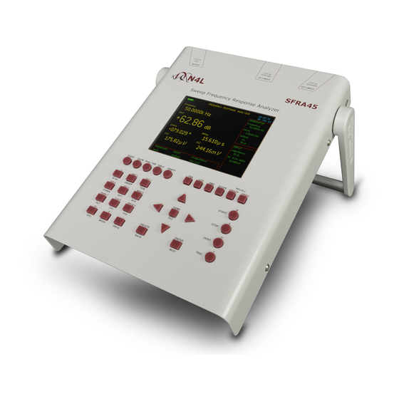
SFRA45
N4L
Sweep Frequency Response Analyzer
RECALL
ZOOM+
ZOOM-
REAL TIME TABLE
GRAPH
FRA
LCR
RMS
SCOPE
SWEEP
PROG
1
ABC 2
DEF 3
START
ACQU
SWEEP
TRIM
GHI 4
JKL 5
MNO 6
HOME
STOP
COMMS
DUT
AUX
ESC
PQRS 7
TUV 8
WXYZ 9
ZERO
OUT
CH1
CH2
+/-
0
.
DELETE
ENTER
TRIG
SYS
MODE
PROG
BACK
NEXT
3.
Connect 2x Earth Braids to Clamp Earth Points
Connect Clamp (A.1) to phase A Transformer Bushing, use braid clamps (B.1) to fasten Earth Braid (C.1) to the local
A PHASE
(A.1)
± 10V pk
Selectable
GEN
CH1
CH2
SFRA CABLE SYSTEM
M
k
m
u
5. EXAMPLE A-B PHASE CONNECTIONS
earthing point. A.2, B.2 and C.2 are connected to phase B respectively
(B.1)
(C.1)
SFRA45 QUICK MEASUREMENT GUIDE
2.
Connect GEN+CH1 BNC Cable Reel Connectors to
First Clamp (Using F-Connector) and CH2 to Second
Clamp
This clamp is referred to as Clamp A.1 in step 5 below
4.
Power on SFRA45, note battery charge level
(B.2)
(C.2)
(A.1)
B PHASE
(A.2)
Advertisement
Table of Contents

Related Manuals for Newtons4th SFRA45


Summary of Contents for Newtons4th SFRA45
- Page 1 PROG BACK NEXT Power on SFRA45, note battery charge level Connect 2x Earth Braids to Clamp Earth Points 5. EXAMPLE A-B PHASE CONNECTIONS Connect Clamp (A.1) to phase A Transformer Bushing, use braid clamps (B.1) to fasten Earth Braid (C.1) to the local earthing point.
- Page 2 Set Output Voltage Level and Generator to Selectable Enter “SWEEP” menu, check sweep settings OUTPUT CH2 INPUT CH1 INPUT “on” SFRA45 Start Frequency Set Output Voltage Stop Frequency No. of Steps Sweep Frequency Response Analyzer Set Output to “ON” After changes are made, continue to press “HOME” until...
- Page 3 SFRA45 SETTING REFERENCE PLOTS Sweep Frequency Response Analyzer Sweep Frequency Response A major benefit of the SFRA45’s standalone proprietary operating system is that the user can compare plots ± 10V pk ± 10V pk ± 10V pk previously recorded. This can be performed in the field, real time without the requirement for a PC connection. It is 50Ω...
- Page 4 TYPICAL TRANSFORMER TEST SEQUENCES AS PER IEC60076-18 Star Connected Winding with Tap Changer CH1 (Clamp A.1, CH2 (Clamp A.2, Test No SIGNAL AND Tap Position RESPONSE) REFERENCE) Line Terminal Phase Neutral Max Turns Line Terminal Phase Neutral Max Turns Line Terminal Phase Neutral Max Turns Line Terminal Phase...
Need help?
Do you have a question about the SFRA45 and is the answer not in the manual?
Questions and answers