Table of Contents
Advertisement
Quick Links
Advertisement
Table of Contents

Subscribe to Our Youtube Channel
Related Manuals for alphatronics AlphaCom PSTN-2-IP ML


Summary of Contents for alphatronics AlphaCom PSTN-2-IP ML
- Page 1 PSTN-2-IP ML Installation Manual...
- Page 2 AL1, AL2 and AL3 norm. The AlphaCom PSTN2IP ML is manufactured with the most modern production methods and complies with RoHS regulations. This means that components used and the soldering procedures are lead-free. Alphatronics b.v. Watergoorweg 71 3861 MA Nijkerk...
-
Page 3: Table Of Contents
TABLE OF CONTENTS INTRODUCTION ................................4 GENERAL ..................................5 SETTINGS ACCORDING TO LOCAL REQUIREMENTS ................... 6 Forcing an alarm message manually ........................6 Dutch regulations AL1, AL2 and AL3 ........................6 QUICK INSTALLATION GUIDE ..........................8 HARDWARE INSTALLATION ..........................10 PSTN tamper loop .............................. -
Page 4: Introduction
INTRODUCTION With the rapid expansion of broadband and Voice over IP connections in homes and businesses, alarm transmissions for burglary systems are often overlooked. In most cases, the regular PSTN modem dialler of the control panel will no longer be able to transmit its messages to the monitoring station. The AlphaCom PSTN2IP ML transceiver is designed as an intelligent interface between control panels and the Internet. -
Page 5: General
The text and illustrations used in this manual are based on the (kernel) firmware version 1.0 of the 19th of December 2007. GENERAL The AlphaCom PSTN2IP ML is an alarm interface used to transmit alarm messages via IP to one or more central stations. -
Page 6: Settings According To Local Requirements
SETTINGS ACCORDING TO LOCAL REQUIREMENTS The AlphaCom PSTN2IP ML can be used in various different applications. In installations were local or European regulations apply (for instance EN50136-1-1 and EN50136-2-1) we strongly advise to take the following into consideration: Access to the web interface must be secured with a username and password. The password chosen must not be a simple and easy password and it is advised to always use a combination of digits and letters. - Page 7 Industry Security Class Regulations for Alarming / transmission Alarm transmission None Alarm transmission according to NEN EN 50136-1- 1 level AL1 Alarm transmission according to NEN EN 50136-1- 1 level AL2 Alarm transmission according to NEN EN 50136-1- 1 level AL2 accompanied with a back-up transmission channel according to level AL1 via a different transmission method (for example GPRS) The above information is based on the „Verbeterde Risicoklassenindeling VRKI 2007‟.
-
Page 8: Quick Installation Guide
QUICK INSTALLATION GUIDE The most common situation in which the AlphaCom PSTN2IP ML transceiver can be placed is a home situation: the residents have an existing alarm installation and decide to switch over to Voice over IP (VoIP) via a cable or ADSL connection. The consequence of this is that the alarm control panel no longer will be able to send its messages to the monitoring station. - Page 9 AlphaCom PSTN2IP ML PROGRAMMING The AlphaCom PSTN2IP ML can now be programmed. Set the laptop‟s IP address to 192.168.0.49 and the subnet mask to 255.255.255.0. The gateway address can be left empty. Now start up your Internet browser and type in the address field 192.168.0.48. The login screen will now appear.
-
Page 10: Hardware Installation
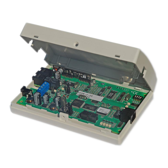
HARDWARE INSTALLATION Backup Telephone line connection Dialler connection RS-485 Bus connection 12VDC jack power adapter Figure 2: AlphaCom PSTN2IP ML circuit board layout The AlphaCom PSTN2IP ML transceiver can be supplied with power in two ways: with the 2,1 mm jack connection (+ in the middle), or directly on the + and 0V terminals of the RS-485 bus connection. -
Page 11: Figure 3: Schematics Pstn Tamper Loop
Figure 3: Schematics PSTN tamper loop Jumper J19 is easy to find using the picture below: J19 is to select the PSTN tamper loop option. Pin 3 of the schematics (0V) is the top pin of the 3. Figure 4: Jumper for PSTN tamper loop To enable the PSTN tamper loop option jumper J19 must be placed over pin 1 and pin 2. - Page 12 The difference with an integrated GSM module (like in the AlphaCom XL GPRS) and an external GSM interface is that the external GSM interface uses a GSM audio connection to transmit the original PSTN protocol via a GSM (audio) connection to the central station. The integrated GPRS (IP over GSM) modules sends data packages over GPRS to the central station and more advanced and more reliable.
-
Page 13: Pstn2Ip Ml Programming
AlphaCom PSTN2IP ML PROGRAMMING The AlphaCom PSTN2IP ML can be programmed through an Internet browser or by means of a DTMF- telephone. See chapter „AlphaCom PSTN2IP ML programming with a DTMF telephone (page. 34) to program the AlphaCom PSTN2IP ML with a DTMF telephone or follow the instructions below to program the AlphaCom PSTN2IP ML with an internet browser. - Page 14 To set-up the fixed IP address, go to Start, Control Panel and open the Dial up and Network connections. The present network connections will now appear on the screen. Right click on the active LAN connection and open the properties menu. The characteristics of this LAN connection will be shown on screen: Service manual AlphaCom PSTN2IP ML transceiver Rev.
- Page 15 Select „Internet-protocol TCP/IP‟ and click „Properties‟. The following screen will appear: Select the option „Use the following IP address‟ and enter 192.168.0.49 at the IP-address field and 255.255.255.0 at the subnet mask field. The default gateway field can be left empty. Press OK to save the changes.
- Page 16 Programming the AlphaCom PSTN2IP ML can be done using a commonly used web browser. Supported versions are Internet Explorer (versions 6 and 7), Mozilla Firefox (version 1.5) and Opera (version 8.5). Attention: Internet Explorer 5.0 (or lower) is not supported! Before programming, the dipswitches on the AlphaCom PSTN2IP ML have to be set to the correct positions.
- Page 17 192.168.0.48:81. The :81 is used to force the browser to use port 81 and only needs to be used when dipswitch 2 is set to OFF. Please note: In Internet Explorer, for „normal‟ web pages, using web port 80, it is not necessary to type in http:// but when using another web port, like 81, it is necessary! Web Port 80 is the standard HTTP port, meaning it can always be reached, regardless of the used router or firewall.
-
Page 18: Log In
This opens a DOS screen, which, among other things, can be used to ping a certain IP address: C:\>ping 192.168.0.48 Pinging 192.168.0.48 with 32 bytes of data: Reply from 192.168.0.48: bytes=32 time=4ms TTL=100 Reply from 192.168.0.48: bytes=32 time=4ms TTL=100 Reply from 192.168.0.48: bytes=32 time=4ms TTL=100 Reply from 192.168.0.48: bytes=32 time=4ms TTL=100 Ping statistics for 192.168.0.48: Packets: Sent = 4, Received = 4, Lost = 0 (0% loss),... - Page 19 As long as dipswitch 2 is set to ON, the AlphaCom PSTN2IP ML does not require a valid password, the password field can be left empty. The supervisor (standard username „admin‟, no standard password) can view and edit all configuration setting and view the status information If a wrong combination of username and password is entered to many times, access to the web interface is blocked and messages are ignored.
- Page 20 After logging is as the supervisor (admin) the status screen is shown on your screen. This is a summary of all statuses of the AlphaCom PSTN2IP ML. By using the menu buttons on the left hand side of the screen you can access certain programming options.
-
Page 21: Ethernet Settings
Configuration Method The PSTN2IP ML is by default configured as DHCP. This means, that the PSTN2IP ML obtains an IP address from a DHCP server. By using the Alphatronics Equipment Discovery tool the obtained IP address can be found easily. -
Page 22: Webserver Configuration
IP address / net mask and standard gateway If the Configuration Method is set to Static, then the programmed fixed IP address will be used. The AlphaCom PSTN2IP ML has a factory default IP address 192.168.0.48 and as subnetmask 255.255.255.0 Talk to your network supervisor to discuss whether a static or dynamic IP address should be used. -
Page 23: Transceiver Settings
Access for supervisor: In this setting it is possible to program a user name and password for the supervisor. The supervisor has the authority to check and change settings of the AlphaCom PSTN2IP ML. To limit remote access to certain external or internal computers it is possible to enter and ip/netmask address. - Page 24 Service manual AlphaCom PSTN2IP ML transceiver Rev. 1.6 10-09-2011 Page 24/65...
- Page 25 For the AlphaCom PSTN2IP ML a total of 4 transceiver channels can be programmed. This is subdivided in 2 transceivers both with their own backup transceiver. By selecting IP transceiver 1, the settings will be displayed for transceiver 1 including the backup transceiver.
-
Page 26: Monitoring Settings / Fault Relay
Monitoring Settings / Fault relay When pressing the button „Input / Output settings‟ in the main menu, the following screen will appear. The first screen that is displayed is the Monitoring Settings. The other options can be chosen by clicking on the buttons on the left-hand side of the screen. - Page 27 The same programming logic of placing an alarm message in the buffer and activating the PSTN prio relay on failure also applies for the power supply failures and other. In the AlphaCom PSTN2IP ML the programming option for power supply failures is not supported. This is only supported in the AlphaCom The settings for tamper switch apply for tamper switch S1 mounted on the AlphaCom PSTN2IP ML board.
-
Page 28: Pstn Interface Settings
In general when connecting non-certified / non-tested products there should be no problems. If you have any questions, please contact the Alphatronics helpdesk. Also an up-to-date list of products tested with the AlphaCom PSTN2IP ML will be listed on the website (www.alphatronics.nl... - Page 29 Selected protocol: Explanation: SIA High Security, only used by Alphatronics SIA-HS products. For dialers using the SIA protocol, such as SIA level SIA (regular) 0, level 1, level 2, level 3 and the Aritech XSIA protocol. Contact ID Ademco Contact ID reporting protocol...
-
Page 30: Serial Port Configuration
A maximum baud rate of 192K applies. For a higher baud rate use two AlphaCom XL modules. The way this application works is stated in a separate document and can be obtained from the Alphatronics helpdesk. - Page 31 Settings Serial port 2 The second serial port is a RS-485 bus. In the default settings this port is „disabled‟. By programming this port to „AlphaVision‟ and connecting it to the RS-485 bus of the AlphaVision control panel the AlphaCom PSTN2IP ML will be seen as a AlphaCom ISDN or AlphaCom IP device on the RS-485 bus with the exception that there is no up/download capabilities.
-
Page 32: Factory Defaults
Factory Defaults When pressing the button „Load factory defaults‟, the following screen will appear. Select the type of settings you want to put back to factory default and then press Load. When selecting all options the AlphaCom PSTN2IP ML will be set back to factory defaults with the exemption of the MAC address. After selecting the appropriate factory defaults and pressing the Load button the factory defaults will be set and the AlphaCom PSTN2IP ML will restart. - Page 33 After logging off or after programming factory defaults the following screen will appear. In this screen the fixed IP address of the AlphaCom PSTN2IP will be displayed. After restarting the AlphaCom PSTN2IP web browser can be reached through this IP address. When using DHCP, it is possible that during a restart the DHCP server will provide the PSTN2IP ML with a new IP address.
-
Page 34: Alphacom Pstn2Ip Ml Programming With A Dtmf-Telephone
AlphaCom PSTN2IP ML PROGRAMMING WITH A DTMF-TELEPHONE The AlphaCom PSTN2IP ML can be programmed using an Internet browser or a DTMF-telephone. The previous chapters explain how to program using an Internet browser. When the AlphaCom PSTN2IP ML is programmed using a DTMF telephone, the router/gateway of the Local Area Network must work with the DHCP protocol to provide the AlphaCom PSTN2IP ML with an IP address. - Page 35 1: SIA-HS / IP 0: No Use Dialer 2 backup 1: Yes PSTN interface configuration 0: Not used 1: SIA-HS (Alphatronics) 2: SIA (regular) Protocol PSTN connection 3: Contact ID 4: Scancom DTMF 1600Hz 5: Scancom DTMF 1400Hz Acknowledgement after IP to control...
- Page 36 Exit the programming by choosing number 99#. The programming is saved. Disconnect the power supply of the AlphaCom PSTN2IP ML, set dipswitch 2 to OFF and apply the power supply again. Connect the analog alarmdialer (of the control panel) to the PSTN input on the AlphaCom PSTN2IP ML. Connect the LAN output to the Local Area Network Apply the power supply to the AlphaCom PSTN2IP ML.
-
Page 37: Operation Of The Pstn2Ip Ml
OPERATION OF THE AlphaCom PSTN2IP ML When the AlphaCom PSTN2IP ML has been programmed, temporarily remove the power supply or short- circuit the reset pins. `When programming by the web server has been completed, make sure to set the dipswitches on the AlphaCom PSTN2IP ML to the correct positions for normal operation: ... -
Page 38: Pstn Back-Up Function
PSTN back-up function The AlphaCom PSTN2IP ML continuously checks the LAN connection and continuously checks if the connection with the monitoring station is established. As soon as either the LAN connection or the connection with the monitoring station is interrupted, the PSTN priority relay will be activated, redirecting the PSTN input (CMK) to the PSTN output (TEL). - Page 39 Description of the TRANSCEIVER LEDs: LED number Colour Description Flashes if the firmware and hardware LED OP2 green functions correctly Illuminates if there is a message in the buffer LED OP3 or if the dialler has not been programmed Status of transceiver 1 and back-up LED OP4 green transceiver 1.
-
Page 40: Dipswitch Settings Of The Pstn2Ip Ml
DIPSWITCH settings of the PSTN2IP ML The functionality of the PSTN-2-IP transceiver is partially determined by the settings of the dipswitches. The meaning of each dipswitch setting is as follows: Dipswitch number Setting Meaning Normal use When dipswitch is ON and the AlphaCom PSTN2IP ML is powered up the factory defaults will be programmed. -
Page 41: New Firmware Flashen In The Alphacom Pstn2Ip Ml (Bios Flash)
Only if you want to use new functionality or you are asked to perform a firmware upgrade by our helpdesk read the following instructions carefully. If you have any doubt please contact the sales department of Alphatronics. Attention: after performing a firmware upgrade we strongly advise to check whether the AlphaCom... - Page 42 Use the ‘Browse’ button to select the new firmware file. Once the correct file has been selected, press ‘Upload’ to send the new firmware file to the AlphaCom PSTN2IP ML. If the write protect jumper J44 is „disabled‟ the above message will be shown on your screen. If the firmware update process is successful, the following screen will appear.
- Page 43 Performing a firmware (bios flash) upgrade locally To flash new firmware, the following items must be present: o Computer or laptop with RS-232 port (or a USB to serial converter) o Serial programming cable (art.nr. 003834). o Flash software FDT (Flash Development Toolkit) o firmware update file Remove the power supply from the AlphaCom PSTN2IP ML.
-
Page 44: Figure 4: Connections For Flash-Mode (Bios-Update)
RS-232 connector for „flash-mode‟ Jumpers J43 and J44 in the „flash-mode‟ Jumper J40 for „flash-mode‟. Watchdog LED. Figure 4: Connections for flash-mode (bios-update) Service manual AlphaCom PSTN2IP ML transceiver Rev. 1.6 10-09-2011 Page 44/65... - Page 45 Start the flash software on your PC. Ensure that the box „User / Data Area‟ has been ticked, and use the find button to select the correct location were the new firmware file has been placed on your PC. In this example it is C:\ALPHACOM XL\BIOS UPDATES\ACOMXL_V1_1.MOT.
- Page 46 The flash software now tries to connect to the processor of the AlphaCom PSTN2IP ML. If this is successful, the message „Connection complete‟ will appear in the message box below: After this the new firmware will be „flashed‟ into the processor of the AlphaCom PSTN2IP ML. In the status bar you can see the percentage of new firmware that has been flashed.
-
Page 47: Figure 5: Jumpers In The „Run-Mode
The firmware has now been correctly upgraded into the AlphaCom PSTN2IP ML. Follow the instructions below to get the AlphaCom PSTN2IP ML up and running again and check if everything works according to specifications. Remove the power supply from the AlphaCom PSTN2IP ML. Remove the serial programming cable between the PC and the AlphaCom PSTN2IP ML Remove jumper J40 Put the jumpers J43 and J44 back to the „run‟... -
Page 48: Appendix A: Installing The Flash Software
APPENDIX A: Installing the FLASH software To be able to „flash‟ new firmware into the AlphaCom PSTN2IP ML a (free) software tool is available from the manufacturer (Renesas) of the microprocessor. Installation of the software is very simple. Install the software by double clicking the fdt_3_06 file (a EXE file). - Page 49 Select the required COM-port were the serial programming cable is connected to. When using a USB to serial converter ensure to select the correct „virtual‟ COM-port that was made. Press Next. Make sure that the AlphaCom PSTN2IP ML is in the correct (flash) mode and then apply the power supply to the AlphaCom PSTN2IP ML.
- Page 50 If something goes wrong with the connection between the PC and the AlphaCom PSTN2IP ML (for example the AlphaCom PSTN2IP ML is not powered up or not connected) press Cancel. If the connection is successful the following screen will be displayed: Press OK.
- Page 51 Select 25.00 MHz as frequency, this is the correct value. Press Next. Press Next. Press the Finish button. The flash tool now tries to connect to the microprocessor in the AlphaCom PSTN2IP ML. If the connection is established, the screen below is displayed with the text Connection complete.
- Page 52 Place a tick in the User / Data Area box. Use the find button (right hand side of the screen) to select the correct firmware file. Service manual AlphaCom PSTN2IP ML transceiver Rev. 1.6 10-09-2011 Page 52/65...
- Page 53 Press the Program Flash button to start the flash procedure. Service manual AlphaCom PSTN2IP ML transceiver Rev. 1.6 10-09-2011 Page 53/65...
- Page 54 When the flash procedure is finished, the text Image successfully written to device will appear in you screen. Press the Disconnect button. Tip: the Disconnect procedure can also been done automatically by selecting the „AutoDisconnect‟ option in the options menu. If the automatic procedure is selected the Disconnect button will not be displayed on the screen Service manual AlphaCom PSTN2IP ML transceiver Rev.
-
Page 55: Appendix B: Dhcp Server Reservations
APPENDIX B: DHCP server reservations Making a reservation on the DHCP server If a DHCP server is present within the network, the AlphaCom PSTN2IP ML can obtain an IP address from the DHCP server. The AlphaCom PSTN2IP ML can also operate with a fixed IP address, this is advisable if the AlphaCom PSTN2IP ML must be reached remotely. - Page 56 In a simpler network, often the ADSL or cable modem is used as a DHCP server. Is this the case, check the IP address range distributed by the modem. When using a fixed IP address for AlphaCom PSTN2IP ML us a fixed IP address outside this range, to avoid conflicts with IP addresses distributed by the modem.
-
Page 57: Appendix C: Cable Wiring
APPENDIX C: Cable wiring To connect the AlphaCom PSTN2IP ML directly to a computer, a cross-over cable has to be used. The wiring of a cross-over cable is as follows: Figure 4: Cross-over cable wiring To connect the AlphaCom PSTN2IP ML to a router, a standard straight through CAT 5 cable is used. A straight through CAT 5 cable is made up as follows: Figure 5: Straight through cable wiring Service manual AlphaCom PSTN2IP ML transceiver... -
Page 58: Appendix D: Reserved Port Numbers
APPENDIX D: Reserved PORT numbers The following PORT numbers are often used. Avoid using them as local port numbers! Port number Port usage ICMP (Internet Control Message Protocol) IGMP (Internet Group Management Protocol) TCP (Transmission Control Protocol) Echo Discard Daytime UDP (User Datagram Protocol) CharGen FTP (File Transfer Protocol) control / printing... -
Page 59: Appendix E: Explanatory Notes
APPENDIX E: Explanatory notes DHCP DHCP stands for Dynamic Host Configuration Protocol. DHCP is a protocol, which describes how a computer can obtain an IP address from a DHCP server. This assignment usually occurs when the DHCP configured machine boots up, or regains connectivity to the network. The DHCP client sends out a query requesting a response from a DHCP server on the locally attached network. - Page 60 In computer networking, the process of network address translation (NAT, also known as network masquerading or IP-masquerading) involves re-writing the source and/or destination addresses of IP Packets as they pass through a router or firewall. Most systems using NAT do so in order to enable multiple hosts on a private network to access the Internet using a single public IP address (see gateway).
- Page 61 the far end sends back an acknowledgement for packets, which have been successfully received; a timer at the sending TCP will cause a timeout if an acknowledgement is not received within a reasonable time, and the (presumably lost) data will then be re-transmitted. The TCP checks that no bytes are damaged by using a checksum;...
-
Page 62: Appendix F: Compatible Control Panels
SIA Level 2 Visonic PowerMax Pro Contact ID ScanCom DTMF 1400 8/16 channels Note: a recent list of tested and supported control panels can be found at the Alphatronics website www.alphatronics.nl/helpdesk. Service manual AlphaCom PSTN2IP ML transceiver Rev. 1.6 10-09-2011 Page 62/65... -
Page 63: Appendix G Sia-Codes
APPENDIX G: SIA-codes For certain functions and programming options it is possible to program a SIA / SIA-HS code. The codes used are usually determined together with the central station. In the table below you will find a list of the most commonly used codes. -
Page 64: Appendix H: Release Notes
APPENDIX H: RELEASE NOTES Installation manual Revision 1.0 15-06-2006 First English manual. Revision 1.1 20-06-2006 Firmware revision 1.8 changes added to the manual. 05-07-2006 English screens added. Revision 1.2 23-11-2006 Table with dipswitch settings added to the manual. Revision 1.3 12-06-2008 Additions added regarding programming with a DTMF telephone Revision 1.4... - Page 65 WEEE-declaration This Alphatronics product is manufactured with the most modern technology and consists of high quality components. Most of the components used can be recycled. The symbol means that this product should be recycled separately and not put in the normal waste bin together with normal household waste.
Need help?
Do you have a question about the AlphaCom PSTN-2-IP ML and is the answer not in the manual?
Questions and answers