Table of Contents
Advertisement
Quick Links
EsiWelma
Istruzioni di installazione
it
Installation instructions
en
Instructiòn de installation
fr
en
English
These instructions must be kept together with the device.
General Information
The
installation,
the
periodical
replacement must be done by qualified technicians.
The installation of a gas leak detection system for methane or
liquid petroleum gas (LPG), do not exempt from the compliance
to the safety rules and to all the laws in force concerning the
installation and the use of gas-operating-devices, for the
ventilation of the rooms and for the discharge of flue gases.
Installation
Mounting
Check that environmental specifications of the installation place are
compatible with the values listed on Technical Data.
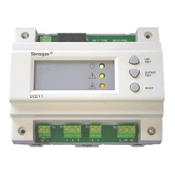
Control Unit UCE11
A
on DIN bar (EN50022-35 x 7.5) min length 120mm
B
on wall, with 2 screws
C on panel front end using a DIN bar length 150mm and
n°2 50mm spacers, screws and washers
A
Sensors UR.13/A
On wall in an area subject to natural air circulation.
Never close to water jets, suction grids, windows, openings, etc.
At a suitable distance from gas devices in order to avoid
unexpected system actions due to functional losses.
In an accessible position for controls and inspections.
s
QAG13/A
EsiWelma
s.r.l.
®
®
s.r.l.
Centralina rivelazione fughe gas
Gas leak detection system
Système de détection de fuite de gaz
inspections,
or
the
B
C
Respect the correct mount orientation
in
order
to
ensure
the
convection air flow inside the sensor.
E202.602_En Rev. 2 dated 30/11/2018
URG13/A:
URG13.P/A:
URO13/A:
NOTE for sensor installation
In case of a new plant the sensor should be installed as latest as
possible so that typical working-place activities (particularly welding,
painting, etc.) cannot damage the sensors (particularly their sensing
element). In any case the installation must be completed before gas
devices and gas appliances are activated.
devices
Wiring
Common electric cables can be used. However, when installing in
places subject to high electromagnetic interference, use of shielded
cables is recommended.
The UCE11 must be permanently powered at 24VAC.
There is no protection against accidental connection with
230V on the 24V side.
Use double insulation safety transformers; they should be sized for
continuous operation at rated power (refer to Technical Data).
Comply with all current regulations for wiring
Connections must be done in accordance with the diagrams
reported in the following operating instructions
Conform to indicated cable length and cross section
Connect only valves at 12VDC with absorbed power not greater
than 13W to EV output
Internal relay with positive logic operation that is always
energized contact in case of alarm or fault absence.
Never touch for any reason the sensing element or
electronic circuit. Any tampering might compromise
the correct system operation.
Commissioning
Control Unit UCE11 does not require any programming or
parameterization.
Check that the sensor is suitable for the gas type to be detected:
URG13/A = Methane sensor
URG13.P/A = LPG sensor
URO13/A = Carbon Monoxide (CO) sensor
Check that power absorbed by any devices connected to relay
terminals is lower than or equal to contacts maximum ratings
(please refer to Technical Data).
If no valve should be connected to EV output, insert a valve
termination Rv 1.8Kohm 1/2W (factory supplied) in the EV
terminal. This will avoid any wrong valve fault signal.
normal
High, 20...30cm from the ceiling, to detect light gases
like methane etc.
Low, 20...30cm from the floor, to detect heavy gases
like LPG, propane, butane etc.
At about 1,5m from the floor, to detect carbon
monoxide (CO)
E202.602_En
Sensigas
®
UCE11
Pag. 1/4
Advertisement
Table of Contents

Related Manuals for EsiWelma Sensigas UCE11


Summary of Contents for EsiWelma Sensigas UCE11
- Page 1 E202.602_En EsiWelma ® s.r.l. Istruzioni di installazione Centralina rivelazione fughe gas Sensigas ® Installation instructions Gas leak detection system UCE11 Instructiòn de installation Système de détection de fuite de gaz English URG13/A: High, 20…30cm from the ceiling, to detect light gases These instructions must be kept together with the device.
- Page 2 During this phase there is voltage at NC solenoid valve, so it is is replaced. possible to open it using its manual actuator placed on the same valve. The relay is energized. Connect the battery to relevant terminals paying attention to polarity. EsiWelma s.r.l. Pag. 2/4 E202.602_En Rev. 2 dated 30/11/2018 ®...
- Page 3 The UCE11 shipping case can be recycled. Retain it for future substances may accelerate normal oxidation process of the sensing use or in case of product return to the manufacturer. element and consequently shorten its decay time (lifetime). EsiWelma s.r.l. ® E202.602_En Rev. 2 dated 30/11/2018...
- Page 4 24VAC power supply terminal 11 12VDC valve terminal Valve Mode Jumper 12 Relay output Due to our policy of continuous product improvement, Dimensions in mm specifications are subject to change without notice. EsiWelma s.r.l. Pag. 4/4 E202.602_En Rev. 2 dated 30/11/2018 ®...
Need help?
Do you have a question about the Sensigas UCE11 and is the answer not in the manual?
Questions and answers