Table of Contents
Advertisement
Quick Links
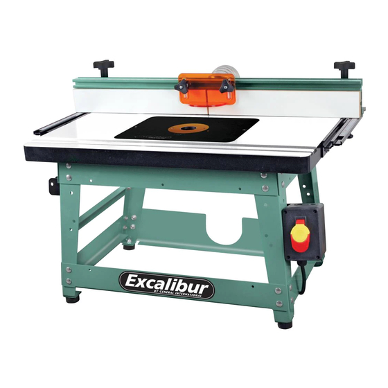
SETUP & OPERATION MANUAL
FEATURES
Heavy-duty massive router lift with 9 1/4" x
11 3/4" aluminum top plate.
Stable 4 post/lift screw design & chain drive
lifting system controlling all 4 corners simul-
taneously.
Fits all fixed base router motors.*
Smooth above-the-table adjustment mech-
anism for fast tool changes & precision bit
setting.
Available with table in either cast-iron (40-
100C), MDF (40-100M) or Phenolic (40-100P).
Sturdy steel stand includes easy access
on/off safety switch with removable lock-
out key & non-slip rubber feet.
Fence has 2 1⁄4" dust collection outlet and
adjustable scales.
Under table steel dust enclosure with
access door, adjustable air vent, power
cord grommet and 4" dust port with 2 1⁄4"
branch inlet to the fence. Includes 2 1⁄4"
dust hose and 2 hose clamps.
*
Some router models may require reducer
collars/adaptors.
SPECIFICATIONS
OVERALL DIMENSIONS
30 1/2" X 16" X 21" (775 X 406 X 533 MM)
TABLE SIZE
Cast-iron: 16" X 27" (406 X 686 MM)
Phenolic & MDF: 15 3/4" X 25 5/8" (400 X 651 MM)
TABLE HEIGHT
16" (406 MM)
FENCE SIZE (EACH)
3" X 15 1/4" X 3/4" (76 X 387 X 19 MM)
MAXIMUM FENCE TRAVEL
6" (152 MM)
DUST OUTLET
2 1/4" (57 MM)
DISTANCE BETWEEN T-SLOT & SPINDLE CENTER
3/4": 5 1/16" (135 MM)
3/8": 6 9/16" (167 MM)
DISTANCE FROM SPINDLE CENTER TO FRONT
EDGE OF TABLE
8" (205 MM)
T-SLOT DIMENSIONS
3/4" X 13/32" (19 X 10 MM) /
3/8" X 9/32" (10 X 7 MM)
ROUTER INSERT PLATE
9 1/4" X 11 3/4 (235 X 298 MM)
TABLE OPENING SIZES - DIAMETER
PLATE: 3 3/4" (95 MM)
INSERT RING: 1 1/2" (38 MM)
NET WEIGHT (40-100C MODEL)
119 LBS (54 KG)
DELUXE ROUTER TABLE KIT
(Bench top model)
MODEL
# 40-100
VERSION 2 _ REVISION 2_DECEMBER 2013
© Copyright General® International
Advertisement
Table of Contents

Related Manuals for General International Excalibur 40-100

Summary of Contents for General International Excalibur 40-100
- Page 1 SETUP & OPERATION MANUAL DELUXE ROUTER TABLE KIT FEATURES (Bench top model) Heavy-duty massive router lift with 9 1/4" x 11 3/4" aluminum top plate. Stable 4 post/lift screw design & chain drive lifting system controlling all 4 corners simul- taneously.
- Page 2 GENERAL® INTERNATIONAL 8360 Champ-d’Eau, Montreal (Quebec) Canada H1P 1Y3 Telephone (514) 326-1161 • Fax (514) 326-5555 • www.general.ca THANK YOU for choosing this Excalibur by General ® International model 40-100 Deluxe Router Table Kit (bench top model). This router table has been carefully tested and inspected before shipment and if properly used and maintained, will provide you with years of reliable service.
- Page 3 GENERAL® INTERNATIONAL WARRANTY All component parts of General® International and Excalibur by General International® prod- ucts are carefully inspected during all stages of production and each unit is thoroughly inspected upon completion of assembly. Limited Lifetime Warranty Because of our commitment to quality and customer satisfaction, General® International agrees to repair or replace any part or component which upon examination, proves to be defective in either workmanship or material to the original purchaser for the life of the tool.
-
Page 4: Table Of Contents
TABLE OF CONTENTS Rules for safe operation ....Operating instructions ....24-26 Installation . -
Page 5: Rules For Safe Operation
Rules for Safe Operation To help ensure safe operation, please take a moment to learn the machine’s applications and limitations, as well as poten- tial hazards. General® International disclaims any real or implied warranty and holds itself harmless for any injury that may result from improper use of its equipment. -
Page 6: Installation
INSTALLATION THE MACHINE IS HEAVY (119 LBS - 54 KG). DO NOT OVEREXERT. ARRANGE TO HAVE HELP NEARBY AND READY FOR UNPACK- ING AND SET UP. SERIOUS PERSONAL INJURY COULD OCCUR IF YOU CONNECT THE MACHINE TO THE POWER SOURCE BEFORE YOU HAVE COM- PLETED THE INSTALLATION AND ASSEMBLY STEPS. -
Page 7: Identification Of Main Parts And Components
DELUXE ROUTER TABLE KIT (Bench top model) Model #40-100 IDENTIFICATION OF MAIN PARTS AND COMPONENTS REAR VIEW ON/OFF SWITCH WITH REMOVABLE SAFETY KEY TABLE* FENCE RAIL WITH SLIDING SCALE SLIDING ADJUSTABLE FENCE FACE FENCE LOCKING HANDLE ROUTER LIFT CRANK HANDLE DUST SHIELD LOCK KNOB DUST SHIELD FENCE BODY... -
Page 8: Unpacking
Carefully unpack and remove the components of the following 5 boxes - that make up a complete Excalibur Router Table - and check for damaged or missing items as per the list of contents below. NOTE: Please report any damaged or missing items to your General International distributor immediately. LIST OF CONTENTS... - Page 9 Carefully unpack and remove the components of the following 5 boxes - that make up a complete Excalibur Router Table - and check for damaged or missing items as per the list of contents below. NOTE: Please report any damaged or missing items to your General International distributor immediately. LIST OF CONTENTS...
-
Page 10: Additional Requirements For Set Up
Carefully unpack and remove the components of the following 5 boxes - that make up a complete Excalibur Router Table - and check for damaged or missing items as per the list of contents below. NOTE: Please report any damaged or missing items to your General International distributor immediately. Model 40-100C:... -
Page 11: Assembly Instructions
ASSEMBLY INSTRUCTIONS SERIOUS PERSONAL INJURY COULD OCCUR IF YOU CONNECT THE MACHINE TO THE POWER SOURCE BEFORE YOU HAVE COMPLE- TED THE INSTALLATION AND ASSEMBLY STEPS. DO NOT CONNECT THE MACHINE TO THE POWER SOURCE UNTIL INSTRUCTED TO DO 40-060 ROUTER TABLE STAND Note: Do not tighten the stand bolts until after you have fastened the stand to the router table top. - Page 12 7. Attach the two bottom side cross braces, P and Q. 9. Using a carriage bolt, flat washer and nut, S, attach the router lift crank handle holder T to the 8. Turn the stand in the upright position and attach middle cross brace as shown in U.
-
Page 13: Cleaning The Cast-Iron Table (For #40-100 Only)
TABLE 40-070/40-047/40-043 There are 3 different table options for Deluxe Router Table Kit, model 40-100: Phenolic table (#40-043) for 40-100P Cast-iron table (#40-070) for 40-100C MDF table (#40-047) for 40-100M CLEANING THE CAST-IRON TABLE FOR #40-100C ONLY) The protective coating on the cast-iron table, prevents rust from forming during shipping and storage. -
Page 14: Attach The Table To The Stand
ATTACH THE TABLE TO THE STAND (CAST-IRON TABLE #40-100C AND PHENOLIC TABLE #40-100P ONLY)* * For #40-047 MDF table (for #40-100M), use the wood screws supplied with your table to attach the stand to the table. 2. Attach the stand to the table using the four socket 1. - Page 15 3. Attach the second mounting bracket to the oppo- 4. Insert an orange plastic spacer A with the short end site side of the table, A. down on one short T- bolt B, then insert the head of the bolt in the front upper slot in the fence body as Note: Adjust the height of the 3 bolts in the slotted holes in the rail bracket so that the rail is leveled with the table, shown in C.
- Page 16 9. Slide the slot of one fence face onto the 3 elongat- 10. Repeat with the second fence face on the other ed bolt heads, then tighten the lock knobs on the side of the fence body. other side of the fence. 11.
-
Page 17: Prepare The Table For Router Lift
PREPARE THE TABLE FOR THE ROUTER LIFT Note: Model #40-070 for 40-100C Cast-iron table shown. The following steps apply to all 3 table options. 1. Place the router lift into the opening in the table. 2. Use a straightedge to test the plate for level with the table top. -
Page 18: 40-130 Dust Collection Kit
40-130 DUST COLLECTION KIT Note: There are three longer screws in the hardware kit that are required to attach the 4 inch hose adapter. Locate them first. You will find additional mounting hardware to attach the 40-130 dust enclosure to the table. This additional hardware will not be required with cast-iron table for 40-100C because the same fasteners are supplied with the table. -
Page 19: Mounting A Router
ASSEMBLY INSTRUCTIONS - MOUNTING A ROUTER SERIOUS PERSONAL INJURY COULD OCCUR IF YOU CONNECT THE MACHINE TO THE POWER SOURCE BEFORE YOU HAVE COM- PLETED THE INSTALLATION AND ASSEMBLY STEPS. DO NOT CONNECT THE MACHINE TO THE POWER SOURCE UNTIL INSTRUCTED TO DO SO. - Page 20 Turn Allan cap screw A counter clockwise to Note: When mounting the Milwaukee model 5625/5626 motor, please ensure that a shim is between the router loosen clamp body B. The two threaded nuts C and the clamping surface of the lift. are there to help spread the clamp body.
-
Page 21: Leveling And Locking The Router Plate
LEVELING AND LOCKING THE ROUTER PLATE 4. The routers collet should now be protruding out from 1. Using a straightedge check that the router plate is the top plate. This will facilitate tool (router bit) level with the main table, A. changing from above the table eliminating the 2. -
Page 22: Basic Adjustments & Controls
BASIC ADJUSTMENTS & CONTROLS ADJUSTING THE FENCE ALONG THE RAILS ADJUSTING THE SLIDING SCALE ON THE RAILS The fence can be slid along the rails A. Loosen locking The scale on the rails can be adjusted along the rails handles B, slide fence then lock in position by re-tight- C. -
Page 23: Using The Safety Switch
USING THE SAFETY SWITCH POWER ON POWER OFF SAFETY KEY (PREVENTS START-UP WHEN REMOVED) The safety switch box is equipped with a simple “on/ With the safety switch on the stand in the “off” position off” switch featuring a removable lock out safety key. A, turn or flip the switch on your router to the “on”... -
Page 24: Using The Spacer Bars For Jointing
USING THE SPACER BARS FOR JOINTING Jointing the edge of a board involves using a straight Two spacer bars A are supplied with the fence system cutting router bit to remove material from the edge to facilitate jointing, by offsetting the outfeed fence B face of a board. -
Page 25: Groove Cutting
GROOVE CUTTING Beading is commonly defined as cutting a groove or bead in the face of a board. 1. If installed, remove the spacer bars on the outfeed fence. 2. With the router unplugged and the safety switch in the off position, follow the instructions supplied with your router and install a cutting bit in the router. - Page 26 RECOMMENDED OPTIONAL ACCESSORIES We offer some optional accessories available from your local General International dealer for increased con- venience, productivity, accuracy and safety when using your router table. For more information about our products, please visit our website at www.general.ca...
- Page 27 Cast-iron table (with models #40-100C & #40-070EK ) PARTS LIST – #40-070 PART NO. REFERENCE NO. DESCRIPTION SPECIFICATION 40070-01 2716U014 CAST-IRON TABLE 16” X 27” 40075-02 903M06030 FLAT HEAD CAP SCREW M6 X 30 MM 40075-03 910M06000 HEX NUT 40075-04 905M06020 FLAT HEAD SCREW M6 X 20 MM...
- Page 28 MDF table (with model #40-100M) PARTS LIST – #40-047 PART NO. REFERENCE NO. DESCRIPTION SPECIFICATION 40047-01 2716E014B MDF TABLE 400 X 600 MM 40049-02 903M06030 FLAT HEX SOCKET HEAD SCREW M6 X 30 40049-03 907M06013 WOOD NUT M6 X 13 40049-04 907007004 WOOD SCREW...
- Page 29 Router Fence (#40-065) 6 17 PARTS LIST – #40-065 PART NO. REF. N0. DESCRIPTION SPECIFICATIONS 4006501 27160032A FENCE BODY 780 MM 40080-02 60100001A LOCK HANDLE 5/16” 40065-03 T2716002 SCALE 780 MM 40080-04 32240052A T-BOLT 40080-05 9145162302 FLAT WASHER 40080-06 939M08000B LOCK KNOB 40080-07 32240034...
- Page 30 Stand (#40-060) PARTS LIST – #40-060 PART NO. REF. NO. DESCRIPTION SPECIFICATIONS 40060-02 27160015 LONG TOP BRACE (F&R) 40060-03 27160016 SHORT TOP CROSS BRACE (L&R) 40060-04 27160017 40060-05 27160018 LONG BOTTOM CROSS BRACE (FRONT) 40060-06 27160018A LONG BOTTOM CROSS BRACE (REAR) 40060-07 27160019 SHORT BOTTOM CROSS BRACE (L&R)
- Page 31 Router lift (#40-125)
- Page 32 PARTS LIST – #40-125 PART NO. REF. N0. DESCRIPTION SPECIFICATIONS 0125-01 60800001A ALUMINUM CARRIAGE BRACKET 40125-02 60500002 MAIN GEAR SHAFT 40125-03 60500003 LEAD SCREW 40125-04 60100017 INSERT RING 1-1/2” 40125-05 60500005 GEAR SHAFT 40125-06 60800021 CARRIAGE PLATE 40125-07 60800004 CLAMP POST 40125-08 60800007A TOP PLATE...
- Page 33 Dust Collection Kit (#40-130) PARTS LIST – #40-130 PART NO. REF. NO. DESCRIPTION SPECIFICATIONS 40130-01 32240001 FRONT BOX PANEL 40130-02 32240002 RIGHT BOX PANEL 40130-03 906M04006A PHILLIPS HEAD SCREW 40130-04 906M04010A PHILLIPS HEAD SCREW 40130-05 32240003 HINGE 40130-06 32240004 LEFT BOX PANEL 40130-07 32240005 REAR BOX PANEL...
- Page 34 MODEL 40-100 8360 Champ-d’Eau, Montreal (Quebec) Canada H1P 1Y3 Tel.: (514) 326-1161 Fax: (514) 326-5565 - Fax: (514) 326-5555 - Parts & Service / Order Desk orderdesk@general.ca www.general.ca IMPORTANT When ordering replacement parts, always give the model number, serial number of the machine and part number.
Need help?
Do you have a question about the Excalibur 40-100 and is the answer not in the manual?
Questions and answers