3Com SuperStack 3 3812 Getting Started Manual
3com superstack 3 3812: quick start
Hide thumbs
Also See for SuperStack 3 3812:
- Implementation manual (110 pages) ,
- Getting started manual (72 pages) ,
- Datasheet (4 pages)

Subscribe to Our Youtube Channel
Related Manuals for 3Com SuperStack 3 3812


Summary of Contents for 3Com SuperStack 3 3812
-
Page 1: Switch 3812 And Switch 3824
Switch 3812 and Switch 3824 Getting Started Guide 3C17401 3C17400 http://www.3com.com/ Part No. DUA1740-0AAA01 Published May 2003... - Page 2 3Com Corporation reserves the right to revise this documentation and to make changes in content from time California 95052-8145 to time without obligation on the part of 3Com Corporation to provide notification of such revision or change. 3Com Corporation provides this documentation without warranty, term, or condition of any kind, either implied or expressed, including, but not limited to, the implied warranties, terms or conditions of merchantability, satisfactory quality, and fitness for a particular purpose.
-
Page 3: Table Of Contents
ONTENTS BOUT UIDE Before You Start About Your CD-ROM Conventions Related Documentation Accessing Online Documentation Documentation Comments Product Registration NTRODUCING THE About the Switch Summary of Hardware Features Switch — Front View Detail 10BASE-T/ 100BASE-TX/ 1000BASE-T Ports SFP Ports LEDs Console Port Switch —... - Page 4 IP Configuration Preparing for Management Manually Configuring IP Information Connecting to the Console Port Viewing Automatically Configured IP Information Using 3Com Network Supervisor Connecting to the Console Port Methods of Managing a Switch Command Line Interface Management Web Interface Management...
- Page 5 ECHNICAL PECIFICATIONS Switch 3812 and Switch 3824 ECHNICAL UPPORT Online Technical Services World Wide Web Site 3Com Knowledgebase Web Services 3Com FTP Site Support from Your Network Supplier Support from 3Com Internet Support Telephone Support Returning Products for Repair Contacting 3Com Support...
-
Page 7: About This Guide
3C17401 — 3Com Switch 3812 (12-port, Managed Gigabit) 3C17400 — 3Com Switch 3824 (24-port, Managed Gigabit) Online documentation for the Switch — refer to Documentation page 9 for details. 3Com Network Supervisor — a powerful and easy-to-use network management platform. UIDE Related... -
Page 8: Conventions
BOUT UIDE Most user guides and release notes are available in Adobe Acrobat Reader Portable Document Format (PDF) or HTML on the 3Com World Wide Web site: http://www.3com.com/ Conventions Table 1 Table 1 Notice Icons Table 2 Text Conventions Convention... -
Page 9: Related Documentation
HTML format on the CD-ROM that accompanies the Switch. Release Notes These notes provide information about the current software release, including new features, modifications, and known problems. Documentation accompanying 3Com Network Supervisor. This is supplied on the CD-ROM that accompanies the Switch. Related Documentation... -
Page 10: Accessing Online Documentation
CD-ROM contents via the root directory and copy the files from the CD-ROM to a suitable directory. 3Com recommends that you copy the Docs/reference directory as a whole to maintain the structure of the files. -
Page 11: Product Registration
Product You can now register your Switch on the 3Com Web site: Registration http://www.3com.com/register/ You will need your product part number (3Cxxxxx), product serial number and date and place of purchase to register your 3Com product. - Page 12 BOUT UIDE...
- Page 13 NTRODUCING THE This chapter contains introductory information about the Switch 3812 and Switch 3824 and how they can be used in your network. It covers summaries of hardware and software features and also the following topics: About the Switch Switch — Front View Detail Switch —...
-
Page 14: About The Switch
1: I HAPTER NTRODUCING THE About the Switch The Switch is a 10/100/1000 Mbps Ethernet Switch, which consists of 4 SFP ports and either: The last four 10/100/1000 ports are combination ports. When an SFP port is active it has priority over the 10/100/1000 port of the same number (9 -12 on the 12-port Switch, 21-24 on the 24-port Switch). -
Page 15: Switch - Front View Detail
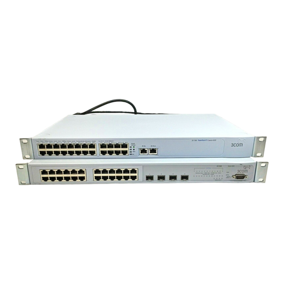
Switch — Front Figure 1 Switch 3812— front view View Detail 10BASE-T / 100BASE-TX / 1000BASE-T Ports Figure 2 Switch 3824— front view 10BASE-T / 100BASE-TX / 1000BASE-T Ports WARNING: RJ-45 Ports. These are shielded RJ-45 data sockets. They cannot be used as standard traditional telephone sockets, or to connect the unit to a traditional PBX or public telephone network. -
Page 16: Sfp Ports
1: I HAPTER NTRODUCING THE The default state for 10/100/1000 Mbps ports is auto-negotiation enabled, where the speed, duplex and flow control modes are negotiated. Alternatively, auto-negotiation can be disabled and the speed, duplex and flow control setting can be manually configured. The last four 10/100/1000 ports are combination ports. -
Page 17: Console Port
Module Active LEDs Self Test LED Power LED Console Port The console port allows you to connect a terminal and perform remote or local out-of-band management. The console port uses a standard null modem cable and is set to auto-baud, 8 data bits, no parity and 1 stop bit. -
Page 18: Default Settings
1: I HAPTER NTRODUCING THE Default Settings Table 5 Table 5 Default Settings If you initialize a Switch unit by selecting System > Control > Initialize in the Web interface or by entering system control initialize in the Command Line Interface, the following settings are retained to allow you to connect to and manage the Switch: 3812 3824... -
Page 19: Installing The Switch
NSTALLING THE This chapter contains the information you need to install and set up the Switch. It covers the following topics: Package Contents Choosing a Suitable Site Rack-mounting Placing Units On Top of Each Other The Power-up Sequence WARNING: Safety Information. Before installing or removing any components from the Switch or carrying out any maintenance procedures, you must read the safety information provided in of this guide. -
Page 20: Package Contents
Water or moisture cannot enter the case of the Switch. Air flow is not restricted around the Switch or through the vents in the side of the Switch. 3Com recommends that you provide a minimum of 25mm (1in.) clearance. Air temperature around the Switch does not exceed 40 (104 °C... -
Page 21: Rack-Mounting
Rack-mounting The Switch is 1U high and will fit in most standard 19-inch racks. CAUTION: Disconnect all cables from the Switch before continuing. Remove all self adhesive pads from the underside of the Switch if they have been fitted. To rack-mount your Switch: 1 Place the Switch the right way up on a hard flat surface, with the front facing towards you. - Page 22 (not provided). Ensure that ventilation holes are not obstructed. position. The unit information label shows the following: The 3Com product name of the Switch The 3Com 3C number of the Switch The unique MAC address (Ethernet address) of the Switch The serial number of the Switch You may need this information for fault reporting purposes.
-
Page 23: Placing Units On Top Of Each Other
If the Switch units are free-standing, up to eight units can be placed one Top of Each Other on top of the other. If you are mixing a variety of 3Com Switch and Hub units, the smaller units must be positioned at the top. -
Page 24: Choosing The Correct Cables
MDI port, you need to use a standard straight-through cable. See 3Com recommends that you use Category 5 twisted pair cable — the maximum segment length for this type of cable is 100 m (328 ft). WITCH... -
Page 25: Sfp Operation
Table 8 Cables required to connect the Switch to other devices if CAUTION: If you want to install the Switch using a Category 5E or Category 6 cable, 3Com recommends that you briefly connect the cable to a grounded port before connecting network equipment. If you do not, the cable’s Electrostatic Discharge (ESD) may damage the Switch’s port. -
Page 26: Inserting An Sfp Transceiver
If the SFP transceiver is faulty, it will not operate within the Switch. See “Solving Hardware Use of non-3Com SFPs is not recommended. If the SFP transceiver is invalid it will not be recognised by the Switch. Use the following sequence of steps to activate the SFP ports:... -
Page 27: Removing An Sfp Transceiver
Figure 5 Inserting a SFP Transceiver 5 The transceiver connects to the network using a duplex SC connector. Attach a male duplex SC connector on the network cable into the duplex SC connector on the transceiver. 6 Connect the other end of the cable to a device fitted with an appropriate Gigabit Ethernet connection. - Page 28 2: I HAPTER NSTALLING THE WITCH...
-
Page 29: Setting U P For Management
ETTING Your Switch can operate in its default state, that is, you can install it and it will work straight away (plug-and-play). However, to make full use of the features offered by the Switch, and to change and monitor the way it works, you have to access the management software that resides on the Switch. -
Page 30: Setting Up Overview
6. Detailed procedural steps Power Up the Switch. page 31 Do you want to manually How do you want to view the automatically configured IP information? Use 3Com Network Connect to the console Supervisor (3NS). page 36 SNMP Web Interface Connect over the network. -
Page 31: Automatic Ip Configuration
(Static IP addresses are necessary to ensure that the Switch is always allocated the same IP information.) For most installations, 3Com recommends that you configure the Switch IP information manually. This makes management simpler and more reliable as it is not dependent on a DHCP server, and eliminates the risk of the IP address changing. -
Page 32: Preparing For Management
“Switch Management Interface Reference Guide” on the CD-ROM that is supplied with the Switch or on the 3Com Web site. ANAGEMENT your network uses DHCP to allocate IP information, or flexibility is needed. -
Page 33: Manually Configuring Ip Information
Manually You can manually configure the Switch IP information in the following Configuring IP way: Information Connecting to the To set up your Switch manually you can make a connection to the console Console Port port (this example describes a local connection to the console port, rather than a remote one via a modem). - Page 34 3: S HAPTER ETTING P FOR Connecting the Workstation to the Switch 1 Connect the workstation to the console port using a standard null modem cable as shown in Figure 7 Connecting a workstation to the Switch via the console port To connect the cable: a Attach the female connector on the cable to the male connector on b Tighten the retaining screws on the cable to prevent it from being...
- Page 35 2 At the login and password prompts, enter admin as your user name and press Return at the password prompt. If you have logged on correctly, the top-level menu of the command line interface is displayed as shown in the example in Figure Figure 8 Example top-level command line interface menu 3 At the Select menu option prompt you can either:...
-
Page 36: Viewing Automatically Configured Ip Information
Switch. You can discover the IP information in two ways: Information Using 3Com Network You can use the 3Com Network Supervisor application provided on the Supervisor CD-ROM that accompanies your Switch to discover the automatically allocated IP information. - Page 37 Viewing Automatically Configured IP Information You can find pin-out diagrams for the cable in A Category 5 twisted pair Ethernet cable with RJ-45 connectors to connect your Switch to the network. Connecting the Workstation to the Switch 1 Connect the workstation to the console port using a standard null modem cable as shown in Figure 9 Connecting a workstation to the Switch via the console port Workstation...
- Page 38 3: S HAPTER ETTING P FOR Viewing IP Information via the Console Port You are now ready to view the automatically allocated IP information using the command line interface. 1 Connect your Switch to the network using an Ethernet cable. As soon as a network connection is made the Switch begins the automatic IP configuration process.
-
Page 39: Methods Of Managing A Switch
Methods of Once you have completed the initial set up of your Switch, you can Managing a Switch decide how you wish to manage the Switch. You can use one of the following methods: Command Line Each Switch has a limited command line interface (CLI) that allows you to Interface manage the Switch from a workstation, either locally via a console port Management... -
Page 40: Snmp Management
2 Your Switch is now ready to continue being managed and/or configured through the CLI via its console port. ANAGEMENT “Setting Up Web Interface Management” 14. For example, you can use the 3Com Network Supervisor “Setting Up SNMP Management” “Connecting to the Console Port” page... -
Page 41: Cli Management Over The Network
CLI Management over To manage a Switch using the command line interface over a network the Network using Telnet: 1 Ensure you have already set up the Switch with IP information as described in 2 Check that you have the IP protocol correctly installed on your management workstation. -
Page 42: Setting Up Web Interface Management
3: S HAPTER ETTING P FOR Setting Up Web This section describes how you can set up web interface management Interface over the network. Management Pre-requisites Choosing a Browser To display the web interface correctly, use one of the following Web browser and platform combinations: Table 9 Supported Web Browsers and Platforms Netscape 7... -
Page 43: Setting Up Snmp Management
Management Management Protocol (SNMP) can manage a Switch if: You can use the 3Com Network Supervisor application that is provided on the CD-ROM that accompanies your Switch to provide SNMP management for your Switch. If you use 3Com Network Supervisor it automatically loads the correct MIBs and necessary files onto your workstation. -
Page 44: Changing Default Passwords
3: S HAPTER ETTING P FOR CAUTION: To protect your Switch from unauthorized access, you must change the two default passwords as soon as possible, even if you do not intend to actively manage your Switch Table 10 Default Users User Name monitor... -
Page 45: Problem Solving
ROBLEM This chapter helps you to diagnose and solve problems you may have with the operation of your Switch. There is also an explanation of IP addressing. The topics covered are: Solving Problems Indicated by LEDs Solving Hardware Problems Solving Communication Problems Solving Software Upgrade Problems If you experience a problem that is not listed here, it may be included in the Support section of the Switch Management Interface Reference... -
Page 46: Solving Problems Indicated By Leds
4: P HAPTER ROBLEM OLVING Solving Problems If the LEDs on the Switch indicate a problem, refer to the list of suggested Indicated by LEDs solutions below. The Power LED does not light Check that the power cable is firmly connected to the Switch and to the supply outlet. -
Page 47: Solving Hardware Problems
A link is connected and yet the Status LED for the port does not light Check that: Solving Hardware In the rare event of your Switch unit experiencing a hardware failure, Problems refer to the list of suggested solutions below. A fan failure warning message is received Your Switch has a fan monitoring system that will generate fan failure warning messages. -
Page 48: Solving Communication Problems
IP address of the router. The Switch’s IP address has been entered correctly in your network management application (such as 3Com Network Supervisor). The first part (‘192.168.100’ in the example) identifies the network on which the device resides The second part (‘.8’... -
Page 49: Solving Software Upgrade Problems
If your IP network is internal to your organization only, that is, you do not access the Internet, you may use any arbitrary IP address as long as it is not being used by another device on your network. 3Com suggests you use addresses in the range 192.168.0.0 to 192.168.255.255 with a subnet mask of 255.255.255.0. - Page 50 4: P HAPTER ROBLEM OLVING...
-
Page 51: A Safety Information
You must read the following safety information before carrying out any installation or removal of components, or any maintenance procedures on the Switch. WARNING: Warnings contain directions that you must follow for your personal safety. Follow all directions carefully. You must read the following safety information carefully before you install or remove the unit. -
Page 52: Important Safety Information
A: S PPENDIX AFETY NFORMATION Important Safety Information WARNING: Installation and removal of the unit must be carried out by qualified personnel only. WARNING: The unit must be earthed (grounded). WARNING: Connect the unit to an earthed power supply to ensure compliance with safety standards. -
Page 53: L'information De Sécurité Importante
L’information de Sécurité Importante WARNING: This unit operates under SELV (Safety Extra Low Voltage) conditions according to IEC60950. The conditions are only maintained if the equipment to which it is connected also operates under SELV conditions. WARNING: France and Peru only: †... - Page 54 A: S PPENDIX AFETY NFORMATION AVERTISSEMENT: Cordon électrique: Il doit être agréé ans le pays d'utilisation: AVERTISSEMENT: Le coupleur d'appareil (le connecteur du groupe et non pas la prise murale) doit respecter une configuration qui permet un branchement sur une entrée d'appareil EN60320/CEI 320. AVERTISSEMENT: La prise secteur doit se trouver à...
-
Page 55: Wichtige Sicherheitsinformationen
connexion portant l'appellation Neutre et avec raccordement direct à la terre (masse). AVERTISSEMENT: Points d’accès RJ-45. Ceux-ci sont protégés par des prises de données. Ils ne peuvent pas être utilisés comme prises de téléphone conventionnelles standard, ni pour la connection de l’unité à un réseau téléphonique central privé... - Page 56 A: S PPENDIX AFETY NFORMATION Der Netzstecker muß die Norm CEE 7/7 erfüllen (”SCHUKO”). VORSICHT: Der Betrieb dieses Geräts erfolgt unter den SELV-Bedingungen (Sicherheitskleinstspannung) gemäß IEC60950. Diese Bedingungen sind nur gegeben, wenn auch die an das Gerät angeschlossenen Geräte unter SELV-Bedingungen betrieben werden. VORSICHT: RJ-45-Porte.
-
Page 57: In Outs
Null Modem Cable 9-pin to RS-232 25-pin Switch 3812 and Switch 3824 Cable connector: 9-pin female PC-AT Serial Cable 9-pin to 9-pin Switch 3812 and Switch 3824 Cable connector: 9-pin female OUTS Screen Shell Ground Screen Shell Ground PC/Terminal Cable connector: 25-pin male/female Screen only required if screen always required... -
Page 58: Modem Cable
B: P PPENDIX OUTS Modem Cable 9-pin to RS-232 25-pin Switch 3812 and Switch 3824 Cable connector: 9-pin female RJ-45 Pin Pin assignments are identical for 10BASE-T and 100BASE-TX RJ-45 Assignments connectors. Table 11 Pin assignments Screen Shell Ground Pin Number 10/BASE-T/100BASE-TX Ports configured as MDI Transmit Data +... - Page 59 Table 12 Pin assignments Pin Number 10BASE-T/100BASE-TX Ports configured as MDIX Receive Data + Receive Data - Transmit Data + Not assigned Not assigned Transmit Data Not assigned Not assigned RJ-45 Pin Assignments 1000BASE-T Bidirectional Data B+ Bidirectional Data B- Bidirectional Data A+ Bidirectional Data A- Bidirectional Data D+...
- Page 60 B: P PPENDIX OUTS...
-
Page 61: Specifications
–40 ° to +70 °C (-40 ° to 158 °F) 10–95% relative humidity, non-condensing EN60068 to 3Com schedule (Package testing: paras 2.1, 2.2, 2.30, and 2.32. Operational testing: paras 2.1, 2.2, 2.30 and 2.13). UL60950, EN60950, CSA 22.2 No. 60950, IEC 60950... - Page 62 C: T PPENDIX ECHNICAL PECIFICATIONS Standards Supported SNMP SNMP protocol (RFC 1157) MIB-II (RFC 1213) Bridge MIB (RFC 1493) RMON MIB II (RFC 2021) Remote Monitoring MIB (RFC 1757) MAU MIB (RFC 2239) Terminal Emulation Telnet (RFC 854) Protocols Used for Administration UDP (RFC 768) IP (RFC 791) ICMP (RFC 792)
-
Page 63: D Technical Support
3Com recommends that you access the 3Com Corporation World Wide Web site. Online Technical 3Com offers worldwide product support 24 hours a day, 7 days a week, Services through the following online systems: World Wide Web Site... -
Page 64: 3Com Knowledgebase Web Services
Knowledgebase is updated daily with technical information discovered by 3Com technical support engineers. This complimentary service, which is available 24 hours a day, 7 days a week to 3Com customers and partners, is located on the 3Com Corporation World Wide Web site at: http://knowledgebase.3com.com... -
Page 65: Support From 3Com
Support from 3Com If you are unable to obtain assistance from the 3Com online technical resources discussed earlier in this appendix, or from your network supplier, 3Com offers a range of support services. Purchase of a support contract gives you priority response and is typically more cost effective than purchasing service for a specific incident. - Page 66 D: T PPENDIX ECHNICAL UPPORT Here is a list of worldwide technical telephone support numbers. These numbers are correct at the time of publication. Refer to the 3Com Web site for updated information. Country Telephone Number Asia, Pacific Rim Australia...
-
Page 67: Returning Products For Repair
Returning Products Before you send a product directly to 3Com for repair, you must first for Repair obtain an authorization number. Products sent to 3Com without authorization numbers will be returned to the sender unopened, at the sender’s expense. You can obtain a Return Materials Authorization number (RMA) by entering the following URL into your Internet browser: http://www.3com.com/support/en_US/repair... -
Page 68: Contacting 3Com Support
If you do not wish to be contacted, please inform our support representative. Calls may be recorded for training purposes. Any data collected during the call will be stored by 3Com at a secure location in the United States. For details of 3Com's Privacy Statement, please refer to: http://www.3com.com... -
Page 69: Index
NDEX Numbers 3C number 22 3Com Knowledgebase Web Services 64 3Com URL 63 access levels of default users 43 automatic setup 36 3Com Network Supervisor 36 console port 36 browsers choosing 42 cable choosing the correct 24 pin-outs 57 CD-ROM 10... - Page 70 21 serial number 22 size 61 unit information label 22 weight 61 system specifications 61 technical support 3Com Knowledgebase Web Services 64 3Com URL 63 network suppliers 64 product repair 67 troubleshooting 45 unit information label 22 URL 63...
- Page 71 Warning: This is a class A product. In a domestic environment this product may cause radio interference in which case the user may be required to take adequate measures. You must only insert a 3Com approved SFP transceiver into the Switch. These are listed in the "Approved SFP Transceivers" section of the Getting Started Guide.
Need help?
Do you have a question about the SuperStack 3 3812 and is the answer not in the manual?
Questions and answers